1989 MITSUBISHI GALANT wheel alignment
[x] Cancel search: wheel alignmentPage 926 of 1273
FRONT SUSPENSION - Service Adiustment Procedures33A-5
eI
-a,
-
\ ~,I 1, 1
FY
TSB Revision
SERVICE ADJUSTMENT PROCEDURES
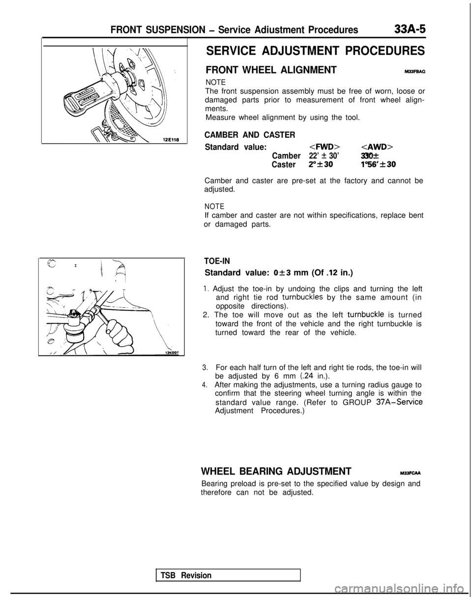
FRONT WHEEL ALIGNMENTM33FBAQ
NOTE
The front suspension assembly must be free of worn, loose or
damaged parts prior to measurement of front wheel align- ments. Measure wheel alignment by using the tool.
CAMBER AND CASTER
Standard value:
Camber22’ f 30’ 31’& 30
Caster2”f301”56’rtr30
Camber and caster are pre-set at the factory and cannot be
adjusted.
NOTE
If camber and caster are not within specifications, replace bent
or damaged parts.
TOE-IN
Standard value: Ok3 mm (Of .12 in.)
1. Adjust the toe-in by undoing the clips and turning the left and right tie rod turnbuckles
by the same amount (in
opposite directions).
2. The toe will move out as the left turnbuckle
is turned
toward the front of the vehicle and the right turnbuckle is
turned toward the rear of the vehicle.
3.For each half turn of the left and right tie rods, the toe-in will
be adjusted by 6 mm
(24 in.).
4.After making the adjustments, use a turning radius gauge to confirm that the steering wheel turning angle is within the
standard value range. (Refer to GROUP
37A-Service
Adjustment Procedures.)
WHEEL BEARING ADJUSTMENTM?SCAA
Bearing preload is pre-set to the specified value by design and
therefore can not be adjusted.
Page 928 of 1273
FRONT SUSPENSION - Strut Assembly33A-7
/Strut
insulator
Front 12A0003SERVICE POINTS OF INSTALLATIONM33lDAG
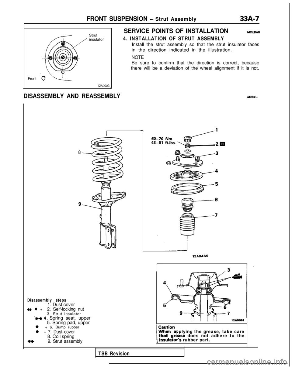
4. INSTALLATION OF STRUT ASSEMBLY
Install the strut assembly so that the strut insulator faces
in the direction indicated in the illustration.
NOTE
Be sure to confirm that the direction is correct, because
there will be a deviation of the wheel alignment if it is not.
J
DISASSEMBLY AND REASSEMBLY
8
Disassembly steps1. Dust cover+I) l +2. Self-locking nut3. Strut insulator‘+* 4. Spring seat, upper
5. Spring pad, upper
l + 6. Bump rubber
l + 7. Dust cover8. Coil spring
+*9. Strut assembly
60-70 Nm
12A0469
: :: II12AOO61
When applying the grease, take care
1 ~~~~~~r s rubber part.\that gre?se does not adhere to the
TSB Revision
Page 940 of 1273
339-l
ACTIVE-ELECTRONIC
CONTROL
SUSPENSION
ACTIVE-ECS RELAY......................................141
ACTIVE-ECSSENSOR.................................. 138
AIRCOMPRESSOR.......................................125
AIR TUBE.......................................................133
CONTROLUNIT............................................ 140
HEIGHT SENSOR ..........................................
135
INDICATORASSEMBLY............................... 140
LATERALROD...............................................117
LOWER
ARM.................................................103
REAR
SUSPENSION ASSEMBLY................114
RESERVETANK............................................ 122
SERVICE ADJUSTMENT PROCEDURES.....86
Alarm Light Check.....................................87
Checking by On-board Diagnostic ..............88
FrontWheelAlignment .............................. 86
G sensor Output Voltage Check ...............96
High-pressure Switch
(High-pressure Tank Side)
Actuation Pressure Check
.......................... 94
Hub End Play Inspection ...........................86 M33AA-
Low-pressure Switch
(Low-pressure Tank Side)
Actuation
PressureCheck . . . . . . . . . . . . . . . . . . . . . . . . .95
Normal Vehicle Height Check and
Adjustment . . . . . . . . . . . . . . . . . . . . . . . . . . . . . . .\
. . . . . . . . . . . . . . . . . . .88
Rolling Diaphragm Check . . . . . . . . . . .._.............. 89
System Checking by Using Alarm
Light
. . . . . . . . . . . . . . . . . . . . . . . . . . . . . . . . . . . . \
. . . . . . . . . . . . . . . . . . . . . . . .87
System OperationCheck . . . . . . . . . . . . . . . . . . . . . . . . . . .90
Wheel Bearing Adjustment . . . . . . . . . .
.._........... 87
SHOCKABSORBER ASSEMBLY. . . . . . . . . . . . . . . . .110
SOLENOIDVALVEANDDRYER . . . . . . . . . . . . . . . . .127
SPECIAL TOOLS. . . . . . . . . . . . . . . . . . . . . . . . . . . . . . . . . . . . \
. . . . . . .7
SPECIFICATIONS. . . . . . . . . . . . . . . . . . . . . . . . . . . . . . . . . . . . \
. . . . . . .2
GeneralSpecifications. . . . . . . . . . . . . . . . . . . . . . . . . . . . . . . .2
ServiceSpecifications . . . . . . . . . . . . . . . . . . . . . . . . . . . . .\
. . . .3
TorqueSpecifications. . . . . . . . . . . . . . . . . . . . . . . . . . . . . . . . .4
STABILIZER BAR. . . . . . . . . . . . . . . . . . . . . . . . . . . . . . . . . . . . \
. . . . . . .106
STRUT ASSEMBLY. . . . . . . . . . . . . . . . . . . . . . . . . . . . . . . . . . . . \
. . .97
TORSION AXLE AND ARM
ASSEMBLY. . . . . . . . ..*.........................................119,
TROUBLESHOOTING. . . . . . . . . . . . . . . . . . . . . . . . . . . . . . . . . . . .10
Page 1025 of 1273
33B-86 ACTIVE-ELECTRONIC CONTROL SUSPENSION - ~~u,:~%i?:~~~~
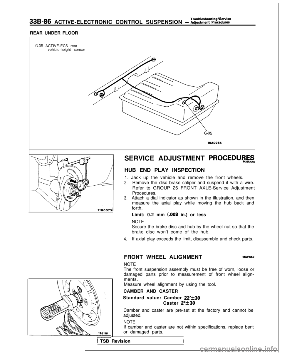
REAR UNDER FLOOR
G-05 ACTIVE-ECS rear vehicle-height sensor
16A0266
SERVICE ADJUSTMENT PROCEDURAZ
HUB END PLAY INSPECTION
1. Jack up the vehicle and remove the front wheels.
2.Remove the disc brake caliper and suspend it with a wire.
Refer to GROUP 26 FRONT AXLE-Service Adjustment
Procedures.
3.Attach a dial indicator as shown in the illustration, and then measure the axial play while moving the hub back and
forth.
Limit: 0.2 mm t.008
in.) or less
NOTE
Secure the brake disc and hub by the wheel nut so that the
brake disc won’t come of the hub.
4.If axial play exceeds the limit, disassemble and check parts.
FRONT WHEEL ALIGNMENT
M33f6AD
NOTE
The front suspension assembly must be free of worn, loose or
damaged parts prior to measurement of front wheel align- ments.
Measure wheel alignment by using the tool.
CAMBER AND CASTER
Standard value: Camber
22’f30
Caster ZY30
Camber and caster are pre-set at the factory and cannot be
adjusted.
NOTE
If camber and caster are not within specifications, replace bent
or damaged parts.
I TSB RevisionI
Page 1038 of 1273
ACTIVE-ELECTRONIC CONTROL SUSPENSION - Strut Assembly33B-99
12Ao291
Strutator
a
.
Front
12AO.0003
Apply rubber grease
WA0327
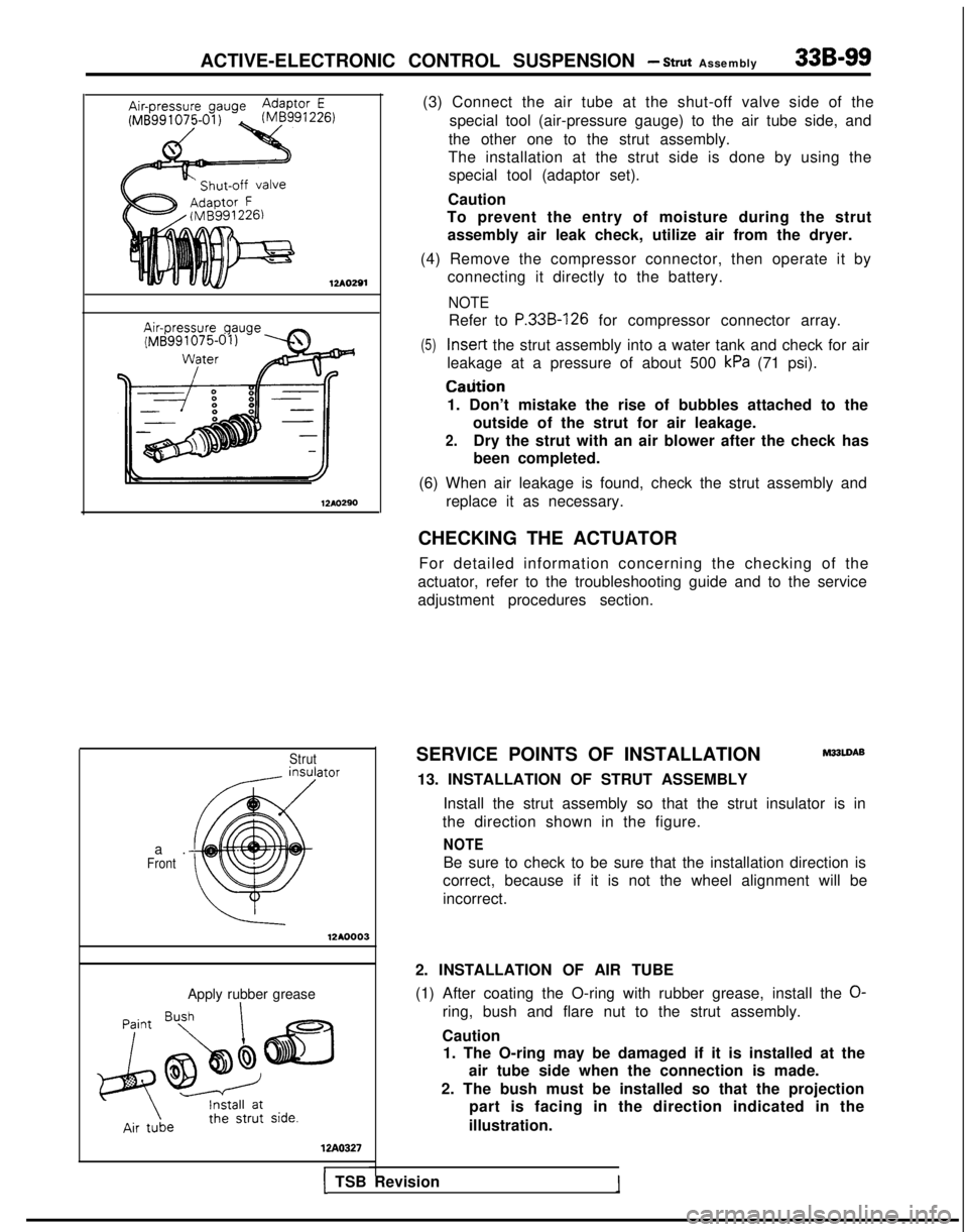
(3) Connect the air tube at the shut-off valve side of the
special tool (air-pressure gauge) to the air tube side, and
the other one to the strut assembly.
The installation at the strut side is done by using the special tool (adaptor set).
Caution
To prevent the entry of moisture during the strut
assembly air leak check, utilize air from the dryer.
(4) Remove the compressor connector, then operate it by connecting it directly to the battery.
NOTE
Refer to P.33B-126 for compressor connector array.
(5) Insert
the strut assembly into a water tank and check for air
leakage at a pressure of about 500
kPa (71 psi). Caiition
1. Don’t mistake the rise of bubbles attached to the outside of the strut for air leakage.
2.Dry the strut with an air blower after the check has
been completed.
(6) When air leakage is found, check the strut assembly and replace it as necessary.
CHECKING THE ACTUATOR For detailed information concerning the checking of the
actuator, refer to the troubleshooting guide and to the service
adjustment procedures section.
SERVICE POINTS OF INSTALLATION
M33LDAB
13. INSTALLATION OF STRUT ASSEMBLY Install the strut assembly so that the strut insulator is in
the direction shown in the figure.
NOTE
Be sure to check to be sure that the installation direction is
correct, because if it is not the wheel alignment will be
incorrect.
2. INSTALLATION OF AIR TUBE
(1) After coating the O-ring with rubber grease, install the
O-
ring, bush and flare nut to the strut assembly.
Caution 1. The O-ring may be damaged if it is installed at the
air tube side when the connection is made.
2. The bush must be installed so that the projection part is facing in the direction indicated in the
illustration.
1 TSB Revision
Page 1082 of 1273
34-1
REAR
SUSPENSION
CONTENTSM%AA-
REARSUSPENSION
ASSEMBLY..................24
SERVICE ADJUSTMENT PROCEDURES..
.....23
Rear Wheel AlignmentInspection...............23
SHOCK
ABSORBERASSEMBLY...................35
SPECIAL TOOLS .............................................
21
SPECIFICATIONS.............................................19
GeneralSpecifications
..................................19
ServiceSpecifications ...................................19
TorqueSpecifications ...................................20
STABILIZER BAR .............................................
37
TRAILING ARM...............................................31
TROUBLESHOOTING......................................
22
UPPERANDLOWERARM............................28
LATERAL ROD.................................................14
REAR
SUSPENSIONASSEMBLY..................6
SERVICE ADJUSTMENT PROCEDURES.......5
Rear Wheel Alignment Inspection ...............5
SHOCKABSORBER
ASSEMBLY...................11
SPECIALTOOLS.............................................4
SPECIFICATIONS ............................................. 2
General Specifications
..................................2
Service
Specifications ...................................
TorqueSpecifications ...................................
TORSION AXLE AND ARM ASSEMBLY..
.... 15
TROUBLESHOOTING ......................................5
Page 1086 of 1273
REAR SUSPENSION
TROUBLESHOOTING
M34EAA
Symptom Probable cause( Remedy
Squeaks or other
abnormal noise Loose rear suspension installation bolts and nuts
Retighten
IMalfunction of shock absorber
Worn bushingsReplace
Poor ride
Excessive tire inflation pressureIAdjust the pressure
Malfunction of shock absorber
Weak or broken springs
Replace
Body tilting Weak or deteriorated bushings
Weak or broken springsReplace
TSB Revision
SERVICE ADJUSTMENT PROCEDUEZ$
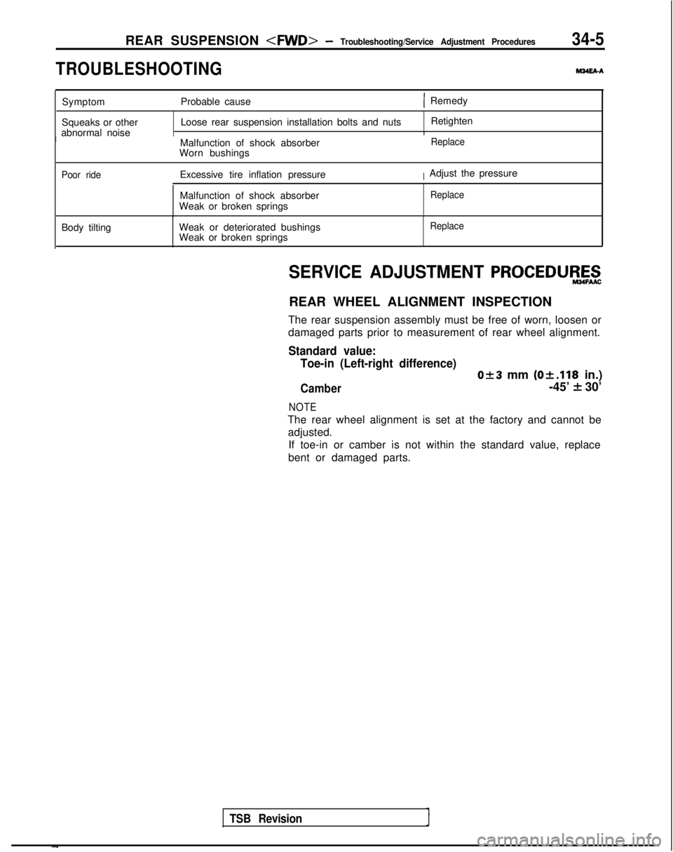
REAR WHEEL ALIGNMENT INSPECTION
The rear suspension assembly must be free of worn, loosen or
damaged parts prior to measurement of rear wheel alignment.
Standard value: Toe-in (Left-right difference)
0+3 mm (Ok.118
in.)
Camber-45’ f 30’
NOTE
The rear wheel alignment is set at the factory and cannot be
adjusted. If toe-in or camber is not within the standard value, replace
bent or damaged parts.
Page 1104 of 1273
REAR SUSPENSION
12AOO83
12A0081
SERVICE ADJUSTMENT. PROCEDURES
REAR WHEEL ALIGNMENT INSPECTION mm
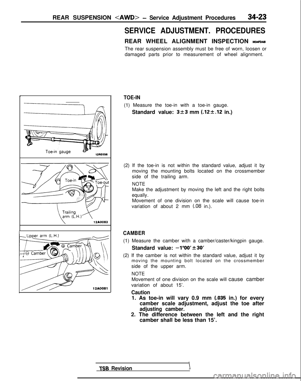
The rear suspension assembly must be free of worn, loosen or
damaged parts prior to measurement of wheel alignment.
TOE-IN
(1) Measure the toe-in with a toe-in gauge.
Standard value:
3+3 mm (.12+.12 in.)
(2) If the toe-in is not within the standard value, adjust it by moving the mounting bolts located on the crossmember
side of the trailing arm.
NOTE
Make the adjustment by moving the left and the right bolts
equally.
Movement of one division on the scale will cause toe-in
variation of about 2 mm
(.08 in.).
CAMBER
(1) Measure the camber with a camber/caster/kingpin gauge.
Standard value:
-1”OO’f30’
(2) If the camber is not within the standard value, adjust it bymoving the mounting bolt located on the crossmember
side of the upper arm.
NOTE
Movement of one division on the scale will cause camber
variation of about 15’.
Caution
1. As toe-in will vary 0.9 mm LO35 in.) for every
camber scale adjustment, adjust the toe after
adjusting camber.
2. The difference between the left and the right camber shall be less than 15’.
TSB Revision \