1989 MITSUBISHI GALANT fuel pressure
[x] Cancel search: fuel pressurePage 76 of 1273
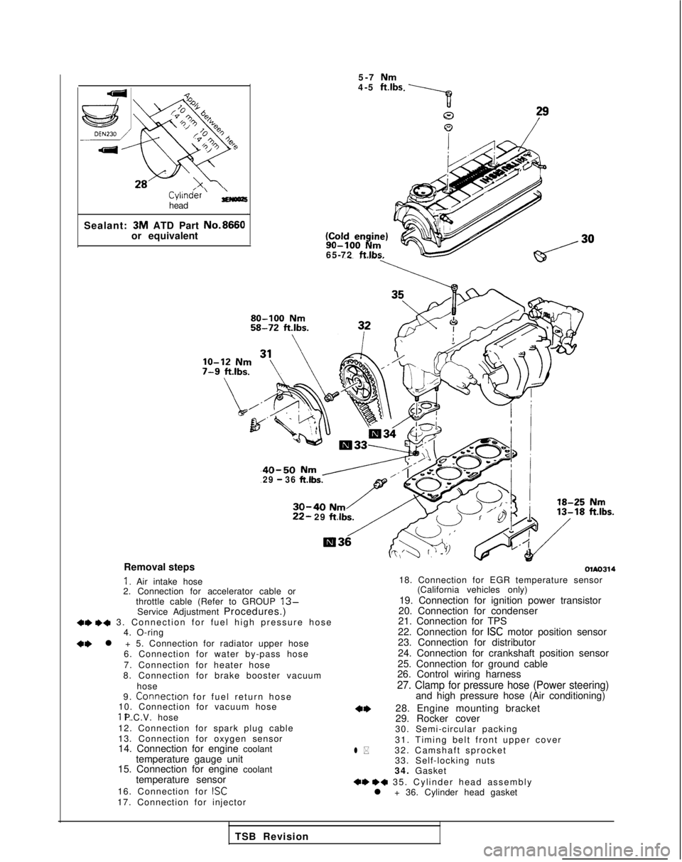
Cyl1n&r’ ;;(oozhead
Sealant: 3M
ATD Part No.8660
or equivalent 5-7
Nm4-5 ft.lbs 90-100
Nm65-72 ftlbs.
40-50 Nm /29 - 36 ft.lbs.
30-40 Nm22- 29
ftlbs.
Removal steps
I. Air intake hose
2. Connection for accelerator cable or
throttle cable (Refer to GROUP
13-Service Adjustment Procedures.)+e +a 3. Connection for fuel high pressure hos
e
4. O-ring
+e l + 5. Connection for radiator upper hose
6. Connection for water by-pass hose
7. Connection for heater hose
8. Connection for brake booster vacuum
hose
9.
Connectron for fuel return hos
e
10. Connection for vacuum hose 11. P.C.V. hose
12. Connection for spark plug cable
13. Connection for oxygen sensor
14. Connection for engine coolant temperature gauge unit
15. Connection for engine coolant
temperature sensor
16. Connection for
ISC17. Connection for injector
olAo314
l *
18. Connection for EGR temperature sensor (California vehicles only)
19. Connection for ignition power transistor
20. Connection for condenser
21. Connection for TPS
22. Connection for
ISC motor position sensor
23. Connection for distributor
24. Connection for crankshaft position sensor
25. Connection for ground cable
26. Control wiring harness
27. Clamp for pressure hose (Power steering)and high pressure hose (Air conditioning)
28. Engine mounting bracket
29. Rocker cover
30. Semi-circular packing
31. Timing belt front upper cover
32. Camshaft sprocket 33. Self-locking nuts
34. Gasket
+e ++ 35. Cylinder head assembl
y
l + 36. Cylinder head gasket
TSB Revision
Page 77 of 1273
ENGINE
\
r
MatingC
-I
1
J-1.‘T
:-c’ 000510020
SERVICE POINTS OF REMOVALMllJBAl
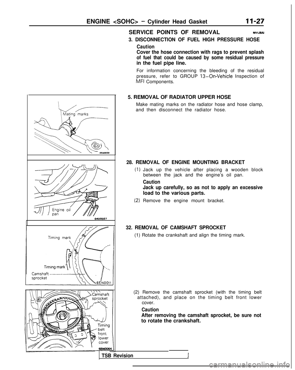
3. DISCONNECTION OF FUEL HIGH PRESSURE HOSE
Caution
Cover the hose connection with rags to prevent splash
of fuel that could be caused by some residual pressure
in the fuel pipe line.
For information concerning the bleeding of the residual
pressure, refer to GROUP
13-On-Vehicle Inspection of
MFI
Components.
5. REMOVAL OF RADIATOR UPPER HOSE Make mating marks on the radiator hose and hose clamp,
and then disconnect the radiator hose.
28. REMOVAL OF ENGINE MOUNTING BRACKET
Jack up the vehicle after placing a wooden block between the jack and the engine’s oil pan.
Caution
Jack up carefully, so as not to apply an excessive
load to the various parts.
Remove the engine mount bracket.
32. REMOVAL OF CAMSHAFT SPROCKET
(1) Rotate the crankshaft and align the timing mark.
(2) Remove the camshaft sprocket (with the timing belt attached), and place on the timing belt front lower cover.
Caution
After removing the camshaft sprocket, be sure not
to rotate the crankshaft.
TSB Revision
Page 79 of 1273
ENGINE
Front of engine I)Intake side
6EN094
Exhaust side
OlR0391
Fuel rail
pr&surehose\0-nng
TSB Revision
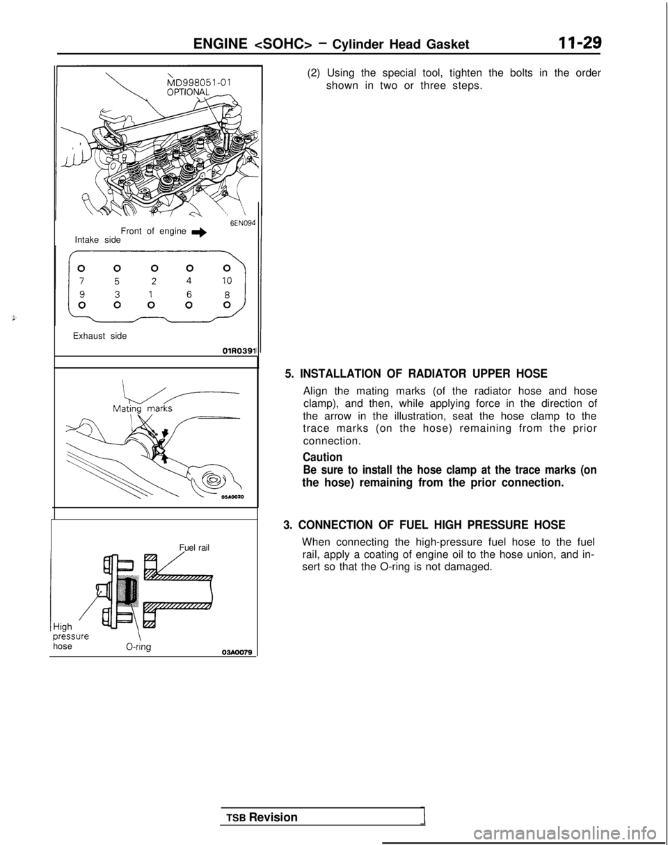
(2) Using the special tool, tighten the bolts in the order
shown in two or three steps.
5. INSTALLATION OF RADIATOR UPPER HOSE
Align the mating marks (of the radiator hose and hoseclamp), and then, while applying force in the direction of
the arrow in the illustration, seat the hose clamp to the
trace marks (on the hose) remaining from the prior connection.
Caution Be sure to install the hose clamp at the trace marks (on
the hose) remaining from the prior connection.
3. CONNECTION OF FUEL HIGH PRESSURE HOSE
When connecting the high-pressure fuel hose to the fuel rail, apply a coating of engine oil to the hose union, and in-
sert so that the O-ring is not damaged.
Page 80 of 1273
II-30ENGINE
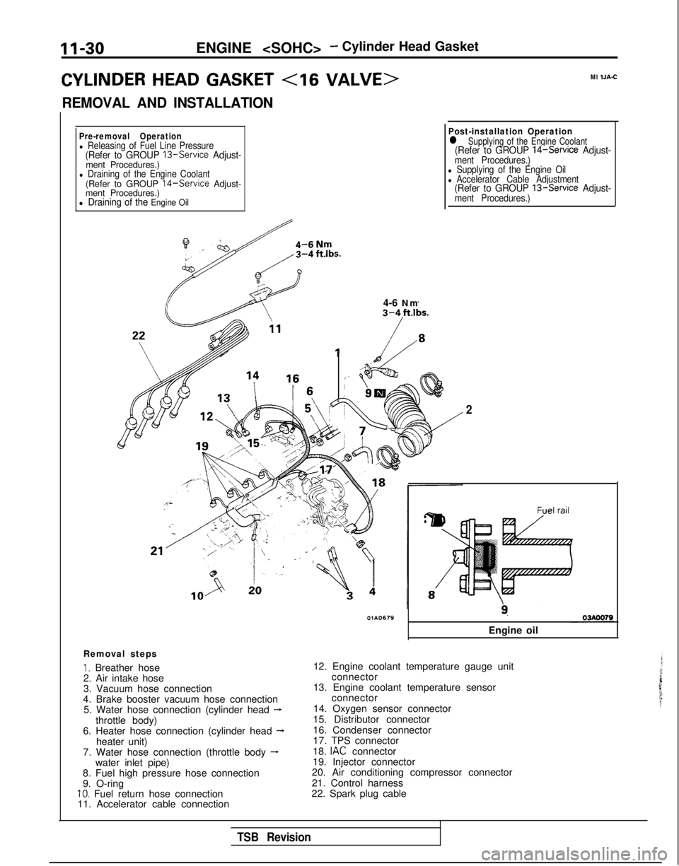
CYLINDER HEAD GASKET
REMOVAL AND INSTALLATION
Ml IJA-C
Pre-removal Operationl Releasing of Fuel Line Pressure(Refer to GROUP 13-Service Adjust-ment Procedures.)l Draining of the Engine Coolant(Refer to GROUP 14-Service Adjust-
ment Procedures.)
l Draining of the Engine Oil
il4-6 Nm
Post-installation Operationl Supplying of the Engine Coolant(Refer to GROUP 14-Service Adjust-ment Procedures.)l Supplying of the Engine Oill Accelerator Cable Adjustment(Refer to GROUP 13-Service Adjust-ment Procedures.)
Removal steps
I. Breather hose
2. Air intake hose
3. Vacuum hose connection
4. Brake booster vacuum hose connection 5. Water hose connection (cylinder head
-throttle body)
6. Heater hose connection (cylinder head --Lheater unit)
7. Water hose connection (throttle body -water inlet pipe)
8. Fuel high pressure hose connection
9. O-ring
10. Fuel return hose connection
11. Accelerator cable connection
2
9.
Engine oil
12. Engine coolant temperature gauge unit connector
13. Engine coolant temperature sensor connector
14. Oxygen sensor connector
15. Distributor connector
16. Condenser connector
17. TPS connector
18.
IAC connector
19. Injector connector
20. Air conditioning compressor connector
21. Control harness
22. Spark plug cable
TSB Revision
Page 104 of 1273
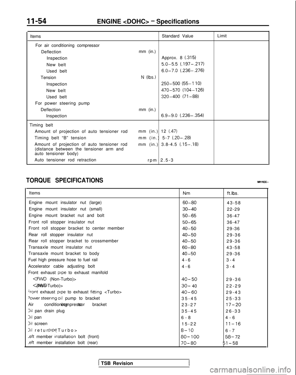
11-54ENGINE
Items For air conditioning compressor DeflectionInspection
New belt
Used belt
Tension
Inspection
New belt
Used belt
For power steering pump
DeflectionInspection
Timing belt Amount of projection of auto tensioner rod
Timing belt “B” tension
Amount of projection of auto tensioner rod (distance between the tensioner arm and
auto tensioner body)
Auto tensioner rod retraction Standard Value
mm (in.) Approx. 8
(.315)
5.0-5.5 (.197-,217)
6.0-7.0 (.236-.276)
N (Ibs.)
250-500 (55-l 10)
470-570 (104-126)
320-400 (71-88)
mm (in.)
6.9-9.0 (.236-,354)
mm (in.) 12 (.47)
mm (in.) 5-7 (.20-.28)
mm (in.) 3.8-4.5 (.15-.18)
rpm 2.5-
3
Limit
TORQUE SPECIFICATIONS
Items
Engine mount insulator nut (large)
Engine mount insulator nut (small)
Engine mount bracket nut and bolt
Front roll stopper insulator nut
Front roll stopper bracket to center member
Rear roll stopper insulator nut
Rear roll stopper bracket to crossmember
Transaxle mount insulator nut
Transaxle mount bracket to body
Fuel high pressure hose to fuel rail
Accelerator cable adjusting bolt
Front exhaust
pope to exhaust manifold
+ont exhaust pope to exhaust fitting
‘ower steerrng 011 pump to bracket
Air conditioning to bracket compressor311
pan drain plug
311 pan
3il screen
111 return (Turbo
>
pope
.eft
member installation
bolt (front)
-eft member installation bolt (rear) Nm
ft.ibs.
60-8043-5
8
30-4022-29
50-6536-47
50-6536-47
40-5029-36
40-5029-3
6
40-5029-3
6
60-8043-5
8
40-5029-3
6
4-6 3-4
4-6 3-4
40-5029-3
6
30- 40
22-2
9
40-6029-4
3
35-45 25-33
23-27
17-20
35-4
5
26-33
6-8 4-6
15-22
11-16
8-106-
7
80-
10058- 72
70-8051-58
MllCC--
( TSB Revision
Page 109 of 1273
ENGINE
7 Go;;ikv position
switch
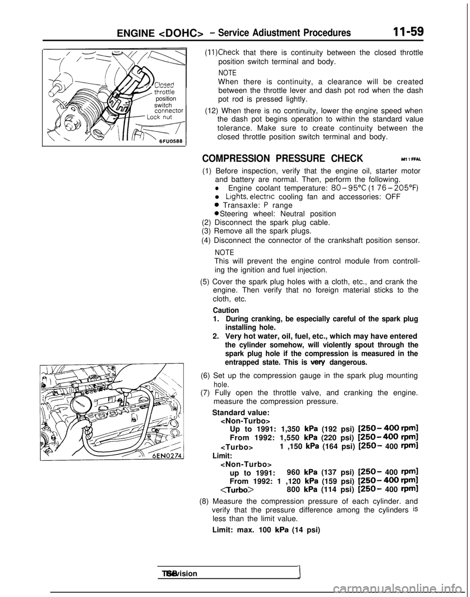
(11)Check that there is continuity between the closed throttle
position switch terminal and body.
NOTE
When there is continuity, a clearance will be created between the throttle lever and dash pot rod when the dash
pot rod is pressed lightly.
(12) When there is no continuity, lower the engine speed when the dash pot begins operation to within the standard value
tolerance. Make sure to create continuity between the
closed throttle position switch terminal and body.
COMPRESSION PRESSURE CHECK Ml 1 FFAL
(1) Before inspection, verify that the engine oil, starter motor
and battery are normal. Then, perform the following.
lEngine coolant temperature: 80- 95°C
(1 76- 205’F)
l Lights, electnc
cooling fan and accessories: OFF
0 Transaxle: P range 0 Steering wheel: Neutral position
(2) Disconnect the spark plug cable.
(3) Remove all the spark plugs.
(4) Disconnect the connector of the crankshaft position sensor.
NOTE
This will prevent the engine control module from controll- ing the ignition and fuel injection.
(5) Cover the spark plug holes with a cloth, etc., and crank the engine. Then verify that no foreign material sticks to the
cloth, etc.
Caution
1.During cranking, be especially careful of the spark plug
installing hole.
2. Very hot water, oil, fuel, etc., which may have entered
the cylinder somehow, will violently spout through the
spark plug hole if the compression is measured in the
entrapped state. This is
vex/ dangerous.
(6) Set up the compression gauge in the spark plug mounting
hole.
(7) Fully open the throttle valve, and cranking the engine.
measure the compression pressure.
Standard value:
kPa (192 psi) [250- 400 rpml
From 1992: 1,550
kPa (220 psi) [250-400 rpm]
Limit:
up to 1991: 960
kPa (137 psi) [250- 400 rpml
From 1992: 1 ,120 kPa (159 psi) [250- 400 rpml
CTurbo>
800
kPa (114 psi) [250- 400 rpml
(8) Measure the compression pressure of each cylinder. and verify that the pressure difference among the cylinders
is
less than the limit value.
Limit: max. 100
kPa (14 psi) TSB Revision
I
Page 110 of 1273
II-60ENGINE
(9) If a cylinder’s compression pressure or pressure differenceis outside the limit, fill a small amount of engine oil through
the spark plug hole and repeat Items (7) and (8) above.
@ If the compression is increased when the oil is filled, the piston
and/or cylinder wall may be worn or
damaged.
@ If the compression is not Increased even though the oil is filled, the valve may be thermally seized, the valve
contact may be improper or pressure may leak at the
gasket. (10)Connect the connector of the crankshaft position sensor.
(1l)lnstall
the spark plug and spark plug cable.
(12)Erase the diagnostic trouble code with the scan tool or re-
connect the battery (-)
cable 10 seconds or more after it
was disconnected.
NOTE
This will erase the memory of the diagnostic trouble code which resulted from disconnection of the crankshaft posi-
tion sensor connector.
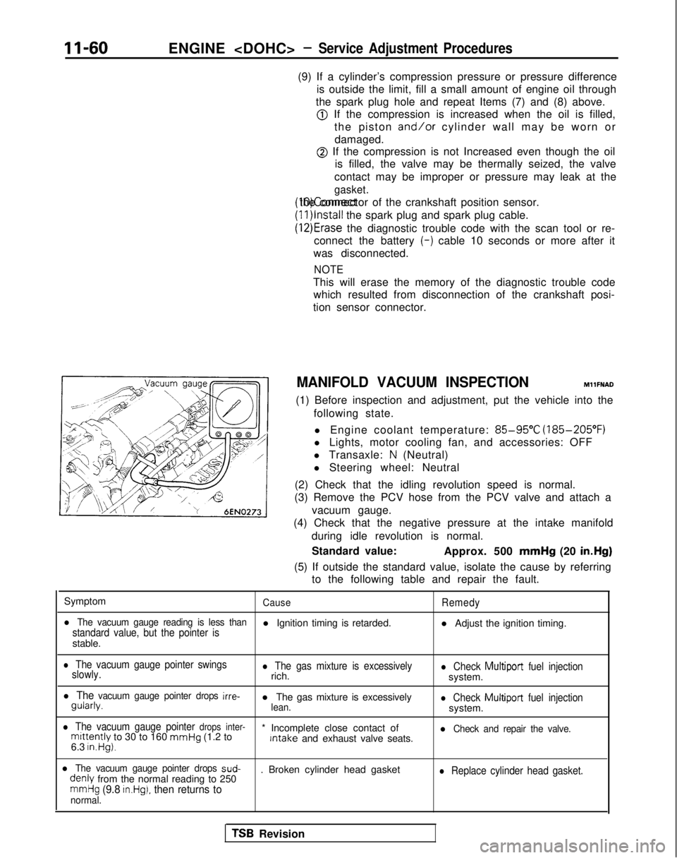
MANIFOLD VACUUM INSPECTION MllFNAD
(1) Before inspection and adjustment, put the vehicle into the following state.
l Engine coolant temperature:
85-95°C (185-205°F)
l Lights, motor cooling fan, and accessories: OFF
l Transaxle:
N (Neutral)
l Steering wheel: Neutral
(2) Check that the idling revolution speed is normal.
(3) Remove the PCV hose from the PCV valve and attach a
vacuum gauge.
(4) Check that the negative pressure at the intake manifold
during idle revolution is normal.
Standard value: Approx. 500 mmHg
(20 in.Hg)
(5) If outside the standard value, isolate the cause by referring to the following table and repair the fault.
Symptom
CauseRemedy
l The vacuum gauge reading is less thanstandard value, but the pointer isl Ignition timing is retarded. l Adjust the ignition timing.
stable.
l The vacuum gauge pointer swings
slowly.l The gas mixture is excessivelyrich.l Check Multiport fuel injectionsystem.
l The vacuum gauge pointer drops irre- gularly.
l The gas mixture is excessively
lean.l Check Multiport
fuel injectionsystem.
l The vacuum gauge pointer drops inter-mittently to 30 to 160 mmHg
(1.2 to * Incomplete close contact of Intake
and exhaust valve seats.l Check and repair the valve.
6.3 in.Hg).
l The vacuum gauge pointer drops sud- denly
from the normal reading to 250 . Broken cylinder head gasketl Replace cylinder head gasket.
mmHg (9.8 in.Hg), then returns tonormal.
TSB Revision
Page 113 of 1273
ENGINE
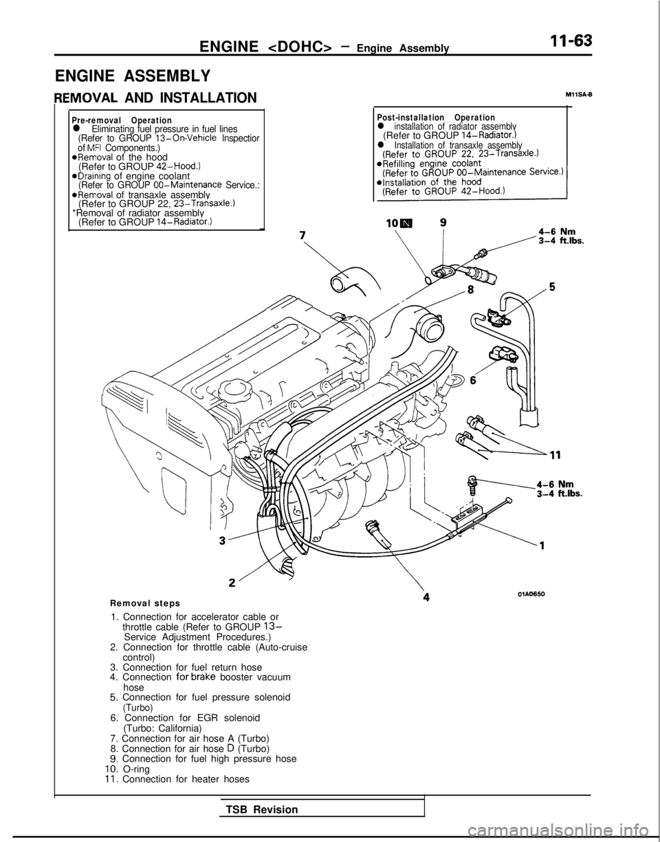
ENGINE ASSEMBLY
IEMOVAL AND INSTALLATION
Pre-removal Operationl Eliminating fuel pressure in fuel lines
(Refer to GROUP 13-On-Vehicle lnspectior
of MFI Components.)*Removal of the hood
(Refer to GROUP 42-Hood.)
eDraining of engine coolant(Refer to GROUP 00-Maintenance
Service.:@Removal of transaxle assembly
(Refer to GROUP 22, 23-Transaxle.)*Removal of radiator assembly
(Refer to GROUP 14-Radiator.)
MIISA-6
Post-installation Operationl installation of radiator assembly(Refer to GROUP 14-Radiator.)l Installation of transaxle assembly
Removal steps
1. Connection for accelerator cable or throttle cable (Refer to GROUP
13-Service Adjustment Procedures.)
2. Connection for throttle cable (Auto-cruise control)
3. Connection for fuel return hose
4. Connection
forbrake booster vacuum
hose
5. Connection for fuel pressure solenoid(Turbo)6. Connection for EGR solenoid (Turbo: California)
7. Connection for air hose A (Turbo) 8. Connection for air hose
D (Turbo)9. Connection for fuel high pressure hose10. O-ring11. Connection for heater hoses
TSB Revision