1989 MITSUBISHI GALANT fuel pressure
[x] Cancel search: fuel pressurePage 173 of 1273
FUEL SYSTEM
MFIRELAY
IIOXYGEN SENSOR(VEHICLES FORCALIFORNIA)
g k______ -___----__ -------------
mlI
----518>
EF
!, -I
s A-08c-09
f@p&g~,,-yg@
POWER STEERINGPRESSURE SWITCH
.
---
-
1
3
14
--
-
3
1-
I
_------3
15
P
10
I [
12 t-----58
(ENG)
(DATA)
c-40-0
3
1
2
1
C-38
DATA LINKCONTROL MOTORCONNECTOR
' OXYGEN SENSOR'(VEHICLES FOR
1 TSB RevisionI
Page 174 of 1273
13-32
FUEL SYSTEM
FUEL TANK AND FUEL LINEMlBEAAA
Symptom Probable cause Remedy
Engtne malfunctions
Bent or kinked fuel pipe or hose Repair or replace3ue to insufficient fuel
SUPPlYClogged fuel pipe or hoseClean or replace
Clogged fuel filter or in-tank fuel filter Replace
Water in fuel filter Replace the fuel filter or clean the fuel tank
and fuel line
Dirty or rusted fuel tank interior Malfunctioning fuel pump
(Clogged filter in the pump) Clean or replace
Replace
Evaporative emission Mispiping of vapor line
Correct
control system malfunc-
tions (When fuel tank Disconnect vapor line piping joint Correct
filler tube cap is re- moved, pressure releas-
Folded, bent, cracked or clogged vapor line Replace
ng noise is heard) Faulty fuel tank filler tube cap
Malfunctioning fuel tank pressure control
valve Replace
Replace
LL
m ~~ : Paper clip-
F l!;“I /yFp- -
izd--_7-01
A0086SERVICE ADJUSTMENT PROCEDURES
CURB IDLE SPEED INSPECTION
MlBFHAFt
(1) The vehicle should be prepared as follows before the inspection.
lEngine coolant temperature: 85-95°C (185-203°F)
l Lights, electric cooling fan and accessories: OFF
l Transaxle: Neutral
(P for vehicles with an automatic
transaxle)
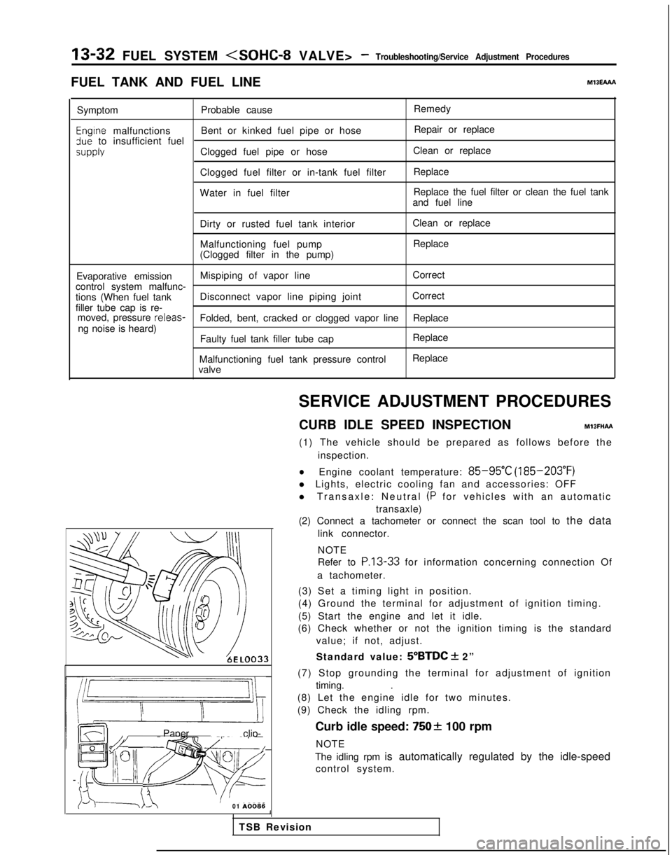
(2) Connect a tachometer or connect the scan tool to the data
link connector.
NOTE
Refer to
P.13-33 for information concerning connection Of
a tachometer.
(3) Set a timing light in position.
(4) Ground the terminal for adjustment of ignition timing.
(5) Start the engine and let it idle.
(6) Check whether or not the ignition timing is the standard
value; if not, adjust.
Standard value:
5”BTDC + 2”
(7) Stop grounding the terminal for adjustment of ignition timing. .
(8) Let the engine idle for two minutes.
(9) Check the idling rpm.
Curb idle speed:
7502 100 rpm
NOTE
The idling rpm is automatically regulated by the idle-speed control system.
1
TSB Revision
Page 180 of 1273
13-38
FUEL SYSTEM
ON-VEHICLE INSPECTION OF MFI
COMPONENTS
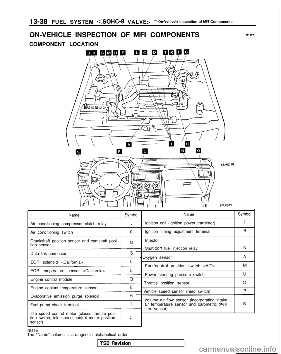
COMPONENT LOCATION
Ii111 I‘I 1 II
bEM0148
6FUO843
M?BYA-
Name Symbol Name
Symbol
Air conditioning compressor clutch relay
JIgnition coil (ignition power transistor)F
Air conditioning switch 0Ignition timing adjustment terminalR
Crankshaft position sensor and camshaft posi- InjectorIGtion sensor-Multiport fuel injection relayN
Data link connectorS - Oxygen sensor
A
EGR solenoid
K-Park/neutral position switch M
EGR temperature sensor
L-Power steering pressure switchU
Engine control moduleQ- Throttle position sensorD
Engine coolant temperature sensorE- Vehicle speed sensor (reed switch)P
Evaporative emission purge solenoidHVolume air flow sensor (incorporating intake
Fuel pump check terminalTair temperature sensor and barometric pres-B
-sure sensor)
Idle speed control motor (closed throttle posi-
tion switch, idle speed control motor position
Csensor)
NOTEThe “Name” column is arranged in alphabetical order
TSB Revision
Page 191 of 1273
FUEL SYSTEM
VOLUME AIR FLOW SENSOR
@ ;;vonent
connector
Intake air amount
(Wsec)162451
Multipoh fuel
injection relay
Volume air flow sensor
/\2/\N
Harness side
connector
IHjhcillo)
1.10
f-i5V
Engine
control
module
MlOYFAA
J 6FU1394
OPERATION
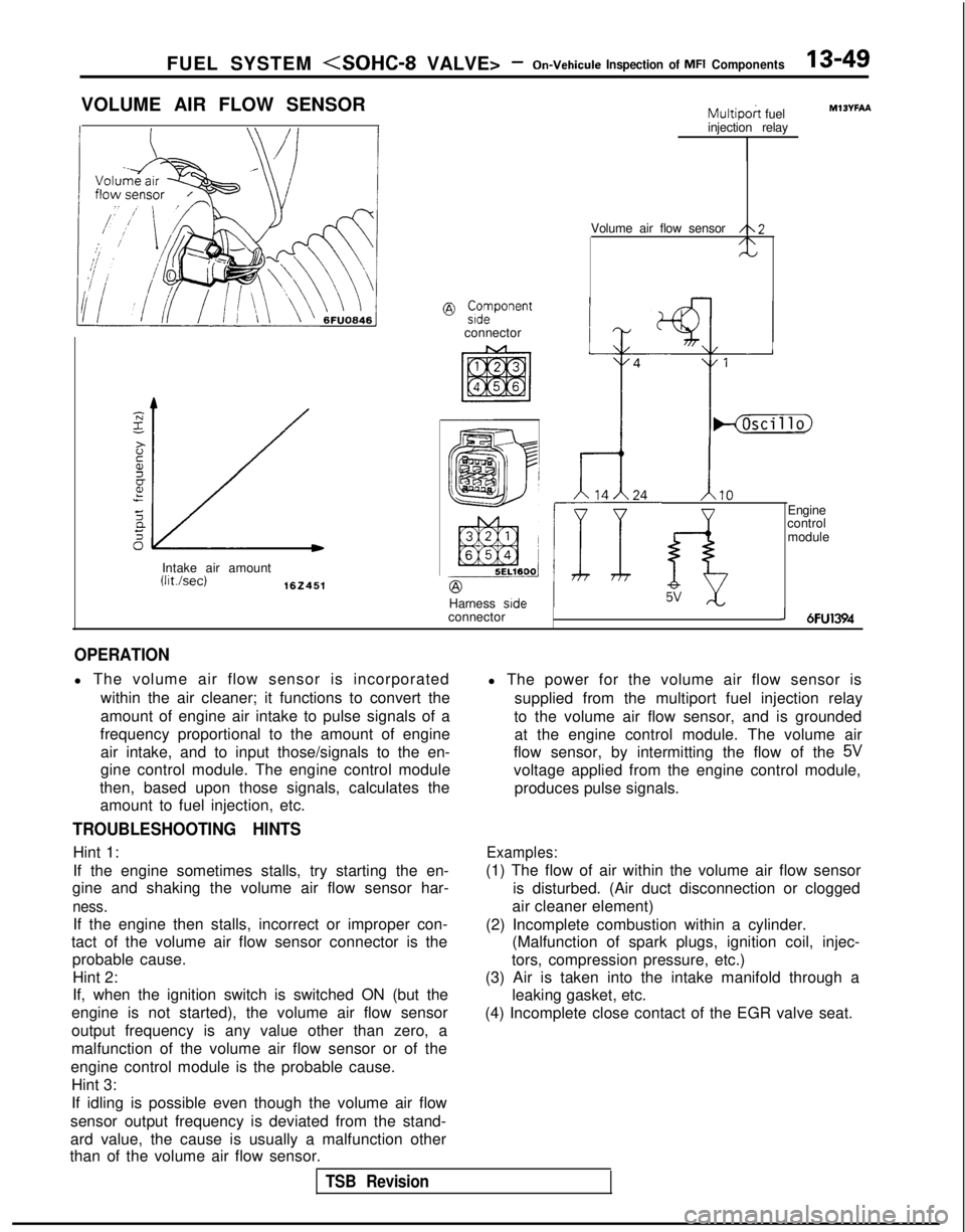
l The volume air flow sensor is incorporated
within the air cleaner; it functions to convert the
amount of engine air intake to pulse signals of a
frequency proportional to the amount of engine air intake, and to input those/signals to the en-
gine control module. The engine control module
then, based upon those signals, calculates the amount to fuel injection, etc.
TROUBLESHOOTING HINTS
Hint 1:
If the engine sometimes stalls, try starting the en-
gine and shaking the volume air flow sensor har-
ness.
If the engine then stalls, incorrect or improper con-
tact of the volume air flow sensor connector is the probable cause.
Hint 2:
If, when the ignition switch is switched ON (but the
engine is not started), the volume air flow sensor
output frequency is any value other than zero, a
malfunction of the volume air flow sensor or of the
engine control module is the probable cause. Hint 3:
If idling is possible even though the volume air flow
sensor output frequency is deviated from the stand-
ard value, the cause is usually a malfunction other
than of the volume air flow sensor. l The power for the volume air flow sensor is
supplied from the multiport fuel injection relay
to the volume air flow sensor, and is grounded at the engine control module. The volume air
flow sensor, by intermitting the flow of the
5V
voltage applied from the engine control module,
produces pulse signals.
Examples:
(1) The flow of air within the volume air flow sensor is disturbed. (Air duct disconnection or clogged
air cleaner element)
(2) Incomplete combustion within a cylinder. (Malfunction of spark plugs, ignition coil, injec-
tors, compression pressure, etc.)
(3) Air is taken into the intake manifold through a leaking gasket, etc.
(4) Incomplete close contact of the EGR valve seat.
TSB Revision
Page 195 of 1273
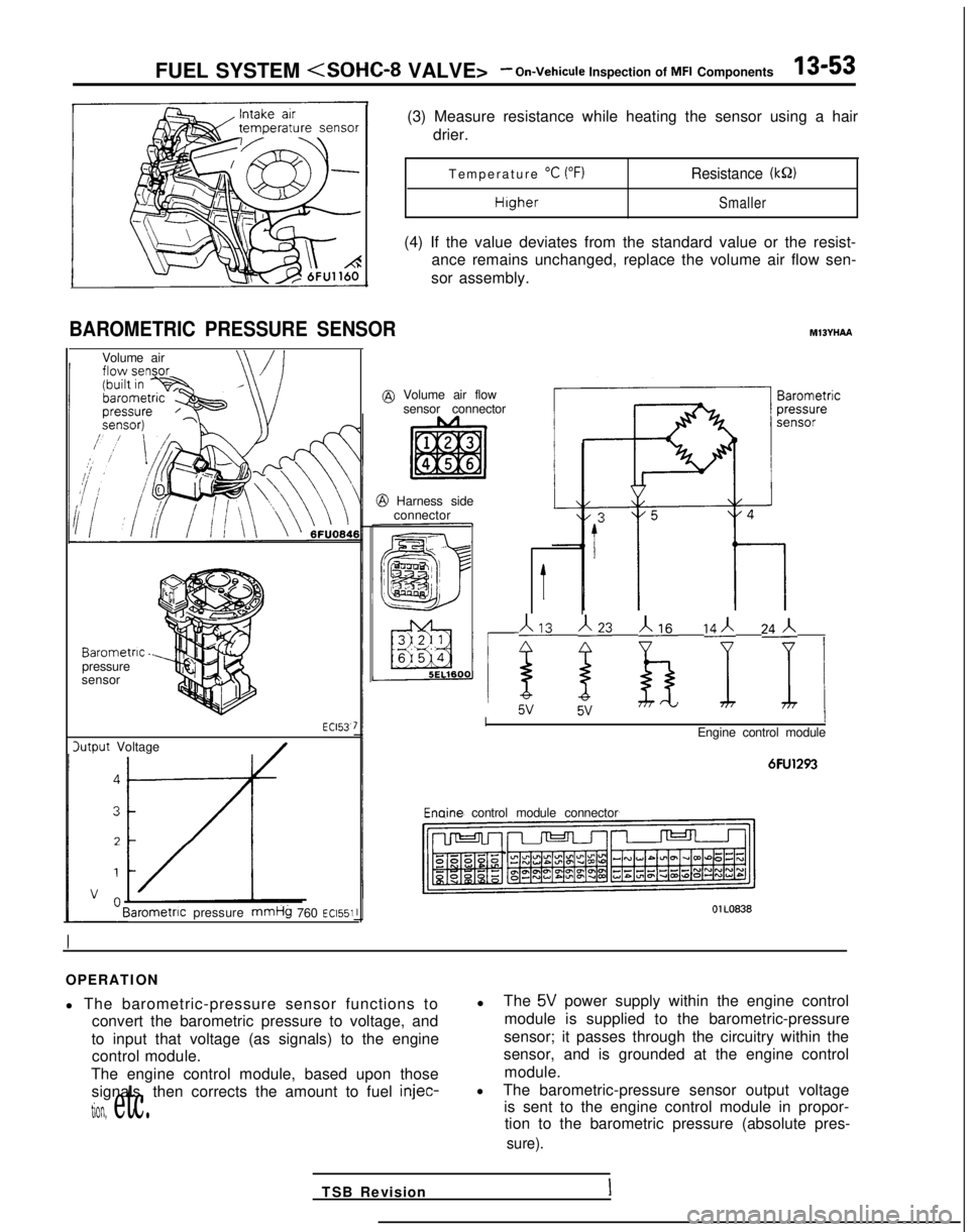
FUEL SYSTEM
BAROMETRIC PRESSURE SENSOR
Volume air
Barometric.pressure
sensor
lutput Voltage ECl53.
Barometnc
pressure
mmHg 760 ~~1551
(3) Measure resistance while heating the sensor using a hair
drier.
Temperature
“C (“F)Resistance (kQ)
HigherSmaller
(4) If the value deviates from the standard value or the resist-
ance remains unchanged, replace the volume air flow sen-
sor assembly.
MlBYHAA
@ Volume air flow sensor connector
@ Harness sideconnector
t
113 j23 b ‘I 24j i
IEngine control module
6FU1293 Enaine
control module connector
OlL0838
OPERATION
l The barometric-pressure sensor functions to
convert the barometric pressure to voltage, and
to input that voltage (as signals) to the engine control module.
The engine control module, based upon those signals, then corrects the amount to fuel injec-
tion, etc.
l
The 5V power supply within the engine control
module is supplied to the barometric-pressure
sensor; it passes through the circuitry within the
sensor, and is grounded at the engine control
module.
l The barometric-pressure sensor output voltage
is sent to the engine control module in propor-tion to the barometric pressure (absolute pres-
sure).
TSB RevisionI
Page 196 of 1273
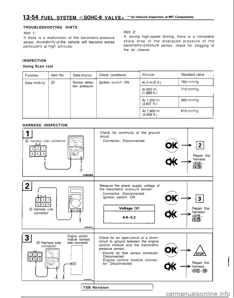
13-54 FUEL SYSTEM
TROUBLESHOOTING HINTS Hint 1: Hint 2:
If there is a malfunction of the barometric-pressure If, during high-speed driving, there is a noticeable
sensor,
driveability of the vehicle will become worse sharp drop of the displayed pressure of th
e
barometric-rxessure sensor, check for clogging ofparticularly at hig’h altitude
.
the air cleaner.
INSPECTION Using Scan tool
AltitudeStandard valueICheck conditions
Item No. Data display
25Sensor detec-
tion pressure
Function
Data reading
Ignition switch: ON
At 0 m (0 ft.) 760 mmHg
At 600
m(1,969ft.j710 mmHg
I
At 1,200 m660
mmHg(3,937
ft.)
At 1,800
m(5,906 ft.) 610 mmHgI
HARNESS INSPECTION
Check for continuity of the ground
circuit.
. Connector: Disconnected
connector
L,?
la
Fi
gg-CI
e
Repair the
harness.
KBEil-IBHZI)
Measure the power supply voltage of
the barometric oressure
sensor.
. Connector: Disconnected
. Ignition switch: ON
Harness side
connector
Check for an open-circuit or a short-circuit to ground between the engine
control module and the barometric pressure sensor.
f Volume air flow sensor connector: Disconnected
Engine control
module harness
@ Harness sideside connector
Engine control module connec-
tor: Disconnected Repair the
harness.
ozsEl-~)
1 TSB Revision
Page 197 of 1273
FUEL SYSTEM
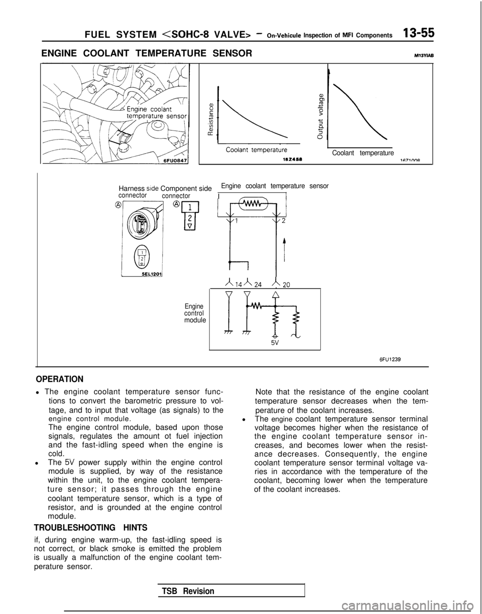
ENGINE COOLANT TEMPERATURE SENSORMl3wAB
Coolant-
tempera&Coolant temperature
Harness side Component sideEngine coolant temperature sensorIconnector
connectorI -
15EL12011I IA14”24A20
Engine
control
module
If9-3 5v
6FU1239
OPERATION
l The engine coolant temperature sensor func-
tions to convert the barometric pressure to vol-
tage, and to input that voltage (as signals) to the
engine control module.
The engine control module, based upon those
signals, regulates the amount ot fuel injection
and the fast-idling speed when the engine is
cold.
l The 5V power supply within the engine control
module is supplied, by way of the resistance
within the unit, to the engine coolant tempera-
ture sensor; it passes through the engine
coolant temperature sensor, which is a type ofresistor, and is grounded at the engine control
module.
TROUBLESHOOTING HINTS
if, during engine warm-up, the fast-idling speed is
not correct, or black smoke is emitted the problem
is usually a malfunction of the engine coolant tem-
perature sensor. Note that the resistance of the engine coolant
temperature sensor decreases when the tem-
perature of the coolant increases.
l The engine coolant temperature sensor terminal
voltage becomes higher when the resistance of
the engine coolant temperature sensor in-
creases, and becomes lower when the resist-
ance decreases. Consequently, the engine
coolant temperature sensor terminal voltage va- ries in accordance with the temperature of the
coolant, becoming lower when the temperature
of the coolant increases.
TSB Revision
Page 207 of 1273
FUEL SYSTEM
(1) Improper adjustment of the basic idling speed.
(2) Deposits adhering to the ttirottle valve.
(3) Air being taken into the intake manifold due to a gasket leak, etc.
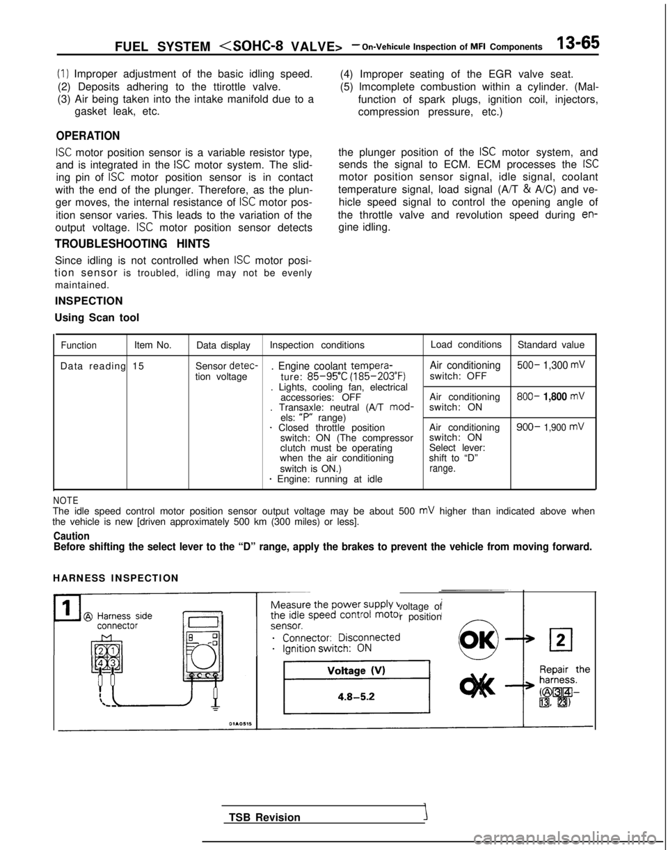
OPERATION
ISC motor position sensor is a variable resistor type,
and is integrated in the
ISC motor system. The slid-
ing pin of
ISC motor position sensor is in contact
with the end of the plunger. Therefore, as the plun- ger moves, the internal resistance of
ISC motor pos-
ition sensor varies. This leads to the variation of the (4) Improper seating of the EGR valve seat.
(5) lmcomplete combustion within a cylinder. (Mal-
function of spark plugs, ignition coil, injectors,
compression pressure, etc.)
the plunger position of the
ISC motor system, and
sends the signal to ECM. ECM processes the
ISC
motor position sensor signal, idle signal, coolant
temperature signal, load signal (A/T &
A/C) and ve-
hicle speed signal to control the opening angle of
the throttle valve and revolution speed during
en-
output voltage. ISC motor position sensor detects gine idling.
TROUBLESHOOTING HINTS
Since idling is not controlled when ISC motor posi-
tion sensor is troubled, idling may not be evenly
maintained.
INSPECTION
Using Scan tool
FunctionItem No. Data display Inspection conditions Load conditions
Standard value
Data reading 15 Sensor detec-
. Engine coolant tempera-
Air conditioning 500- 1,300 mV
tion voltage
ture: 85-95’C (185-203°F)
switch: OFF
. Lights, cooling fan, electrical accessories: OFF Air conditioning 800-
1,800 mV. Transaxle: neutral (A/T
mod-
switch: ON
els: “P”
range)
1 Closed throttle position Air conditioning900- 1,900 mVswitch: ON (The compressorswitch: ON
clutch must be operating Select lever:
when the air conditioning shift to “D”
switch is ON.)
range.* Engine: running at idle
NOTEThe idle speed control motor position sensor output voltage may be about\
500 mV higher than indicated above when
the vehicle is new [driven approximately 500 km (300 miles) or less].
CautionBefore shifting the select lever to the “D” range, apply the brake\
s to prevent the vehicle from moving forward.
HARNESS INSPECTION
Measure the power supply voltage of
the idle speed control motor position
ei;;;it;;sco$ected
__...._ -.-
TSB Revision