1989 FORD FIESTA weight
[x] Cancel search: weightPage 192 of 296
cylinder reservoir filler cap, then remove the
filler cap. Note that the filler cap must not be
inverted. Place a piece of plastic film over the
reservoir and seal it with an elastic band.
2Raise the vehicle on ramps, or drive it over
an inspection pit, so that working clearance
may be obtained with the full weight of the
vehicle on its roadwheels.
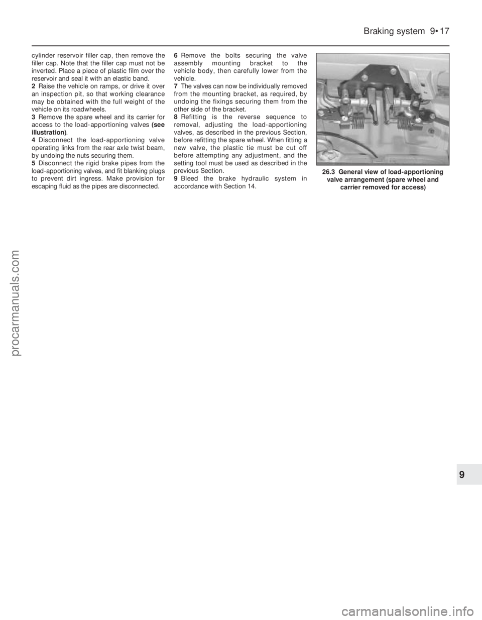
3 Remove the spare wheel and its carrier for
access to the load-apportioning valves (see
illustration) .
4 Disconnect the load-apportioning valve
operating links from the rear axle twist beam,
by undoing the nuts securing them.
5 Disconnect the rigid brake pipes from the
load-apportioning valves, and fit blanking plugs
to prevent dirt ingress. Make provision for
escaping fluid as the pipes are disconnected. 6
Remove the bolts securing the valve
assembly mounting bracket to the
vehicle body, then carefully lower from the
vehicle.
7 The valves can now be individually removed
from the mounting bracket, as required, by
undoing the fixings securing them from the
other side of the bracket.
8 Refitting is the reverse sequence to
removal, adjusting the load-apportioning
valves, as described in the previous Section,
before refitting the spare wheel. When fitting a
new valve, the plastic tie must be cut off
before attempting any adjustment, and the
setting tool must be used as described in the
previous Section.
9 Bleed the brake hydraulic system in
accordance with Section 14.
Braking system 9•17
26.3 General view of load-apportioning valve arrangement (spare wheel and carrier removed for access)
9
1595Ford Fiesta Remakeprocarmanuals.com
http://vnx.su
Page 199 of 296
16Using a suitable punch, tap the outer
bearing outer race at diametrically-opposed
points and remove the bearing assembly from
the spindle carrier. Do not allow the bearing to
tilt during its withdrawal from the housing, or it
will jam and possibly damage the surface of
the bore. Any burrs left in a bearing bore will
prevent the new bearing from seating
correctly.
17 Turn the spindle carrier over and remove
the inner bearing assembly in the same way.
18 Thoroughly clean the bearing bore and
hub, then secure the spindle carrier in the vice
in an upright position.
19 Draw the new outer bearing assembly into
the spindle carrier using a length of metal tube
of diameter slightly less than the outer race.
Do not apply any pressure to the inner race.
Alternatively, a long threaded rod or bolt, a nut
and large flat washers may be used to draw
the bearing into position (see illustration 3.7).
Once the bearing has been installed, take care
not to dislodge the inner race and seal.
20 Using the same method as for the outer
bearing, draw in the new inner bearing
assembly from the other side of the spindle
carrier. Again, take care not to dislodge the
inner race and seal once the bearing is in
position.
21 Using the same tooling arrangement as
before, and with the metal tube or washers
contacting the inner bearing inner race, draw
the hub fully into the bearings. Alternatively, if
a press is available, support the hub face
down on the press bed and using a metal tube
in contact with the inner bearing inner race,
press the spindle carrier onto the hub.
22 Check that the hub spins freely in the
bearings, then refit the spindle carrier as
described in Section 2.4 Front suspension strut -
removal and refitting
3
Removal
1 Chock the rear wheels then jack up the
front of the car and support it on axle stands
(see “Jacking and Vehicle Support” ). Remove
the appropriate front roadwheel.
2 Open and support the bonnet. Prise free
the protective cap from the suspension strut
top-mount retaining nut, then slacken the nut,
but do not remove it at this stage (see
illustrations) . Hold the strut piston rod with
an Allen key to prevent the rod from turning as
the nut is slackened.
3 Detach the front brake hose from the
support bracket on the strut.
4 Where applicable, unbolt and detach the
anti-roll bar connecting link from the strut
bracket.
5 Undo the two bolts securing the front brake
caliper anchor bracket to the spindle carrier.
Slide the caliper assembly, complete with
brake pads off the disc and spindle carrier
and suspend the caliper within the wheelarch
with a length of strong wire, to prevent the
flexible brake hose from straining.
6 Unscrew and remove the strut-to-spindle
carrier pinch-bolt.
7 Prise open the spindle carrier-to-strut joint
using a stout screwdriver, and separate the
carrier from the strut. Tap the carrier
downwards using a soft-faced hammer to
release it from the strut if necessary. Once the
two components are separated, support the
lower suspension arm to avoid straining the
CV joints. 8
Support the weight of the strut underneath,
and unscrew the previously slackened top-
mount retaining nut and lift off the upper cup
seat mounting. Lower the strut and remove it
from under the wheel arch.
Refitting
9 Locate the strut through the wheel arch and
refit the upper cup seat mounting and top-
mount retaining nut. Do not tighten the nut at
this stage.
10 Apply leverage to the spindle carrier slot
so that the spindle carrier can be refitted to
the base of the suspension strut. Refit the
suspension strut to spindle carrier pinch-bolt
and tighten to the specified torque.
11 Tighten the suspension strut top-mount
retaining nut to the specified torque, using an
Allen key to prevent the piston rod from
rotating. The final torque will have to be
applied without the use of the Allen key unless
a suitable open-ended torque wrench adapter
is available. Refit the cap over the nut.
12 Refit the brake caliper assembly to the
spindle carrier, and tighten the caliper anchor
bracket bolts to the specified torque (see
Chapter 9).
13 Refit the bolt to secure the brake hose
bracket to the suspension strut, and fully
tighten.
14 Remove the support from under the lower
suspension arm.
15 Reconnect the anti-roll bar connecting
link to the strut bracket, where applicable,
tightening the nut to the specified torque.
16 Refit the roadwheel, remove the axle
stands and lower the vehicle to the ground.
17 Tighten the roadwheel nuts according to
the specified torque.
5 Front suspension strut -
dismantling, examination and
reassembly
4
Warning: Before attempting to
dismantle the suspension strut,
a suitable tool to hold the coil
spring in compression must be
obtained. Adjustable coil spring
compressors which can be positively
secured to the spring coils are readily
available, and are recommended for this
operation. Any attempt to dismantle the
strut without such a tool is likely to result
in damage or personal injury.
Dismantling
1 With the strut removed from the vehicle,
clean away all external dirt, then mount it
upright in a vice.
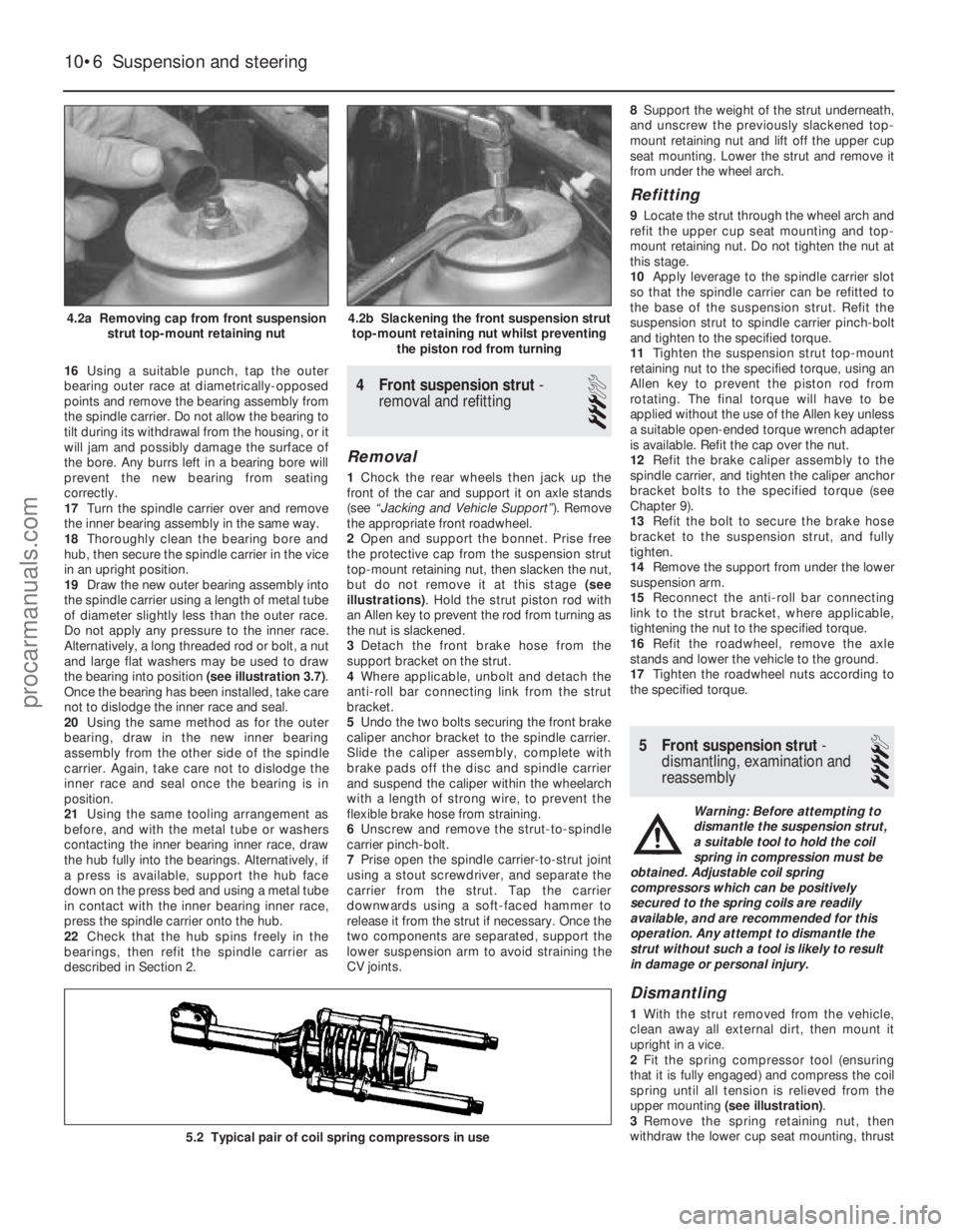
2 Fit the spring compressor tool (ensuring
that it is fully engaged) and compress the coil
spring until all tension is relieved from the
upper mounting (see illustration) .
3 Remove the spring retaining nut, then
withdraw the lower cup seat mounting, thrust
10•6 Suspension and steering
5.2 Typical pair of coil spring compressors in use
4.2b Slackening the front suspension strut
top-mount retaining nut whilst preventing the piston rod from turning4.2a Removing cap from front suspensionstrut top-mount retaining nut
1595Ford Fiesta Remakeprocarmanuals.com
http://vnx.su
Page 201 of 296
8 Front suspension lower arm- removal and refitting
3
Removal
1Chock the rear wheels then jack up the
front of the car and support it on axle stands
(see “Jacking and Vehicle Support” ). Remove
the appropriate front roadwheel.
2 Remove the one-piece undertray (where
fitted), by turning its bayonet-type fasteners.
3 If lower arm mounting brackets are to be
removed on XR2i models, remove the front
suspension crossmember as described in the
previous Section.
4 Unscrew and remove the lower arm
balljoint-to-spindle carrier pinch-bolt. Prise
the joint open using a large flat-bladed tool,
and detach the balljoint from the spindle
carrier. Take care not to damage the balljoint
seal during the separation procedures.
5 Where an anti-roll bar is fitted, undo the two
bolts and remove the clamp bracket.
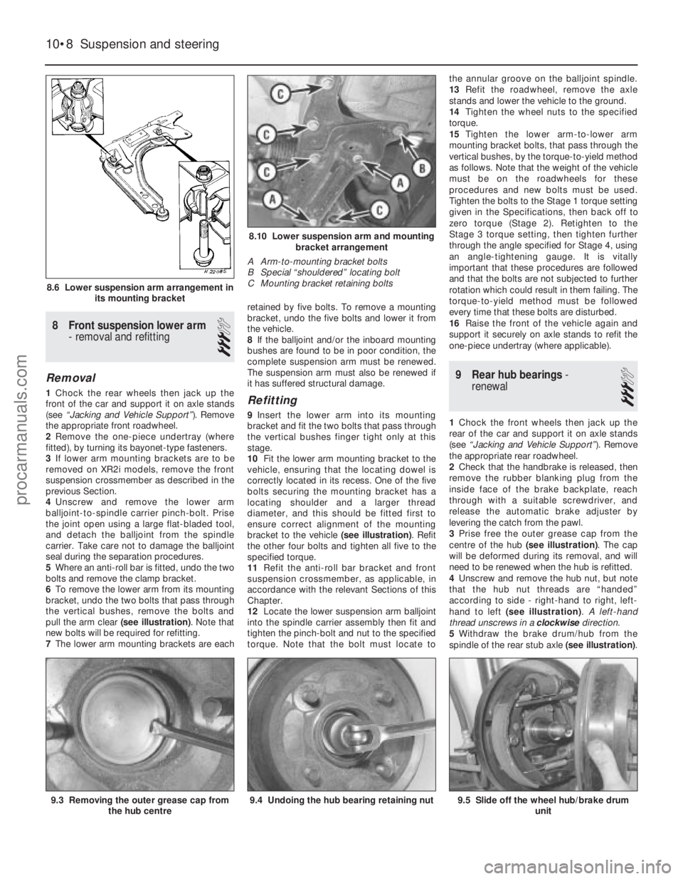
6 To remove the lower arm from its mounting
bracket, undo the two bolts that pass through
the vertical bushes, remove the bolts and
pull the arm clear (see illustration). Note that
new bolts will be required for refitting.
7 The lower arm mounting brackets are each retained by five bolts. To remove a mounting
bracket, undo the five bolts and lower it from
the vehicle.
8
If the balljoint and/or the inboard mounting
bushes are found to be in poor condition, the
complete suspension arm must be renewed.
The suspension arm must also be renewed if
it has suffered structural damage.Refitting
9 Insert the lower arm into its mounting
bracket and fit the two bolts that pass through
the vertical bushes finger tight only at this
stage.
10 Fit the lower arm mounting bracket to the
vehicle, ensuring that the locating dowel is
correctly located in its recess. One of the five
bolts securing the mounting bracket has a
locating shoulder and a larger thread
diameter, and this should be fitted first to
ensure correct alignment of the mounting
bracket to the vehicle (see illustration). Refit
the other four bolts and tighten all five to the
specified torque.
11 Refit the anti-roll bar bracket and front
suspension crossmember, as applicable, in
accordance with the relevant Sections of this
Chapter.
12 Locate the lower suspension arm balljoint
into the spindle carrier assembly then fit and
tighten the pinch-bolt and nut to the specified
torque. Note that the bolt must locate to the annular groove on the balljoint spindle.
13
Refit the roadwheel, remove the axle
stands and lower the vehicle to the ground.
14 Tighten the wheel nuts to the specified
torque.
15 Tighten the lower arm-to-lower arm
mounting bracket bolts, that pass through the
vertical bushes, by the torque-to-yield method
as follows. Note that the weight of the vehicle
must be on the roadwheels for these
procedures and new bolts must be used.
Tighten the bolts to the Stage 1 torque setting
given in the Specifications, then back off to
zero torque (Stage 2). Retighten to the
Stage 3 torque setting, then tighten further
through the angle specified for Stage 4, using
an angle-tightening gauge. It is vitally
important that these procedures are followed
and that the bolts are not subjected to further
rotation which could result in them failing. The
torque-to-yield method must be followed
every time that these bolts are disturbed.
16 Raise the front of the vehicle again and
support it securely on axle stands to refit the
one-piece undertray (where applicable).
9 Rear hub bearings -
renewal
3
1 Chock the front wheels then jack up the
rear of the car and support it on axle stands
(see “Jacking and Vehicle Support” ). Remove
the appropriate rear roadwheel.
2 Check that the handbrake is released, then
remove the rubber blanking plug from the
inside face of the brake backplate, reach
through with a suitable screwdriver, and
release the automatic brake adjuster by
levering the catch from the pawl.
3 Prise free the outer grease cap from the
centre of the hub (see illustration). The cap
will be deformed during its removal, and will
need to be renewed when the hub is refitted.
4 Unscrew and remove the hub nut, but note
that the hub nut threads are “handed”
according to side - right-hand to right, left-
hand to left (see illustration) . A left-hand
thread unscrews in a clockwisedirection.
5 Withdraw the brake drum/hub from the
spindle of the rear stub axle (see illustration).
10•8 Suspension and steering
9.5 Slide off the wheel hub/brake drum
unit9.4 Undoing the hub bearing retaining nut9.3 Removing the outer grease cap fromthe hub centre
8.10 Lower suspension arm and mountingbracket arrangement
A Arm-to-mounting bracket bolts
B Special “shouldered” locating bolt
C Mounting bracket retaining bolts
8.6 Lower suspension arm arrangement in its mounting bracket
1595Ford Fiesta Remakeprocarmanuals.com
http://vnx.su
Page 203 of 296
3Unscrew and remove the upper mounting
through-bolt and nut.
4 Withdraw the upper mounting cup and the
spring seat.
5 The suspension strut and coil spring can now
be separated. If the coil spring or strut is to be
renewed, the original coil spring must be
released from the compressor. If it is to be re-
used, the coil spring can be left in compression.
Examination
6 With the strut assembly now completely
dismantled, examine the mounting
components for wear, damage or deformation.
Renew any of the components as necessary.
7 Examine the strut for signs of fluid leakage.
Check the strut piston for signs of pitting
along its entire length, and check the strut
body for signs of damage or deterioration of
the mountings. Test the operation of the strut,
holding it in an upright position, by moving the
piston through a full stroke, and then through
short strokes of 50 to 100 mm. In both cases,
the resistance felt should be smooth and
continuous. If the resistance is jerky, or
uneven, or if there is any visible sign of wear
or damage to the strut, renewal is necessary.
Reassembly
8 Reassembly is a reversal of the dismantling
procedure but note the following points: a) When the spring is located over the
suspension strut, the spring seat, cup and
through-bolt fitted, tighten the retaining
bolt to the specified torque.
b) When reassembled, check that the upper
and lower spring tails are correctly
engaged with their spring seats before
removing the spring compressor.
12 Rear axle (all models except
Courier) -
removal and refitting
3
Removal
1 Chock the front wheels then jack up the
rear of the car and support it on axle stands
(see “Jacking and Vehicle Support” ). Remove
the rear roadwheels.
2 Refer to Chapter 9 for details, and disconnect
the handbrake cable equaliser from the primary
cable. Remove the handbrake rear cable from
its adjuster and its fixed body locations.
3 Disconnect the rear brake flexible hydraulic
brake hoses from their rigid line connections.
Clamp the hoses before disconnecting them,
to minimise the fluid loss and air entry into the
hydraulic system (see Chapter 9 for details).
4 On ABS-equipped models, undo the
retaining nuts and detach the ABS load-
apportioning valve operating links from the
axle beam. Do not remove the load-
apportioning valve (see Chapter 9).
5 Locate suitable jacks or axle stands under
the axle beam to support its weight (not to lift
it), then unscrew the four mounting bracket
bolts each side. 6
Unscrew and remove the strut-to-axle
mounting bolt each side.
7 Check that all associated fittings are clear,
then lower the axle and remove it from under
the vehicle.
8 If the twist beam axle has been damaged, it
must be renewed. Refer to Chapter 9 for
details on removing the rear brakes from the
axle. To remove the front mounting/pivot
brackets from the axle, unscrew the pivot bolt.
Refitting
9 Refitting is a reversal of the removal
procedure, but note the following: a) Reconnect the axle at the front floor mountings first, and tighten the retaining
bolts to the specified torque.
b) Reconnect the axle to the suspension struts, but do not fully retighten the securing
bolts until after the vehicle is lowered to the
ground and is standing on its wheels.
c) Ensure that all brake fluid line connections are clean before reconnecting them. Refer
to the appropriate Sections in Chapter 9
for specific details on reconnecting the
brake lines, bleeding the brake hydraulic
system, and for reconnecting the
handbrake cable and its adjustment.
d) When the vehicle is lowered and is standing
on its wheels, tighten the suspension
fastenings to their specified torque settings.
13 Rear axle pivot bushes (all
models except Courier) -
renewal
3
Note: Two different types of pivot bushes
have been fitted during the course of Fiesta
production. It is understood that once stocks
of the early type are exhausted, only the latter
type will be supplied by Ford parts dealers. If
renewing pivot bushes on a pre-April 1990
model, and only the later type bushes are
available, fit the new bushes as described
from paragraph 15 onward.
Pre-April 1990 models
1 Chock the front wheels then jack up the
rear of the car and support it on axle stands
(see “Jacking and Vehicle Support” ).2
Position a suitable support (preferably
adjustable) under the axle twist beam so that
it is capable of carrying the weight of the axle
(not the weight of the vehicle).
3 On ABS-equipped models, undo the
retaining nuts and detach the ABS load-
apportioning valve operating links from the
axle beam. Do not remove the load-
apportioning valve (see Chapter 9).
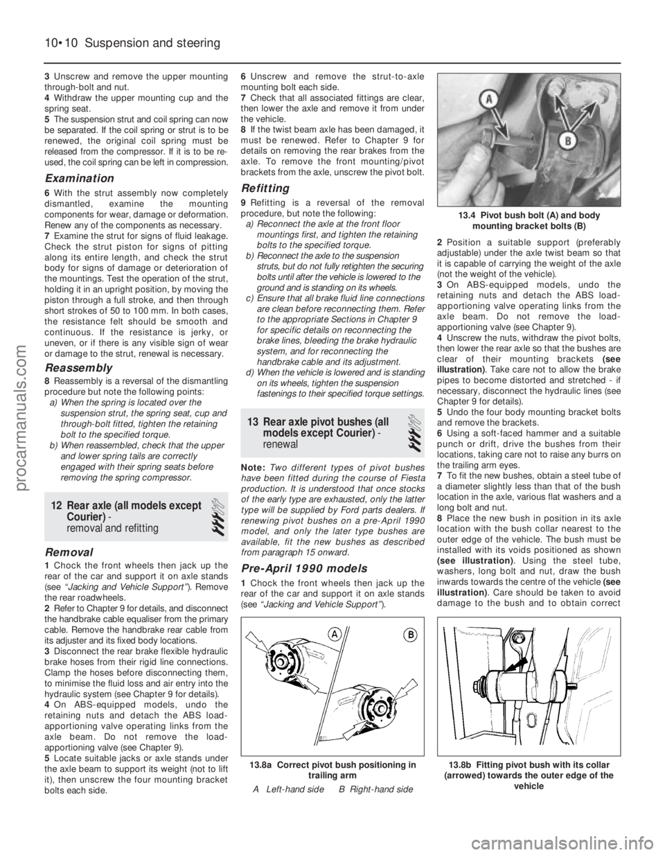
4 Unscrew the nuts, withdraw the pivot bolts,
then lower the rear axle so that the bushes are
clear of their mounting brackets (see
illustration) . Take care not to allow the brake
pipes to become distorted and stretched - if
necessary, disconnect the hydraulic lines (see
Chapter 9 for details).
5 Undo the four body mounting bracket bolts
and remove the brackets.
6 Using a soft-faced hammer and a suitable
punch or drift, drive the bushes from their
locations, taking care not to raise any burrs on
the trailing arm eyes.
7 To fit the new bushes, obtain a steel tube of
a diameter slightly less than that of the bush
location in the axle, various flat washers and a
long bolt and nut.
8 Place the new bush in position in its axle
location with the bush collar nearest to the
outer edge of the vehicle. The bush must be
installed with its voids positioned as shown
(see illustration) . Using the steel tube,
washers, long bolt and nut, draw the bush
inwards towards the centre of the vehicle (see
illustration) . Care should be taken to avoid
damage to the bush and to obtain correct
10•10 Suspension and steering
13.8b Fitting pivot bush with its collar
(arrowed) towards the outer edge of the vehicle13.8a Correct pivot bush positioning intrailing arm
A Left-hand side B Right-hand side
13.4 Pivot bush bolt (A) and body mounting bracket bolts (B)
1595Ford Fiesta Remakeprocarmanuals.com
http://vnx.su
Page 205 of 296
mountings for signs of wear. Test the
operation of the unit, holding it in an upright
position, by moving the piston through a full
stroke, and then through short strokes of 50
to 100 mm. In both cases, the resistance felt
should be smooth and continuous. If the
resistance is jerky, or uneven, or if there is any
visible sign of wear or damage, the shock
absorber should be renewed. Note that if
either unit is to be renewed, it is good practice
to renew both together as a matched pair.
Refitting
4Locate the unit in position and refit the
mounting bolts and nut. Do not fully tighten
the mountings at this stage.
5 Lower the vehicle to the ground and rock it
to settle the suspension. Raise the vehicle
again, as necessary, until the shock absorber
is at an angle of 50° ± 5° to the horizontal.
With the shock absorber in this position,
tighten the upper and lower mountings to the
specified torque.
17 Rear suspension assembly (Courier models) -
removal and refitting
3
Removal
1 Chock the front wheels then jack up the
rear of the car and support it on axle stands
(see “Jacking and Vehicle Support” ). Remove
the rear roadwheels.
2 Refer to Chapter 9 for details, and
disconnect the handbrake cable equaliser
from the primary cable. Remove the
handbrake rear cable from its adjuster and its
fixed body locations. Release the exhaust
system mountings as necessary to allow the
handbrake cable to be withdrawn over the
rear of the exhaust.
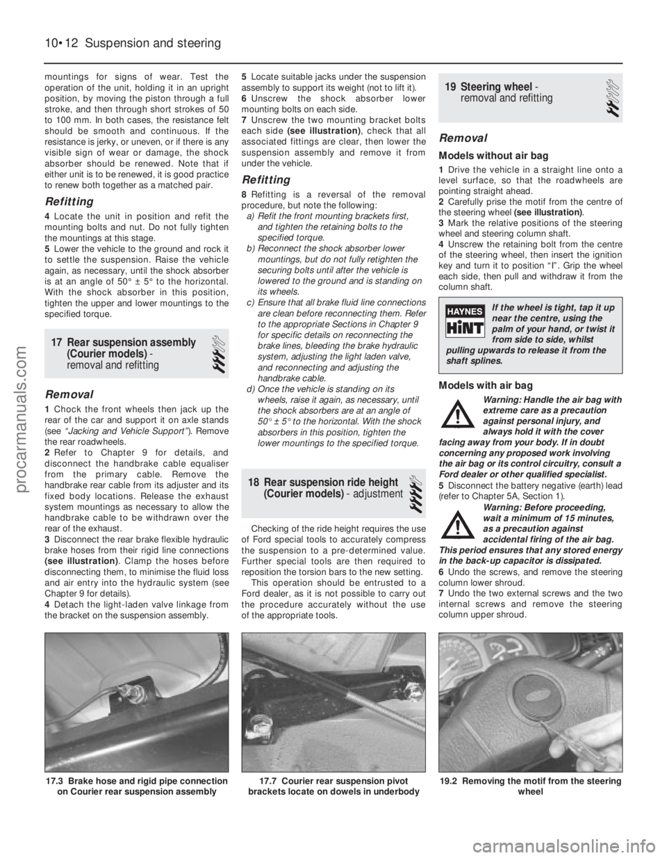
3 Disconnect the rear brake flexible hydraulic
brake hoses from their rigid line connections
(see illustration) . Clamp the hoses before
disconnecting them, to minimise the fluid loss
and air entry into the hydraulic system (see
Chapter 9 for details).
4 Detach the light-laden valve linkage from
the bracket on the suspension assembly. 5
Locate suitable jacks under the suspension
assembly to support its weight (not to lift it).
6 Unscrew the shock absorber lower
mounting bolts on each side.
7 Unscrew the two mounting bracket bolts
each side (see illustration) , check that all
associated fittings are clear, then lower the
suspension assembly and remove it from
under the vehicle.
Refitting
8 Refitting is a reversal of the removal
procedure, but note the following: a) Refit the front mounting brackets first,
and tighten the retaining bolts to the
specified torque.
b) Reconnect the shock absorber lower
mountings, but do not fully retighten the
securing bolts until after the vehicle is
lowered to the ground and is standing on
its wheels.
c) Ensure that all brake fluid line connections are clean before reconnecting them. Refer
to the appropriate Sections in Chapter 9
for specific details on reconnecting the
brake lines, bleeding the brake hydraulic
system, adjusting the light laden valve,
and reconnecting and adjusting the
handbrake cable.
d) Once the vehicle is standing on its
wheels, raise it again, as necessary, until
the shock absorbers are at an angle of
50° ± 5° to the horizontal. With the shock
absorbers in this position, tighten the
lower mountings to the specified torque.
18 Rear suspension ride height (Courier models) - adjustment
4
Checking of the ride height requires the use
of Ford special tools to accurately compress
the suspension to a pre-determined value.
Further special tools are then required to
reposition the torsion bars to the new setting.
This operation should be entrusted to a
Ford dealer, as it is not possible to carry out
the procedure accurately without the use
of the appropriate tools.
19 Steering wheel -
removal and refitting
2
Removal
Models without air bag
1 Drive the vehicle in a straight line onto a
level surface, so that the roadwheels are
pointing straight ahead.
2 Carefully prise the motif from the centre of
the steering wheel (see illustration).
3 Mark the relative positions of the steering
wheel and steering column shaft.
4 Unscrew the retaining bolt from the centre
of the steering wheel, then insert the ignition
key and turn it to position “I”. Grip the wheel
each side, then pull and withdraw it from the
column shaft.
Models with air bag
Warning: Handle the air bag with
extreme care as a precaution
against personal injury, and
always hold it with the cover
facing away from your body. If in doubt
concerning any proposed work involving
the air bag or its control circuitry, consult a
Ford dealer or other qualified specialist.
5 Disconnect the battery negative (earth) lead
(refer to Chapter 5A, Section 1).
Warning: Before proceeding,
wait a minimum of 15 minutes,
as a precaution against
accidental firing of the air bag.
This period ensures that any stored energy
in the back-up capacitor is dissipated.
6 Undo the screws, and remove the steering
column lower shroud.
7 Undo the two external screws and the two
internal screws and remove the steering
column upper shroud.
10•12 Suspension and steering
19.2 Removing the motif from the steering wheel17.7 Courier rear suspension pivot
brackets locate on dowels in underbody17.3 Brake hose and rigid pipe connection on Courier rear suspension assembly
1595Ford Fiesta Remake
If the wheel is tight, tap it up
near the centre, using the
palm of your hand, or twist it
from side to side, whilst
pulling upwards to release it from the
shaft splines.
procarmanuals.com
http://vnx.su
Page 211 of 296
Front wheel toe setting -
checking and adjustment
2Due to the special measuring equipment
necessary to accurately check the wheel
alignment, and the skill required to use it
properly, checking and adjustment is best left
to a Ford dealer or similar expert. Note that
most tyre-fitting shops now possess
sophisticated checking equipment. The
following is provided as a guide, should the
owner decide to carry out a DIY check.
3 The front wheel toe setting is checked by
measuring the distance between the front and
rear inside edges of the roadwheel rims.
Proprietary toe measurement gauges are
available from motor accessory shops.
Adjustment is made by screwing the track
rods in or out of their track rod end balljoints,
to alter the effective length of the track rod
assemblies.
4 For accurate checking, the vehicle must
be at the kerb weight, ie unladen and with a
full tank of fuel.
5 Before starting work, check the tyre
pressures and tread wear, the condition of the
hub bearings, the steering wheel free play,
and the condition of the front suspension
components (see Chapter 1). Correct any
faults found.
6 Park the vehicle on level ground, check that
the front roadwheels are in the straight-ahead
position, then rock the rear and front ends to settle the suspension. Release the handbrake,
and roll the vehicle backwards 1 metre, then
forwards again, to relieve any stresses in the
steering and suspension components.
7
Measure the distance between the front
edges of the wheel rims and the rear edges of
the rims. Subtract the smallest measurement
from the largest, and check that the result is
within the specified range.
8 If adjustment is necessary, apply the
handbrake, then jack up the front of the
vehicle and support it securely on axle stands
(see “Jacking and Vehicle Support” ). Turn the
steering wheel onto full-left lock, and record
the number of exposed threads on the right-
hand track rod. Now turn the steering onto
full-right lock, and record the number of
threads on the left-hand side. If there are the
same number of threads visible on both sides,
then subsequent adjustment should be made
equally on both sides. If there are more
threads visible on one side than the other, it
will be necessary to compensate for this
during adjustment. Note:It is most important
that after adjustment, the same number of
threads are visible on each track rod.
9 First clean the track rod end; if they are
corroded, apply penetrating fluid before
starting adjustment. Release the rubber gaiter
outboard clips (where necessary), and peel
back the gaiter; apply a smear of grease to
the inside of the gaiter, so that both are free, and will not be twisted or strained as their
respective track rods are rotated.
10
Use a straight-edge and a scriber or
similar to mark the relationship of each track
rod to its track rod end balljoint, then, holding
each track rod in turn, unscrew its locknut
fully.
11 Alter the length of the track rods, bearing
in mind the note made in paragraph 8. Screw
them into or out of the track rod end balljoints,
rotating the track rods using a self-grip
wrench. Shortening the track rods (screwing
them into their track rod end balljoints) will
reduce toe-in/increase toe-out.
12 When the setting is correct, hold the track
rods and securely tighten the track rod end
balljoint locknuts. Count the exposed threads
to check the length of both track rods. If they
are not the same, then the adjustment has not
been made equally, and problems will be
encountered with tyre scrubbing in turns;
also, the steering wheel spokes will no longer
be horizontal when the wheels are in the
straight-ahead position.
13 If the track rod lengths are the same, lower
the vehicle to the ground and re-check the
toe setting; re-adjust if necessary. When the
setting is correct, securely tighten the track rod
end balljoint locknuts. Ensure that the rubber
gaiters are seated correctly, and are not
twisted or strained, and secure them in position
with new retaining clips (where necessary).
10•18 Suspension and steering
1595Ford Fiesta Remakeprocarmanuals.com
http://vnx.su
Page 267 of 296

1595 Ford Fiesta Remake
REF
Dimensions and weights
Note:All figures are approximate, and may vary according to model. Refer to m\
anufacturer’s data for exact figures.
Dimensions
Overall length: 3/5 door hatchback models . . . . . . . . . . . . . . . . . . . . . . . . . . . . . . . . 3743 mm
XR2i, RS Turbo and RS 1800 models . . . . . . . . . . . . . . . . . . . . . . . . . 3801 mm
Courier models . . . . . . . . . . . . . . . . . . . . . . . . . . . . . . . . . . . .\
. . . . . . 4052 mm
Width (excluding mirrors): 3/5 door hatchback models . . . . . . . . . . . . . . . . . . . . . . . . . . . . . . . . 1606 mm
XR2i, RS Turbo and RS 1800 models . . . . . . . . . . . . . . . . . . . . . . . . . 1630 mm
Courier models . . . . . . . . . . . . . . . . . . . . . . . . . . . . . . . . . . . .\
. . . . . . 1650 mm
Overall height: 3/5 door hatchback models . . . . . . . . . . . . . . . . . . . . . . . . . . . . . . . . 1376 mm
XR2i, RS Turbo and RS 1800 models . . . . . . . . . . . . . . . . . . . . . . . . . 1365 mm
Courier models . . . . . . . . . . . . . . . . . . . . . . . . . . . . . . . . . . . .\
. . . . . . 1812 mm
Wheelbase: Courier models . . . . . . . . . . . . . . . . . . . . . . . . . . . . . . . . . . . .\
. . . . . . 2700 mm
All other models . . . . . . . . . . . . . . . . . . . . . . . . . . . . . . . . . . . .\
. . . . . 2446 mm
Front track: 3/5 door hatchback models . . . . . . . . . . . . . . . . . . . . . . . . . . . . . . . . 1392 mm
XR2i, RS Turbo and RS 1800 models . . . . . . . . . . . . . . . . . . . . . . . . . 1406 mm
Courier models . . . . . . . . . . . . . . . . . . . . . . . . . . . . . . . . . . . .\
. . . . . . 1392 mm
Rear track: 3/5 door hatchback models . . . . . . . . . . . . . . . . . . . . . . . . . . . . . . . . 1384 mm
XR2i, RS Turbo and RS 1800 models . . . . . . . . . . . . . . . . . . . . . . . . . 1376 mm
Courier models . . . . . . . . . . . . . . . . . . . . . . . . . . . . . . . . . . . .\
. . . . . . 1395 mm
Dimensions and weights . . . . . . . . . . . . . . . . REF•1
Vehicle identification . . . . . . . . . . . . . . . . . . . REF•3
General repair procedures . . . . . . . . . . . . . . REF•4
Jacking and vehicle support . . . . . . . . . . . . . REF•5
Buying spare parts . . . . . . . . . . . . . . . . . . . . REF•5
Radio/cassette unit anti-theft system . . . . . REF•5Conversion factors . . . . . . . . . . . . . . . . . . . .
REF•6
Tools and working facilities . . . . . . . . . . . . . . REF•7
MOT test checks . . . . . . . . . . . . . . . . . . . . . REF•10
Fault finding . . . . . . . . . . . . . . . . . . . . . . . . REF•14
Glossary of technical terms . . . . . . . . . . . . REF•22
Index . . . . . . . . . . . . . . . . . . . . . . . . . . . . . . REF•27
Reference REF•1
procarmanuals.com
http://vnx.su
Page 268 of 296

1595 Ford Fiesta Remake
REF•2Conversion factors
Weights
Kerb weight*:3-door hatchback:1.0 litre models . . . . . . . . . . . . . . . . . . . . . . . . . . . . . . . . . . . .\
. . . . 770 to 780 kg
1.1 litre models . . . . . . . . . . . . . . . . . . . . . . . . . . . . . . . . . . . .\
. . . . 785 to 850 kg
1.3 litre models . . . . . . . . . . . . . . . . . . . . . . . . . . . . . . . . . . . .\
. . . . 825 to 870 kg
1.4 litre models . . . . . . . . . . . . . . . . . . . . . . . . . . . . . . . . . . . .\
. . . . 920 to 940 kg
1.6 litre models . . . . . . . . . . . . . . . . . . . . . . . . . . . . . . . . . . . .\
. . . . 990 to 1010 kg
XR2i (1.6 litre) models . . . . . . . . . . . . . . . . . . . . . . . . . . . . . . . . . . . 890 to 910 kg
XR2i (1.8 litre) models . . . . . . . . . . . . . . . . . . . . . . . . . . . . . . . . . . . 955 to 974 kg
RS Turbo models . . . . . . . . . . . . . . . . . . . . . . . . . . . . . . . . . . . .\
. . 910 to 930 kg
RS 1800 models . . . . . . . . . . . . . . . . . . . . . . . . . . . . . . . . . . . .\
. . . 954 to 965 kg
5-door hatchback: 1.0 litre models . . . . . . . . . . . . . . . . . . . . . . . . . . . . . . . . . . . .\
. . . . 795 to 810 kg
1.1 litre models . . . . . . . . . . . . . . . . . . . . . . . . . . . . . . . . . . . .\
. . . . 810 to 845 kg
1.3 litre models . . . . . . . . . . . . . . . . . . . . . . . . . . . . . . . . . . . .\
. . . . 845 to 870 kg
1.4 litre models . . . . . . . . . . . . . . . . . . . . . . . . . . . . . . . . . . . .\
. . . . 840 to 870 kg
1.6 litre models . . . . . . . . . . . . . . . . . . . . . . . . . . . . . . . . . . . .\
. . . . 980 to 1029 kg
Vans: 1.0 litre models . . . . . . . . . . . . . . . . . . . . . . . . . . . . . . . . . . . .\
. . . . 775 kg
1.1 litre models . . . . . . . . . . . . . . . . . . . . . . . . . . . . . . . . . . . .\
. . . . 775 to 790 kg
1.3 litre models . . . . . . . . . . . . . . . . . . . . . . . . . . . . . . . . . . . .\
. . . . 795 kg
Courier models . . . . . . . . . . . . . . . . . . . . . . . . . . . . . . . . . . . .\
. . . . 920 kg
Payload: 1.0 litre Van models . . . . . . . . . . . . . . . . . . . . . . . . . . . . . . . . . . . .\
310 to 335 kg
1.1 litre Van models . . . . . . . . . . . . . . . . . . . . . . . . . . . . . . . . . . . .\
310 to 335 kg1.3 litre Van models . . . . . . . . . . . . . . . . . . . . . . . . . . . . . . . . . . . .\
330 kgCourier models . . . . . . . . . . . . . . . . . . . . . . . . . . . . . . . . . . . .\
. . . . 515 to 525 kg
Maximum roof rack load . . . . . . . . . . . . . . . . . . . . . . . . . . . . . . . . . . . 75 kg
Maximum towing weight . . . . . . . . . . . . . . . . . . . . . . . . . . . . . . . . . . . Refer to your Ford dealer for weights and legal requirements concerning anticipated gradients and altitudes.
*Exact kerb weight varies depending on model - refer to VIN plate for de\
tails
procarmanuals.com
http://vnx.su