1988 PONTIAC FIERO warning
[x] Cancel search: warningPage 1614 of 1825
INSTRUMENT PANEL. GAGES & CONSOLE 8C-3
tank only when ignition switch is turned to "ON" or
"ACCESSORY" positions.
When ignition is turned to "OFF" or "START"
positions, the pointer may come to rest at any position.
The letters
"E" and "F" on the fuel gage are used to
point out direction of indicator travel only.
TEMPERATURE WARNING LIGHT
The engine temperature warning light is
controlled by a thermal switch which senses engine
coolant temperatures.
When the ignition switch is turned to "START"
position, a test circuit is closed and the light will come
on to indicate whether the light is functioning properly.
It is important to note that with low boiling-point
coolants (such as plain water) the temperature light
may not come on even though the coolant is boiling.
GENERATOR WARNING LIGHT
The generator warning light, located in the
instrument cluster, should come on when the ignition
switch is turned
"ON" and engine is not running. If
not, either the bulb is burned out or wiring to generator
has an open circuit.
When the generator voltage output becomes
greater than the battery voltage, the
"GEN" light
should go out. This does not, however, indicate
whether the battery is being charged or if the voltage
regulator is functioning properly.
Checks of the charging system are covered in
Section 6D, 'Engine Electrical'.
ENGINE OIL PRESSURE LIGHT
The engine oil pressure warning light is mounted
in the instrument cluster and controlled by a pressure
operated switch located on the engine block. When the ignition switch is
in the
"run" or "start9' position, the
oil pressure light should come on. If not, the bulb is
burned out, there is an open circuit between the bulb
and the oil pressure switch, or there is an open circuit
between the oil pressure switch and the choke heater.
After the engine is running, the oil pressure light
should go out when the oil pressure reaches the correct
specification. If not an oil pressure problem, a faulty oil
pressure switch or an open circuit from the choke
heater fuse to the oil pressure switch is indicated.
"SERVICE ENGINE SOON" LIGHT
All cars have a "SERVICE ENGINE SOON"
light mounted in the instrument cluster. The
"SERVICE ENGINE SOON9' light should come on
during engine starting. The light may stay on
a short
time after the engine starts.
If the light comes on while
driving, service to the emission control system may be
required. See Section
6E and Section 8A-80,
'Instrument Cluster', for complete diagnosis and
wiring diagrams of the
""P;RVICE ENGINE SOON"
light circuit.
UPSHIFT INDICATOR LIGHT
If your vehicle has a manual transmission, there
may be an
''Upshift" light on the instrument panel.
This light is illuminated to indicate optimum shift
points throughout the range from optimum fuel
economy to optimum performance. When this light is
on, shift your transmission to the next higher gear
range if conditions permit. For fuel economy,
accelerate slowly and shift when the light goes on. For
performance, accelerate as desired and shift when the
light goes on.
Safe operation of the vehicle may require shifting
differently than indicated by the "Upshift" light to
adapt to weather, road or traffic conditions.
Downshifting one or more gears may be required
to keep the engine running smoothly or to maintain
satisfactory performance.
DIAGNOSIS
Diagnostic information for all instrument panel
electrical systems is found in Section
8A-80,
'Instrument Panel'.
CAUTION: When removing or
installing any electrical units,
disconnect the negative battery cable
to prevent possible short circuits
which could lead to personal injury
and/or property damage. When
replacing a speedometer or
odometer assembly, the law requires the
odometer reading of the replacement unit to
be set to register the same mileage as the
prior odometer.
if the same mileage cannot be
set, the
law requires that the replacement
odometer be set to zero and a label be
installed on the driver's door frame to show
the previous odometer reading and the date
of replacement.
GENERAL BNFORMATlOM
INSTRUMENT PANEL AND GAGES
The instrument panel is a single unit design and
and screws. To service the instrument panel and
all parts attach to the main instrument panel with clips components see Figs. 601 through 610.
Page 1674 of 1825
MISCELLANEOUS ACCESSORIES 96-4
SCELLANEOUS ACCESSOR
General Description ................................. 9G-1
Rally Gages .................................................. 9G- 1
Tachometer ................................................. 9G- 1
Trip Odometer
............................................. 9G- 1
Electric Rear Window Defogger ................. 9G-2
Power Remote Control Rearview
Mirror ........................................................ 9G-2
Diagnosis .................................................... 9G-2
Rally Gages ............................................... 9G-2
Tachometer .................................... .... .... 9G-2
Electric Rear Window Defogger ................. 9G-2
Power Remote Control Rearview
Mirror ........................................................ 96-2
Dash and Console Mounted
Accessory Switches
................................. 9G-4
General Description .................................. 9G-4
Electronic Glare Control Mirror ................. 9G-4
On-Car Service ............................................. 9G-4
Rally Gages, Tach ....................................... 96-4.
Rear Window Defogger ............................ 96-4.
Power Remote Control Mirror .................... 9G-4
GENERAL BESCRIP"T0N
RALLY GAGES
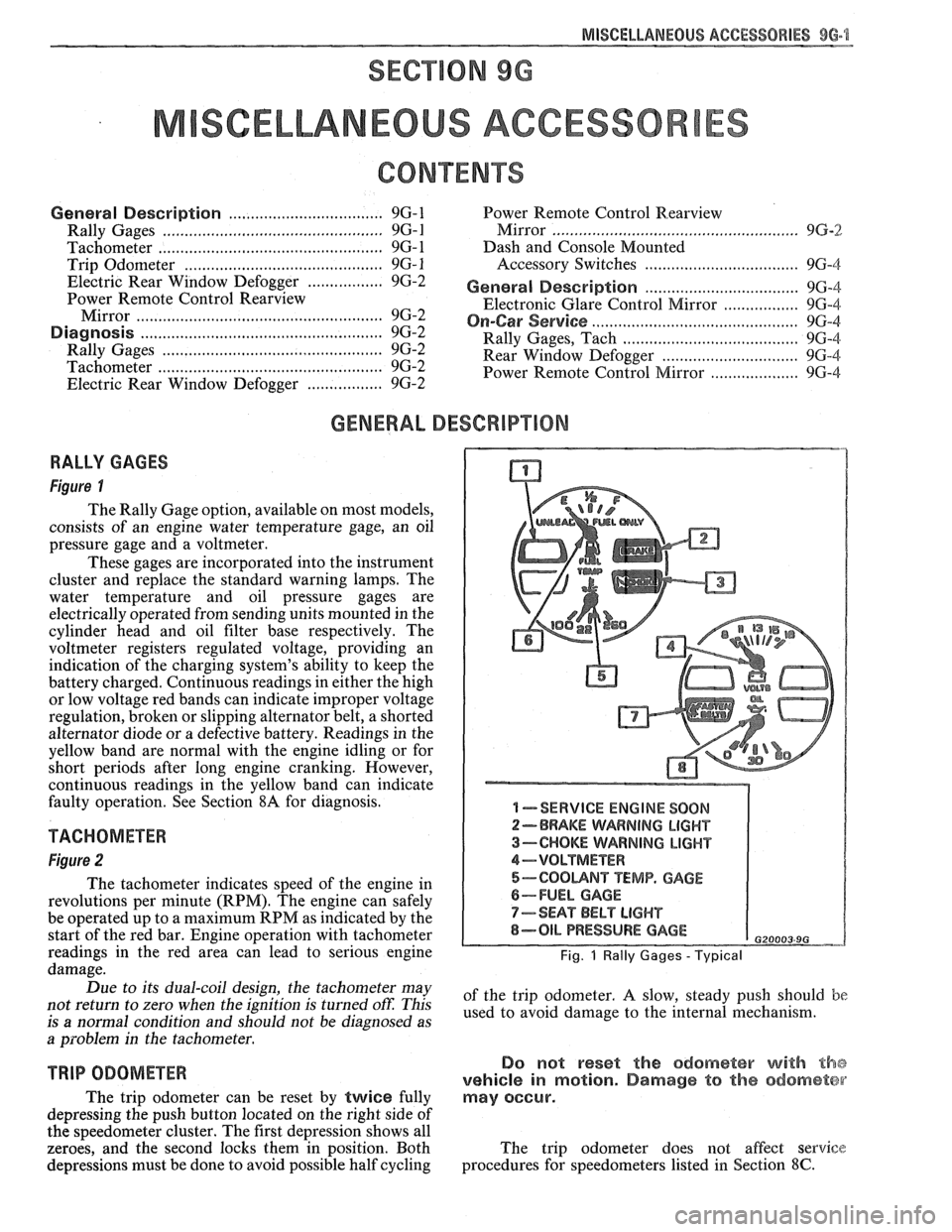
Figure I
The Rally Gage option, available on most models,
consists of an engine water temperature gage, an oil
pressure gage and a voltmeter.
These gages are incorporated into the instrument
cluster and replace the standard warning lamps. The
water temperature and oil pressure gages are
electrically operated from sending units mounted in the
cylinder head and oil filter base respectively. The
voltmeter registers regulated voltage, providing an
indication of the charging system's ability to keep the
battery charged. Continuous readings in either the high
or low voltage red bands can indicate improper voltage
regulation, broken or slipping alternator belt,
a shorted
alternator diode
or a defective battery. Readings in the
yellow band are normal with the engine idling or for
short periods after long engine cranking. However,
continuous readings in the yellow band can indicate
faulty operation. See Section
8A for diagnosis.
TACHOMETER
Figure 2
The tachometer indicates speed of the engine in
revolutions per minute (RPM). The engine can safely
be operated up to a maximum RPM as indicated by the
start of the red bar. Engine operation with tachometer
readings in the red area can lead to serious engine
damage.
Due to its dual-coil design, the tachometer may
not return to zero when the ignition
is turned oft: This
is
a normal condition and should not be diagnosed as
a problem in the tachometer.
TRIP ODOMETER
The trip odometer can be reset by twice fully
depressing the push button located on the right side of
the speedometer cluster. The first depression shows all
zeroes, and the second locks them in position. Both
depressions must be done to avoid possible half cycling
I -SERVICE ENGINE SOON
2-BRAKE WARNING LIGHT
3-CHOKE WARNING LIGHT
4-VOLTMETER
5-COOUNT TEMP. GAGE
6-FUEL GAGE
7-SEAT BELT LIGHT
8-OIL PRESSURE GAGE G20003 9G
Fig. 1 Rally Gages - Typical
of the trip odometer. A slow, steady push should be
used to avoid damage to the internal mechanism.
Do not reset the odometer with the
vehicle in motion. Damage to the odometer
may occur.
The trip odometer does not affect service
procedures for speedometers listed in Section
8C.
Page 1693 of 1825
1 H-12 GENERAL INFORMATION - F STYLE
with additional adhesive in sufficient
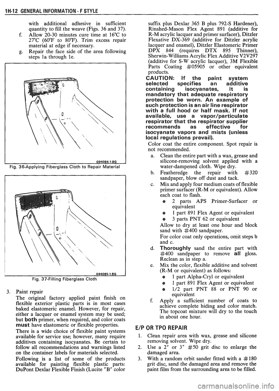
quantity to fill the weave (Figs. 36 and 37).
f. Allow
20-30 minutes cure time at 16°C to
27°C (60°F to 80°F). Trim excess repair
material at edge if necessary.
g. Repair
the face side of the area following
steps la through le.
Fig. 36-Applying Fiberglass Cloth to Repair Material
Fig. 37-Filling Fiberglass Cloth
3. Paint repair
The original factory applied paint finish on
flexible exterior plastic parts is in most cases
baked elastomeric enamel. However, for repair, either a lacquer or enamel system may be used;
but
both primer, when required, and color coats
must have elastomeric or flexible properties.
There is a wide choice of flexible paint systems
available for service use; however, many require
additives containing isocyanates. Be certain to
follow all recommendations and warnings listed
on the container labels for materials selected.
Following is a list of some of the products
available for painting flexible plastic parts:
DuPont Dexlar Flexible Finish (Lucite " B" color suffix
plus Dexlar 365 B plus 792-S Hardener),
Rinshed-Mason Flex Agent 891 (additive for
R-M acrylic lacquer and primer surfacer), Ditzler
Flexative DX-369 (additive for Ditzler acrylic
lacquer and enamel), Ditzler Elastomeric Primer
DPX 844 (requires DTX 895 Thinner),
Sherwin-Williams Acrylic Flex Additive
V2V297
(additive for S-W acrylic lacquer), 3M Flexible
Parts Coating
kt05905 or other equivalent
products.
CAUTION: If the paint system
selected specifies an additive
containing isocyanates, it is
mandatory that adequate respiratory
protection be worn. An example of
such protection is an air line respirator
with a full hood or half mask.
If not
available, use a
vapor/particulate
respirator that the respirator supplier
recommends as effective for
isocyanate vapors and mists (unless
local regulations prevail).
Color coat the entire component. Spot repair is
not recommended.
a. Clean the entire part with a wax, grease and
silicone-removing solvent applied with a
water-dampened cloth. Wipe dry.
b. Featheredge the repair with
#320
sandpaper, blow off dust and tack.
c. Mix and apply four medium coats of flexible
primer surfacer (R-M or equivalent). Allow
each coat to flash.
o 2 parts APS Primer-Surfacer or
equivalent
s 1 part 891 Flex Agent or equivalent
o 3 parts PNT 62 or equivalent
Allow to dry at least one hour and block
sand with
#400 sandpaper.
For color coat only operations, omit steps
b
and c.
d.
Thoroughly sand the entire part with
#400 sandpaper to remove all gloss.
Reclean as in step a.
e. Mix the color, flexible additive and solvent
(R-M or equivalent) as follows:
e 1 part Alpha-Cry1 or equivalent
e 1 part 891 Flex Agent or equivalent
o 1/2 part PNT 88 or PNT 90 or
equivalent
f. Apply a sufficient number of coats to
achieve complete hiding and color match.
The topcoat mixture will dry to the touch
in about one hour.
E/P OR TPO REPAIR
1. Clean repair area with wax, grease and silicone
removing solvent. Wipe dry.
2. Use
a 2" or 3" #50 grit disc to enlarge the
damaged area.
3. With a random
orbit sander fitted with a
# 180
grit disc, sand the damaged area and remove
the
paint film from the surrounding area to be filled.
Page 1706 of 1825
UNDERBODY-F STYLE 3H-1
SECTION 3H
UNDERBODY
CONTENTS
General Body Construction .......................................................................................................... 3H- 1
Alignment Checking ................................................................................................................ 3H- I
Floor Pan Insulators ...................... .. ........................................................................................ 3H- 1
Floor Carpets ................................................................................................................................. 3H-2
metric-to-English dimensional conversion data.
Dimensions to gage holes are measured to dead center
GENERAL BODY CONSTRUCTION of the holes and flush to adjacent surface metal unless
Information in this section pertains to unitized otherwise specified.
body construction which
incorporates integral front
and rear frame side rails. FLOOR PAN INSULATORS
Consideration must be given when checking
underbody dimensions. The engine front suspension
lower control arms are supported by a cross member.
The cross member, in turn, is bolted to the body at six
locations
-- three on each side of the engine front
compartment lower rails. Mounting provisions for the
front suspension system are shared by chassis
components (suspension lower control arms and cross
member) and body components (engine compartment
side panels). The suspension strut towers must be
dimensionally correct in relation to the remainder of
the underbody in order to maintain specified
suspension strut and
castedcamber angles.
Since the individual underbody components also
contribute directly to the overall strength of the body,
it is essential that proper welding techniques be
observed during service repair operations. The
underbody components should be properly sealed and
rustproofed whenever body repair operations destroy
or damage the original sealing and rustproofing. When
rustproofing critical underbody components, it is
essential that a good quality type of air dry primer be
used (such as corrosion resistant chromate or
equivalent material). It is not advisable to use
combination type primer-surfacers.
ALIGNMENT CHECKING
An accurate method of determining the
alignment of the underbody utilizes a measuring tram
gage. The tram gage set required to perform the
recommended measuring checks must include a
vertical pointer capable of reaching 914 mm (36").
Two types of measurements can be made with
a
tram gage: direct point-to-point measurements and
measurements calculated on a horizontal
vlane (datum
line) parallel to the underbody. In the
latter case, the
vertical pointers must be set as specified for each point
to be measured (Fig. 3-1).
Point-to-point measurements are generally taken
only on engine compartment components (Fig. 3-2)
and simply require the vertical pointers to be equally
set.
Figure #3-3 describes the alphabetically
identified points of measurement. Figure 3-4 provides Floor
pan insulators have been designed for the
higher floor pan temperatures that result from the use
of the catalytic converter in the exhaust system.
Therefore, when servicing a vehicle in the field, it is
essential that any insulators that may have been
disturbed or removed be reinstalled in the original
sequence and location. Also, if it becomes necessary to
replace an insulator, the material specified for that
particular location on the floor pan must be used. The
types of materials are listed below. Items 1 and
2 are
rolled stock and are ordered by linear foot and cut to
fit.
1. Insulator floor pan
(cerra blanket thermal) -
consists of 10 mm (3/8") thick aluminum silica
(type 1).
2. Insulator floor pan (amberlite) - consists of 10
mm
(3/8") thick resinated fibers (type 2).
3. Insulator floor pan sheet (phenolic bonded fiber
glass)
305 mm x 457 mm (12" x 18") cut to size,
(type 3).
All of the above materials must meet
Motor Vehicle Safety Standard No. 302 for
flammability.
When servicing or replacing interior insulators,
the following instructions must be observed:
1. Insulators must be installed in the original
position and sequence. Pieces should be butted
together in order to avoid gapping or
overlapping.
2. If it is necessary to replace an insulator, the
specified material must be used.
3. Use original
part to determine the amount of
replacement material required and as a template
for cutting and fitting the new piece to the floor
pan.
4. When installing insulator, do not enlarge cutouts
or holes that are used for the attachment of
interior components such as seats or seat belts.
5. Cross body harnesses for interior components
such as power seats, lap belt warning light and
buzzer or rear speakers must be routed over the
floor pan insulators in the original location and
clipped in place.
Page 1812 of 1825
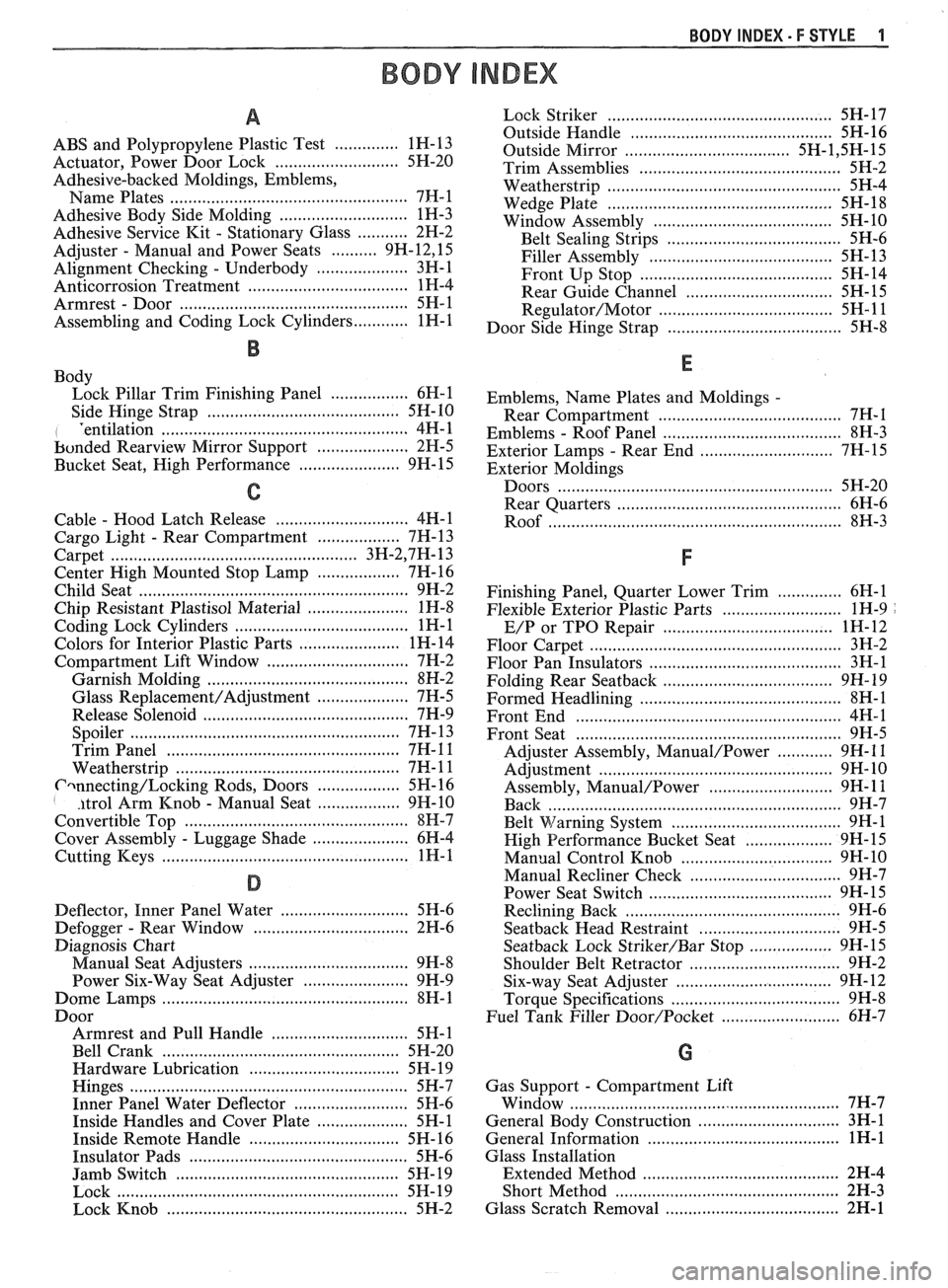
BODY INDEX . F STYLE 1
BODY INDEX
a
ABS and Polypropylene Plastic Test .............. 1 H- 13
Actuator. Power Door Lock
.......................... 5H-20
Adhesive-backed Moldings. Emblems. Name Plates
.................................................... 7FI-1
Adhesive Body Side Molding ............................ 1H-3
Adhesive Service
Kit . Stationary Glass ........... 2H-2
Adjuster
. Manual and Power Seats .......... 9H.12. 15
Alignment Checking
. Underbody .................... 3H-1
Anticorrosion Treatment
................................... 1H-4
Armrest
. Door ................................................. 5H-1
Assembling and Coding
Lock Cylinders ............ 1H-1
B
Body
Lock Pillar Trim Finishing Panel
................. 6H-1
Side Hinge Strap
......................................... 5H-10
I 'entilation ................................... .... ............... 4H-1
bonded
Rearview Mirror Support .................... 2H-5
Bucket Seat. High Performance
...................... 9H- 15
C
............................. Cable . Hood Latch Release 4H-1
Cargo Light
. Rear Compartment .................. 7H- 13
..................................................... Carpet 3H.2,7 H. 13
Center High Mounted Stop Lamp
.................. 7H-16
Child Seat
........................................................... 9H-2
Chip Resistant Plastisol Material
...................... 1H-8
...................................... Coding Lock Cylinders 1
H- 1
Colors for Interior Plastic Parts ...................... 1H-14
............................. Compartment Lift Window 7H-2
Garnish Molding
........................................ 8H-2
Glass
Replacement/Adjustment .................... 7H-5
Release Solenoid
.......................................... 7H-9
.......................................................... Spoiler 7H- 13
.................................................. Trim Panel 7H- 1 1
................................................ Weatherstrip 7H- 1 1
Cwnecting/Locking Rods, Doors .................. 5H- 16 I . itrol Arm Knob . Manual Seat .................. 9H-10
Convertible Top
................................................ 8H-7
Cover Assembly
. Luggage Shade ..................... 6H-4
................................................... Cutting Keys 1H- 1
D
............................ Deflector. Inner Panel Water 5H-6
Defogger
. Rear Window .................................. 2H-6
Diagnosis Chart
................................... Manual Seat Adjusters 9H-8
Power Six-Way Seat Adjuster
....................... 9H-9
Dome Lamps
...................................................... 8H-1
Boor Armrest and Pull Handle
.............................. 5H-1
Bell Crank
.................................................... 5H-20
Hardware Lubrication
................................. 5H- 19
Hinges
............................................................. 5H-7
Inner Panel Water Deflector
......................... 5H-6
Inside Handles and Cover Plate
.................... 5H-1
Inside Remote Handle
................................. 5H-16
Insulator Pads
............................................. 5H-6
Jamb Switch
................................................. 5H-19
Lock
.............................................................. 5H- 19
Lock Knob
..................................................... 5H-2
................................................. Lock Striker 5H- 17
............................................ Outside Handle 5H- 16
Outside Mirror
................................... 5H- 1.5 H. 15
Trim Assemblies
............................................ 5H-2
................................................... Weatherstrip 5H-4
................................................. Wedge Plate 5H-18
....................................... Window Assembly 5H- 10
...................................... Belt Sealing Strips 5H-6
........................................ Filler Assembly 5H- 13
.......................................... Front Up Stop 5H-14
................................ Rear Guide Channel 5H- 15
Regulator/Motor .................................... 5H-11
...................................... Door Side Hinge Strap 5H-8
Emblems.
Name Plates and Moldings .
Rear Compartment ........................................ 7H-I
. ....................................... Emblems Roof Panel 8H-3
. ............................. Exterior Lamps Rear End 7H-15
Exterior Moldings
Doors
............................................................ 5H-20
............................................... Rear Quarters 6H-6
.............................................................. Roof 8W-3
Finishing Panel. Quarter Lower Trim .............. 6H-1
Flexible Exterior Plastic Parts
.......................... 1H-9 .
.................................. E/P or TPO Repair 1H-12
Floor Carpet
................................................... 3H-2
Floor Pan Insulators
............................ .. ........ 3H-1
Folding Rear
Seatback ........................ ... ...... 9H- 19
Formed Headlining
.......................................... 8H-1
........................................................ Front End 4H-1
.......................................................... Front Seat 9H-5
............ Adjuster Assembly. Manual/Power 9H- 1 1
................................................... Adjustment 9H- 10
........................... Assembly. Manual/Power 9H- 1 1
................................................................ Back 9H-7
. ................................ Belt Warning System .... 9H-1
................... High Performance Bucket Seat 9H-
15
............................... Manual Control Knob 9H- 10
................................. Manual Recliner Check 9H-7
........................................ Power Seat Switch 9H- 15
............................................. Reclining Back 9H-6
............................... Seatback Head Restraint 9H-5
.................. Seatback Lock Striker/Bar Stop 9H-15
................................. Shoulder Belt Retractor 9H-2
................................. Six-way Seat Adjuster 9H-12
................................... Torque Specifications 9H-8
Fuel Tank Filler
Door/Pocket ........................ 6H-7
Gas Support
. Compartment Lift
........................................................... Window 7H-7
............................... General Body Construction 3H-1
.......................................... General Information 1H-1
Glass Installation
........................................... Extended Method 2H-4
................................................. Short Method 2H-3
...................................... Glass Scratch Removal 2H- 1
Page 1817 of 1825
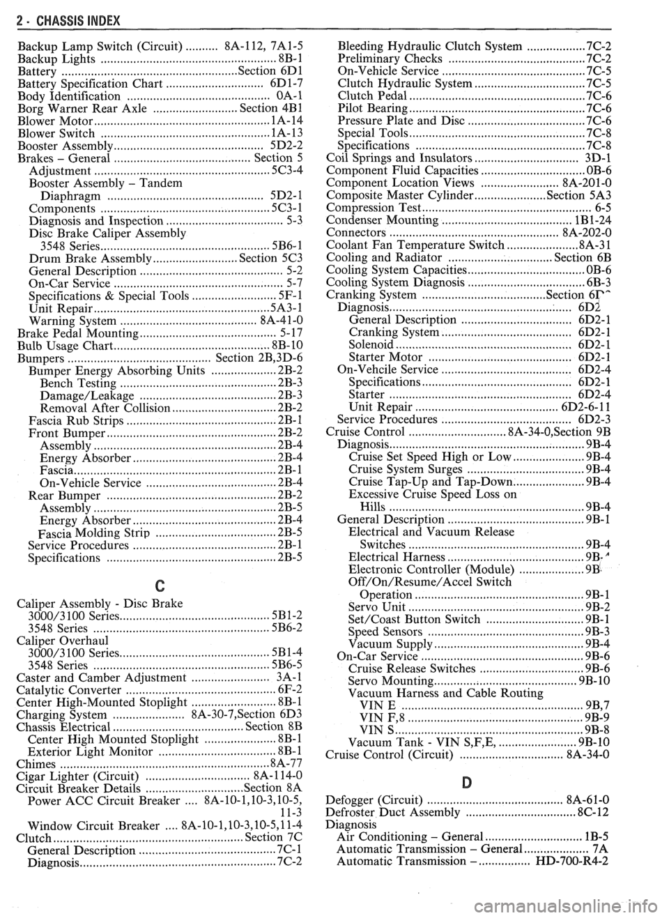
2 - CHASSIS INDEX
Backup Lamp Switch (Circuit) .......... 8A- 1 12. 7A 1-5
Backup Lights
..................................................... 8B-1
...................................................... Battery Section 6D 1
............................ Battery Specification Chart 6D 1-7
.................................... Body Identification ... .... OA- 1
Borg Warner Rear Axle .......................... Section 4B1
...................................................... Blower Motor 1A-14
Blower Switch
.................................................... 1 A- 13
Booster Assembly
............................................. 5D2-2
Brakes
- General ......................................... Section 5
Adjustment
.................................................... 5C3-4
Booster Assembly
. Tandem
Diaphragm
................... .... ..................... 5D2- 1
................................................ Components 5C3- 1
Diagnosis and Inspection
................................. 5-3
Disc Brake Caliper Assembly
.................................................... 3548 Series 5B6-1
Drum Brake Assembly ........................ Section 5C3
General Description
.......................................... 5-2
On-Car Service
.................................................... 5-7
Specifications & Special Tools ......................... .5 F. 1
...................................................... Unit Repair 5A3- 1
.......................................... Warning System 8A-4 1-0
............ Brake Pedal Mounting .. ......................... 5-1 7
Bulb Usage Chart
............................................ 8B-10
............................................ Bumpers Section 2B,3 D.6
Bumper Energy Absorbing Units
.................... 2B-2
Bench Testing
................................................ 2B-3
........................................ Damage/Leakage 2B-3
................................ Removal After Collision 2B-2
............................................. Fascia Rub Strips .2 B. 1
.................................................... Front Bumper 2B-2
Assembly
........................................................ 2B-4
Energy Absorber
........................................... 2B-4
............................................................. Fascia .2 B. 1
On-Vehicle Service
...................................... 2B-4
Rear Bumper
.................................... .... ............ 2B-2
........................................................ Assembly 2B-5
Energy Absorber
............................................ 2B-4
............. .................... Fascia Molding Strip .. 2B-5 ........................................... Service Procedures .2 B. 1
.................................................. Specifications 2B-5
C
Caliper Assembly . Disc Brake
.............................................. 3000/3 100 Series 5B 1-2
3548 Series
...................................................... 5B6-2
Caliper Overhaul
....................... 3000/3 100 Series .. ............... 5B 1-4
3548 Series
.................................................... 5B6-5
Caster and Camber Adjustment
........................ 3A- 1
............................................. Catalytic Converter 6F-2
Center High-Mounted Stoplight
....................... ... 8B- 1
Charging System
...................... 8A.30.7, Section 6D3
Chassis Electrical
.................................... Section 8B
Center High Mounted Stoplight
...................... 8B-1 ................................. Exterior Light Monitor .8 B. 1
................................................................ Chimes 8A-77
................................ Cigar Lighter (Circuit) 8A- 1
14-0
.............................. Circuit Breaker Details Section 8A
Power ACC Circuit Breaker .... 8A- 10.1.10.3.10.5.
11-3
.... Window Circuit Breaker 8A~10~1,10~3.10~5.1 1.4
Clutch
........................................................ Section 7C
......................................... General Description .7 C. 1 ........................................................... Diagnosis 7C-2 Bleeding
Hydraulic Clutch System
................. .7 C.2
Preliminary Checks ..................................... ... 7C-2
On-Vehicle Service
........................................... 7C-5
Clutch Hydraulic System
.................................. 7C-5
Clutch Pedal ...................................................... 7C-6
Pilot Bearing
..................................................... 7C-6
Pressure Plate and Disc
.................................... 7C-6
Special Tools
......................... ....... ................ 7C-8
Specifications
................................................... 7C-8
Coil Springs and Insulators .............................. 3D-1
Component Fluid Capacities
................................ OB-6
Component Location Views
........................ 8A-201-0
Composite Master Cylinder
................... Section 5A3
Compression Test
.................. .. ............................. 6-5
Condenser Mounting
....................................... 1B 1-24
Connectors
.................................................... 8A-202-0
Coolant Fan Temperature Switch
...................... 8A-3 1
Cooling and Radiator
................................ Section 6B
Cooling System Capacities
................................. OB-6
Cooling System Diagnosis
.................................... 6B-3
Cranking System
...................................... Section 6P*
Diagnosis ..................................................... 6~2
General Description ................................ 6D2- 1
Cranking System
........................................ 6D2- 1
Solenoid
................................................... 6D2- 1
Starter Motor ......................................... 6D2-1
On-Vehcile Service
...................................... 6D2-4
Specifications
............................................ 6D2- 1
Starter
........................................................ 6D2-4
Unit Repair
............................................ 6D2-6- 11
Service Procedures
...................................... 6D2-3
Cruise Control
.............................. 8A-34-0, Section 9B
Diagnosis
............................................................ 9B-4
Cruise Set Speed High or Low
.................... 9B-4
Cruise System Surges
.................................. 9B-4
Cruise Tap-Up and Tap-Down
...................... 9B-4
Excessive Cruise Speed Loss on
Hills
........................................................... 9B-4
General Description
........................................ 9B-1
Electrical and Vacuum Release
Switches
...................................................... 9B-4
Electrical Harness
.......................................... 9B-A
Electronic Controller (Module) .................... 9B .
Off/On/Resume/Accel Switch
Operation
.................................................. .91 B-
Servo Unit
.................................................... 9B-2
Set/Coast Button Switch .............................. 9B-1
................................................ Speed Sensors 9B-3
Vacuum Supply
............................................ 9B-4
On-Car Service
.................................................. 9B-6
................................ Cruise Release Switches 9B-6
.......................................... Servo Mounting 9B-10
Vacuum Harness and Cable Routing
VIN
E ................................. .. .................. 9B,7
.................................................... VIN F, 8 9B-9
....................................................... VIN S 9B-8
........................ Vacuum Tank - VIN S,F,E, 9B-10
.............................. Cruise Control (Circuit) 8A-34-0
D
......................................... Defogger (Circuit) $A-6 1-0
..................... ...... Defroster Duct Assembly ... .812 C-
Diagnosis
Air Conditioning
- General ........................... 1B-5
.................... Automatic Transmission - General 7A
Automatic Transmission
- ................ HD-700-R4-2
Page 1823 of 1825
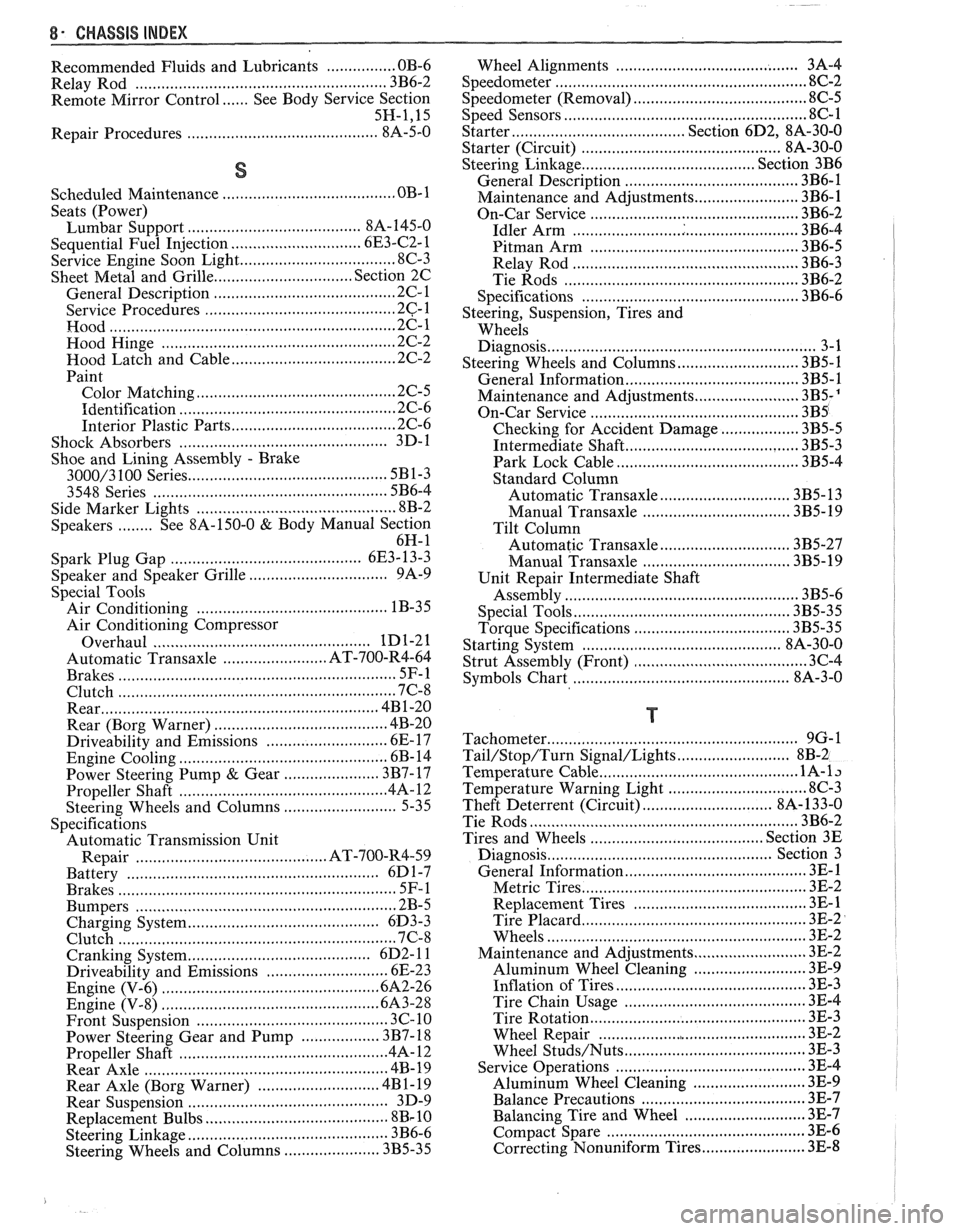
8- CHASSIS INDEX
Recommended Fluids and Lubricants ................ OB-6
Relay Rod
......................................................... 3B6-2
Remote Mirror Control
...... See Body Service Section
5H.1. 15
Repair Procedures
.......................................... 88-50
S
........................................ Scheduled Maintenance OB- 1
Seats (Power) ....................................... Lumbar Support 8A- 145-0
............................. Sequential Fuel Injection 6E3-C2- 1
Service Engine Soon Light
.................................... 8C-3
Sheet Metal and Grille
................................ Section 2C
......................................... General Description .2 C. 1
........................................... Service Procedures .2 C. 1
................................................................. Hood .2 C. 1
...................................................... Hood Hinge 2C-2
Hood Latch and Cable
...................................... 2C-2
Paint
.............................................. Color Matching 2C-5
................................................ Identification -32-6
Interior Plastic Parts ...................................... 2C-6
................................................ Shock Absorbers 3D-
1
Shoe and Lining Assembly
. Brake
............................................ 3000/3 100 Series 5B1-3
3548 Series ...................................................... 5B6-4
Side Marker Lights
.............................................. 8B-2
........ Speakers See 8A- 150-0 & Body
Manual Section
6H- 1
.................... Spark Plug Gap .. .................. 6E3-13-3
................................ Speaker and Speaker Grille 9A-9
Special Tools
............................................ Air Conditioning 1 B-3 5
Air Conditioning Compressor
................................................. Overhaul 1D1-21
........................ Automatic Transaxle AT-700-R4-64
................................................................ Brakes SF-1
Clutch ................................................................ 7C-8
................................................................ Rear 4B1-20
....................................... Rear (Borg Warner) 4B-20
........................... Driveability and Emissions .6 E. 17
................................................ Engine Cooling 6B- 14
Power Steering Pump
& Gear ...................... 3B7-17
............................................... Propeller Shaft .4 A. 12
Steering Wheels and Columns
.......................... 5-35
Specifications Automatic Transmission Unit
............................................ Repair AT-700-R4-59
..................................................... Battery 6D 1-7
................................................................ Brakes 5F-1
Bumpers
......................................................... 2B-5
Charging System
................ .. ................... 6D3-3
.............................................................. Clutch .7 (2.8
....................................... Cranking System 6D2- 1 1
Driveability and Emissions ............................ 6E-23
................................................ Engine (V-6) ..6A 2.26
Engine (V-8) .................................................. 683-28
........................................ Front Suspension 3C- 10
Power Steering Gear and Pump
.................. 3B7-18 ............................................. Propeller Shaft .4 A. 12 ........................................................ Rear Axle 4B-19 ............................ Rear Axle (Borg Warner) 4B 1- 19
Rear Suspension
.............................................. 3D-9
.......................................... Replacement Bulbs 8Br 10 .............................................. Steering Linkage 3B6-6
Steering Wheels and Columns
...................... 3B5-35
........................................ Wheel Alignments 3A-4
....................................................... Speedometer 8C-2
........................................ Speedometer (Removal) 8C-5
...................................................... Speed Sensors 8C-1
Starter ........................................ Section 6D2. 8A-30-0
............................................. Starter (Circuit) 8A-30-0
Steering Linkage ...................................... Section 3B6
....................................... General Description 3B6-1
........................ Maintenance and Adjustments 3B6-1
................................................ On-Car Service 3B6-2
..................................................... Idler Arm 3B6-4
................................................ Pitman Arm 3B6-5
.................................................... Relay Rod 3B6-3
Tie Rods
...................................................... 3B6-2
.................................................. Specifications 3B6-6
Steering, Suspension, Tires and
Wheels Diagnosis
............................................................. 3-1
Steering Wheels and Columns
............................ 3B5-1
..................................... General Information 3B5- 1
Maintenance and Adjustments
...................... 3B5-'
On-Car Service .............................. .. ........... 3B5
Checking for Accident Damage
.................. 3B5-5
Intermediate Shaft ............... .. .................... 3B5-3
Park Lock Cable .......................................... 3B5-4
Standard Column
............................. Automatic Transaxle 3B5-13
Manual Transaxle ................................. 3B5- 19
Tilt Column
.............................. Automatic Transaxle 3B5-27
.................................. Manual Transaxle 3B5-19
Unit Repair Intermediate Shaft
...................................................... Assembly 3B5-6
................................................. Special Tools 3B5-35
Torque Specifications
.................................... 3B5-35
............................................. Starting System 8A-30-0
........................................ Strut Assembly (Front) 3C-4
.................................... ..... Symbols Chart ... 8A-3-0
T
.......................................................... Tachometer 9G-1
Tail/Stop/Turn Signal/Lights .......................... 8B-2
Temperature Cable
.............................................. 112 A-
Temperature Warning Light ................................ 8C-3
Theft Deterrent (Circuit)
.............................. 8A-133-0
Tie Rods
.............................................................. 3B6-2
Tires and Wheels
........................................ Section 3E
Diagnosis
.................................................. Section 3
General Information
......................................... 3E-1
................................................... Metric Tires 3E-2
....................................... Replacement Tires .31 E-
.................................................... Tire Placard 3E-2
........................................................... Wheels 3E-2
Maintenance and Adjustments
.......................... 3E-2
.......................... Aluminum Wheel Cleaning 3E-9
............................. ......... Inflation of Tires .. 3E-3
........................................ Tire Chain Usage 3E-4
.................................................. Tire Rotation 3E-3
.............................................. Wheel Repair 3E-2
...................................... Wheel Studs/Nuts 3E-3
........................................... Service Operations 3E-4
........................ Aluminum Wheel Cleaning 3E-9
.................................... Balance Precautions 3E-7
............................ Balancing Tire and Wheel 3E-7
.............................................. Compact Spare 3E-6
........................ Correcting Nonuniform Tires 3E-8