1988 PONTIAC FIERO warning
[x] Cancel search: warningPage 324 of 1825
DISC BRAKE CALIPER ASSEMBLY 588-3
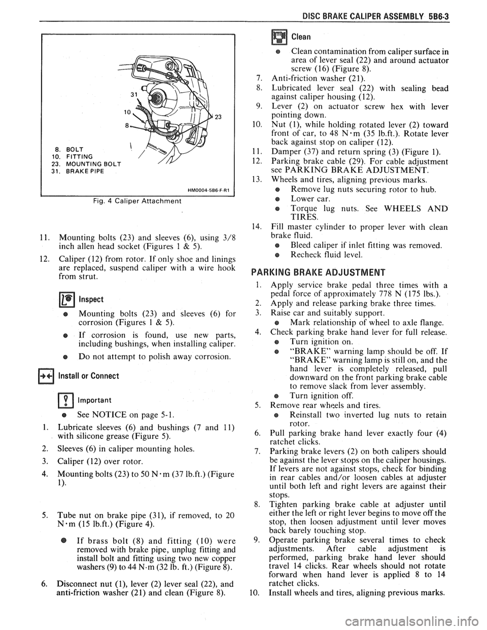
BO LT
FITTING
MOUNTING
31. BRAKE PIPE
Fig. 4 Caliper Attachment
11. Mounting bolts (23) and sleeves (6), using 3/8
inch
allen head socket (Figures 1 & 5).
12. Caliper (12) from rotor. If only shoe and linings
are replaced, suspend caliper with a wire hook
from strut.
Inspect
e Mounting bolts (23) and sleeves (6) for
corrosion (Figures
1 & 5).
e If corrosion is found, use new parts,
including bushings, when installing caliper.
e Do not attempt to polish away corrosion.
Install or Connect
Important
See NOTICE on page 5- 1.
1. Lubricate sleeves (6) and bushings (7 and 11)
with silicone grease (Figure 5).
2. Sleeves
(6) in caliper mounting holes.
3. Caliper (12) over rotor.
4. Mounting bolts (23) to 50 N-m (37 1b.ft.) (Figure
1).
5.
Tube nut on brake pipe (31), if removed, to 20
N-m (15 1b.ft.) (Figure 4).
@ If brass bolt (8) and fitting (10) were
removed with brake pipe, unplug fitting and
install bolt and fitting using two new copper
washers
(9) to 44 N.m (32 lb. ft.) (Figure 8).
6. Disconnect nut (I), lever (2) lever seal (22), and
anti-friction washer (21) and clean (Figure 8).
Clean
Clean contamination from caliper surface in
area of lever seal (22) and around actuator
screw (16) (Figure 8).
7. Anti-friction washer (21).
8. Lubricated lever seal (22) with sealing bead
against caliper housing (12).
9. Lever (2) on actuator screw hex with lever
pointing down.
10. Nut
(I), while holding rotated lever (2) toward
front of car, to 48
N-m (35 1b.ft.). Rotate lever
back against stop on caliper (12).
11. Damper (37) and return spring (3) (Figure 1).
12. Parking brake cable (29). For cable adjustment
see PARKING BRAKE ADJUSTMENT.
13. Wheels and tires, aligning previous marks.
s Remove lug nuts securing rotor to hub.
e Lower car.
e Torque lug nuts. See WHEELS AND
TIRES.
14. Fill master cylinder to proper lever with clean
brake fluid.
e Bleed caliper if inlet fitting was removed.
Recheck fluid level.
PARKING BRAKE ADJUSTMENT
Apply service brake pedal three times with a
pedal force of approximately 778 N (175 lbs.).
Apply and release parking brake three times.
Raise car and suitably support.
e Mark relationship of wheel to axle flange.
Check parking brake hand lever for full release.
e Turn ignition on.
e "BRAKE" warning lamp should be off. If
"BRAKE" warning lamp is still on, and the
hand lever is completely released, pull
downward on the front parking brake cable
to remove slack from lever assembly.
Turn ignition off.
Remove rear wheels and tires.
e Reinstall two inverted lug nuts to retain
rotor.
Pull parking brake hand lever exactly four (4)
ratchet clicks.
Parking brake levers (2) on both calipers should
be against the lever stops on the caliper housings.
If levers are not against stops, check for binding
in rear cables and/or loosen cables at adjuster
until both left and right levers are against their
stops.
Tighten parking brake cable at adjuster until
either the left or right lever begins to move off the
stop, then loosen adjustment until lever moves
back barely touching stop.
Operate parking brake several times to check
adjustments. After cable adjustment is
performed, parking brake hand lever should
travel 14 clicks. Rear wheels should not rotate
forward when hand lever is applied
8 to 14
ratchet clicks.
Install wheels and tires, aligning previous marks.
Page 350 of 1825
ENGINE GENERAL INFORMATION 6-5
INSTRUMENT PANEL OIL WARNING LAMP "ON" AT IDLE
1. Oil cooler, or oil or cooler line restricted. Remove 2. Oil pump pressure low. See oil pump repair
restrictions in cooler or cooler line. procedures
in Section
6A.
ENGINE COMPRESSION EST
COMPRESSION TEST
Important
e Disconnect the "BAT." terminal from the - HE1 distributor or ignition module.
To determine if the valves or pistons are at fault,
a test should be made to determine the cylinder
compression pressure. When checking cylinder
compression, the throttle and choke should be open, all
spark plugs removed, and the battery at or near full
charge. The lowest reading cylinder should not be less
than
70% of the highest and no cylinder reading
should be less than
689 kPa (100 PSI). This
should be done with four
"puffs" per
cylinder.
Normal - Compression builds up quickly and
evenly to specified compression on each cylinder.
Piston Rings - Compression low on first
stroke, tends to build up on following strokes, but does
not reach normal. Improves considerably with addition
of oil.
Valves - Low on first stroke, does not tend to
build up on following strokes. Does not improve much
with addition of oil.
Use approximately three squirts from a plunger
type oiler.
Page 414 of 1825
ENGINE COOLING 88.3
since a small oil pump driven by the separator plate
forces the silicone oil into a reservoir between the
separator plate and the front cover assembly. In this
position, the passage from this cavity to the clutch area
is closed by a slide valve. As operating conditions
produce a high radiator air temperature discharge,
above approximately 66°C
(150"F), the temperature
sensitive bi-metal coil tightens to move the slide valve
(attached to the coil) which opens a port in the
separator plate. This allows a flow of silicone oil into
the clutch chamber to engage the clutch, providing a
maximum fan speed of approximately 2200 rpm. The
clutch coil is calibrated so that, with a road load at an
ambient temperature of approximately 32°C
(90T), the
clutch is just at a point of shift between high and low
fan speed. No attempt should be made to disturb the
calibration of the engine clutch fan assembly as each
assembly is individually calibrated at the time of
manufacture. Under certain temperature conditions
there is a lateral movement at the fan tip which should
not be considered as a hub or bearing failure. This
condition is a design feature of the clutch assembly
which allows up to approximately
1/4" lateral
movement measured at the fan tip.
Testing a clutch fan by holding the small hub
with one hand and rotating the aluminum housing in
a
clockwise/counter-clockwise motion will cause the
clutch to freewheel, which is a normal condition when
operated in this manner. This should not be considered
a test by which replacement is determined.
Temperature Switch
This switch activates a warning lamp in the
instrument cluster if the engine overheats. With
optional instrumentation, a temperature gage replaces
the warning lamp and the temperature switch is
replaced with a transducer. See Section
8A for
Temperature Switch location and diagnosis.
Coolant Temperature Fan Switch
This switch regulates voltage to the coolant fan
relay, which operates the fan whenever the engine
coolant temperature exceeds 230"
F (110" C). For
location and diagnosis see Section 8A for Coolant
Temperature Fan Switch.
Thermostat
A pellet-type thermostat is used in the coolant
outlet passage to control the flow of engine coolant, to
provide fast engine warm-up and to regulate coolant
temperatures.
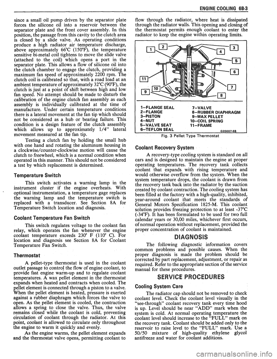
A wax pellet element in the thermostat
expands when heated and contracts when cooled. The
pellet element is connected through a piston to a valve.
When the pellet element is heated, pressure is exerted
against a rubber diaphragm which forces the valve to
open. As the pellet element is cooled, the contraction
allows a spring to close the valve. Thus, the valve
remains closed while the coolant is cold, preventing
circulation of coolant through the radiator. At this
point, coolant is allowed to circulate only throughout
the engine to warm it quickly and evenly.
As the engine warms, the pellet element expands
and the thermostat valve opens, permitting coolant to flow
through the radiator, where heat is dissipated
through the radiator walls. This opening and closing of
the thermostat permits enough coolant to enter the
radiator to keep the engine within operating limits.
Fig. 3 Pellet Type Thermostat
Coolant Recovery System
A recovery-type cooling system is standard on all
cars and is designed to maintain the engine at proper
operating temperatures. The recovery tank collects
coolant that expands with rising temperature and
would otherwise overflow from the system. When the
system temperature drops, the coolant is drawn from
the recovery tank back into the radiator by the suction
created by coolant contraction. The cooling system has
been filled at the factory with a high-quality, inhibited,
year-around coolant that meets the standards of
General Motors Specification 1825-M. This coolant
solution provides freezing protection to at least -37°C
(-34°F). It has been formulated to be used for two full
calendar years or
30,OO miles, whichever first occurs,
of normal operation without replacement, provided the
proper concentration of coolant is maintained.
DIAGNOSIS
The following diagnostic information covers
common problems and possible causes. When the
proper diagnosis is made the problem should be
corrected by part replacement, adjustment, or repair as
required. Refer to the appropriate section of the service
manual for these procedures.
SERVICE PROCEDURES
Cooling System Care
The radiator cap should not be removed to check
coolant level. Check the coolant level visually in the
"see-through" coolant recovery tank every time hood
is up. Level should be near "ADD" mark when the
system is cold. At normal operating temperature the
coolant level should increase to the "FULL" mark on
the recovery tank. Coolant should be added only to the
reservoir to raise level to the "FULL" mark. Use a
50/50 mixture of high-quality ethylene glycol
antifreeze and water for coolant additions.
Page 1166 of 1825
CONTENTS
ELECTRICAL DIAGNOSIS
Cell
1
2
3
4 5
10
11
12 14
20
21
22
23
30
31
33
34
40
4
1
60
61
62
63
64
65
66
67
68
Index
Introduction
Symbols
Troubleshooting Procedures Repair Procedures
Power Distribution
Fuse Block Details
Light Switch Details
Ground Distribution
Engine:
V6 VIN S
Engine: V8 VIN
F
Engine: V8 VIN E
Engine:
V8 VIN 8
Starter and Charging System
Coolant Fans
Vehicle Speed Sensor
Cruise Control Horns
Brake Warning System
Heater
Defogger
Air Conditioning: System Check
Air Conditioning: Blower Controls
Air Conditioning: Compressor Controls
Air Conditioning: Air Delivery
Air Conditioning: Blower Controls
Air Conditioning: Compressor Controls
Air Conditioning: Air Delivery Cell
77
8
1
82
86 90
9
1
100
102
103
110
111
112
114
117
120
130
133
134
135
141
143
145
150
151
201 202
203
Warnings and Alarms: Chime
Instrument Panel: Gages Cluster
Instrument Panel:
Digital Cluster
Driver Information Center
(DIC)
WiperlWasher
WiperlWasher: Pulse
Headlights
Headlight Doors
Headlights with Lamp Monitor
Exterior Lights
Exterior Lights with Lamp Monitor
Back Up Lights
Interior Lights
Interior Lights Dimming
Power Windows
Power Door Locks
Theft Deterrent
Hatch Release
Hatch Pull-Down
Power Mirrors
Automatic Day-Night Mirror
Lumbar Support
Radio Power Antenna
Component Location Views
Harness Connector Faces
Harness Routing Views
Page 1167 of 1825
Page
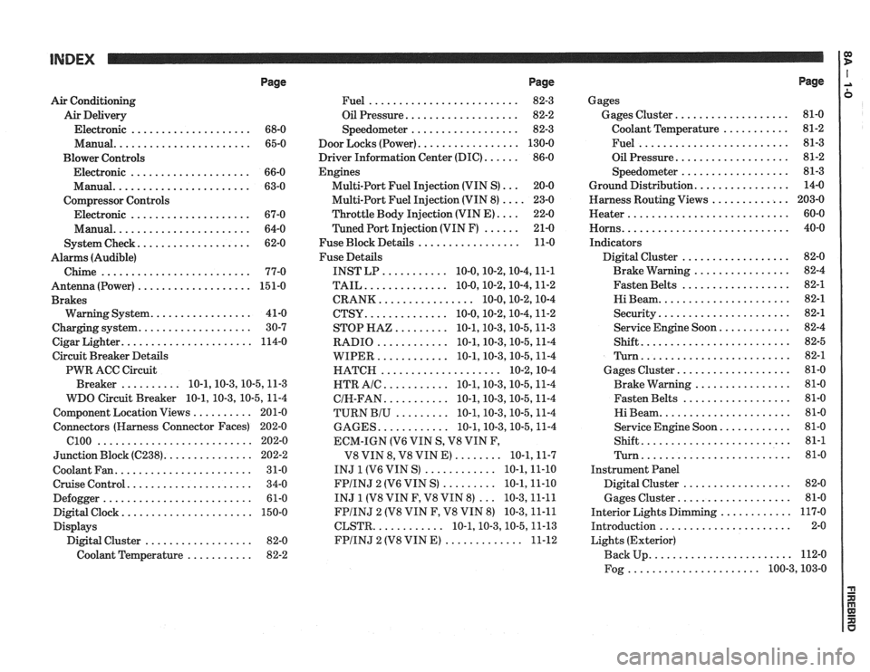
Air Conditioning
Air Delivery
Electronic
.................... 68-0
Manual
....................... 65-0
Blower Controls
Electronic
.................... 66-0
Manual
....................... 63-0
Compressor Controls Electronic
.................... 67-0
Manual
....................... 64-0
................... System Check 62-0
Alarms (Audible)
Chime
......................... 77-0
Antenna(Power) ................... 151-0
Brakes
................. Warning System 41-0
................... Charging system 30-7
...................... Cigar Lighter 114-0
Circuit Breaker Details
PWR ACC Circuit
.......... Breaker 10.1.10.3.10.5.1 1.3
WDO Circuit Breaker
10.1. 10.3. 10.5. 11-4
.......... Component Location Views 201-0
Connectors (Harness Connector Faces) 202-0
el00 .......................... 202-0
............... Junction Block ((2238) 202-2
Coolant Fan
....................... 31-0
Cruise Control
..................... 34-0
Defogger
......................... 61-0
Digital Clock
...................... 150-0
Displays Digital Cluster
.................. 82-0
Coolant Temperature
........... 82-2
Page
......................... Fuel 82-3
................... Oil Pressure 82-2
.................. Speedometer 82-3
................. Door Locks (Power) 130-0
...... Driver Information Center (DIC) 86-0
Engines
... Multi-Port Fuel Injection (VIN S) 20-0
.... Multi-Port Fuel Injection (VIN 8) 23-0
.... Throttle
Body Injection (VIN E) 22-0
...... Tuned
Port Injection (VIN F) 21-0
................. Fuse Block Details 11-0
Fuse Details
........... INST LP 10.0.10.2.10.4.1 1.1
.............. TAIL 10.0.10.2.10.4.1 1.2
................ CRANK 10.0.10.2.1 0.4
.............. CTSY 10~0.10.2.10.4.1 1.2
......... STOP HAZ 10.1.10.3.10.5.1 1.3
............ RADIO 10.1.10.3.10.5.1 1.4
............ WIPER 10.1.10.3.10.5.1 1.4
.................... HATCH 10.2.1 0.4
........... HTR AlC 10.1.10.3.10.5.1 1.4
........... CIH.FAN 10.1.10.3.10.5.1 1.4
......... TURN BIU 10.1.10.3.10.5.1 1.4
............ GAGES 10.1.10.3.10.5.1 1.4
ECM-IGN
(V6 VIN S. V8 VIN F.
........ V8 VIN 8. V8 VIN E) 10.1.1 1.7
............ INJ 1 (V6 VIN S) 10.1.1 1.10
......... FPIINJ 2 (V6 VIN S) 10.1.1 1.10
... INJ 1 (V8 VIN F. V8 VIN 8) 10.3.1 1.11
FPIINJ 2 (V8 VIN F. V8 VIN 8) 10.3.1 1.11
............ CLSTR 10.1.10.3.10.5.1 1.13
............. FPIINJ 2 (V8 VIN E) 11-12
Page
Gages
................... Gages Cluster 81-0
........... Coolant Temperature 81-2
......................... Fuel 81-3
................... Oil Pressure 81-2
.................. Speedometer 81-3
................ Ground Distribution 14-0
Harness Routing Views
............. 203-0
........................... Heater 60-0
............................ Horns 40-0
Indicators
.................. Digital Cluster 82-0
................ Brake Warning 82-4
.................. Fasten Belts 82-1
...................... Hi Beam 82-1
...................... Security 82-1
............ Service Engine Soon 82-4
......................... Shift 82-5
......................... Turn 82-1
................... Gages Cluster 81-0
................ Brake Warning 81-0
.................. Fasten Belts 81-0
...................... Hi Beam 81-0
............ Service Engine Soon 81-0
......................... Shift 81-1
......................... Turn 81-0
Instrument Panel
Digital Cluster
.................. 82-0
Gages Cluster
................... 81-0
............ Interior Lights Dimming 117-0
...................... Introduction 2-0
Lights (Exterior)
........................ Back Up 112-0
...................... Fog 100.3,10 3.0
Page 1168 of 1825
INDEX
Page
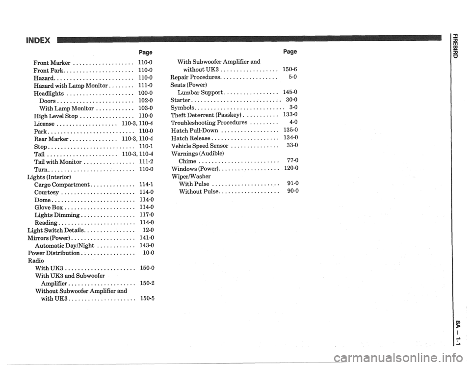
................... Front Marker 110-0
...................... Frontpark 110-0
......................... Hazard 110-0
........ Hazard with Lamp Monitor 111-0
..................... Headlights 100-0
........................ Doors 102-0
............ With Lamp Monitor 103-0
................. Nigh Level Stop 110-0
................... License 110.3,11 0.4
Park
........................... 110-0
............... Rear Marker 110.3,11 0.4
stop
........................... 110-1
...................... Tail 110.3,11 0.4
................ Tail with Monitor 111-2
Turn ........................... 110-0
Lights (Interior)
.............. Cargo Compartment 114-1
....................... Courtesy 114-0
.......................... Dome 114-0
...................... Glove Box 114-0
................. Lights Dimming 117-0
........................ Reading 114-0
................ Light Switch Details 12-0
.................... Mirrors (Power) 141-0
Automatic
DayINight ............ 143-0
................. Power Distribution 10-0
Radio
...................... With UK3 150-0
With
UK3 and Subwoofer
..................... Amplifier 15 0-2
Without Subwoofer Amplifier and
with
UK3 ..................... 150-5 With
Subwoofer Amplifier and
without UK3
..................
.................. Repair Procedures
Seats (Power)
Lumbar Support
.................
Starter ............................
........................... Symbols
........... Theft Deterlent (Passkey)
......... Troubleshooting Procedures
.................. Hatch Pull-Down
..................... Hatch Release
............... Vehicle Speed Sensor
Warnings (Audible)
Chime
.........................
................... Windows (Power)
WiperIWasher
With Pulse .....................
................... Without Pulse
Page
Page 1303 of 1825
STARTER AND CHARGING SYSTEM
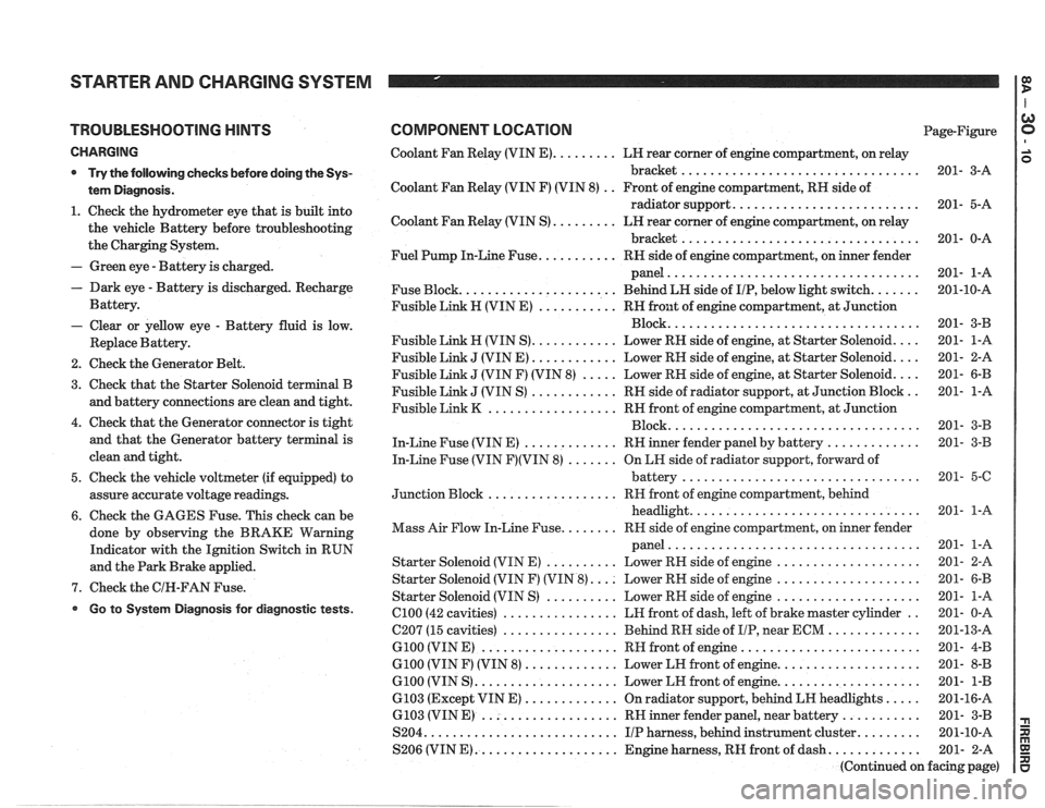
TROUBLESHOOTING HINTS
CHARGING
* Try the following checks before doing the Sys-
tem Diagnosis
.
1 . Check the hydrometer eye that is built into
the vehicle Battery before troubleshooting
the Charging System
.
- Green eye . Battery is charged .
. Dark eye . Battery is discharged . Recharge
Battery
.
- Clear or yellow eye . Battery fluid is low .
Replace Battery .
2 . Check the Generator Belt .
3 . Check that the Starter Solenoid terminal B
and battery connections are clean and tight
.
4 . Check that the Generator connector is tight
and that the Generator battery terminal is
clean and tight
.
5 . Check the vehicle voltmeter (if equipped) to
assure accurate voltage readings
.
6 . Check the GAGES Fuse . This check can be
done by observing the BRAKE Warning
Indicator with the Ignition Switch in RUN
and the Park Brake applied
.
7 . Check the GIN-FAN Fuse .
Go to System Diagnosis for diagnostic tests .
COMPONENT LOCATION Page-Figure
Coolant Fan Relay (VIN
E) ......... LH rear corner of engine compartment. on relay
bracket
................................. 201- 3-A
Coolant Fan Relay (VIN F) (VIN 8)
. . Front of engine compartment. RH side of
radiator support
.......................... 201- 5-A
Coolant Fan Relay (VIN S)
......... LN rear corner of engine compartment. on relay
bracket
................................. 201- 0-A
Fuel Pump In-Line Fuse
........... RH side of engine compartment. on inner fender
panel
................................... 201- 1-A
Fuse Block
...................... Behind LN side of IIP. below light switch ....... 201-10-A
Fusible Link H (VIN E)
........... RH front of engine compartment. at Junction
................................... Block 201- 3-B
Fusible Link
H (VIN S) ............ Lower RN side of engine. at Starter Solenoid .... 201- 1-A
Fusible Link
J (VIN E) ............ Lower RH side of engine. at Starter Solenoid .... 201- 2-A
Fusible Link
J (VIN F) (VIN 8) ..... Lower RH side of engine. at Starter Solenoid .... 201- 6-B
Fusible Link
J (VIN S) ............ RH side of radiator support. at Junction Block .. 201- 1-A
Fusible Link
K .................. RH front of engine compartment. at Junction
................................... Block 201- 3-B
In-Line Fuse (VIN E)
............. RH inner fender panel by battery ............. 201- 3-B
In-Line Fuse (VIN
F)(VIN 8) ....... On LH side of radiator support. forward of
................................. battery 201- 5-6
.................. Junction Block RH
front of engine compartment. behind
................................ headlight 201- 1-A
........ Mass Air Flow In-Line Fuse RR side of engine compartment. on inner fender
................................... panel 201- 1-A
Starter Solenoid (VIN E)
.......... Lower RH side of engine .................... 201- 2-A
Starter Solenoid (VIN F) (VIN
8) .... Lower RH side of engine .................... 201- 6-B
Starter Solenoid (VIN S)
.......... Lower RN side of engine .................... 201- 1-A
el00 (42 cavities) ................ LH front of dash. left of brake master cylinder .. 201- 0-A
C207 (15 cavities)
................ Behind RH side of IIP. near ECM ............. 201-13-A
G100 (VIN E) ................... RH front of engine ......................... 201- 4-B
G100 (VIN F) (VIN 8) ............. Lower LH front of engine .................... 201- 8-B
G100 (VIN S) .................... Lower LH front of engine .................... 201- 1-B
6103 (Except VIN E) ............. On radiator support. behind LH headlights ..... 201-16-A
6.103 (VIN E) ................... RH inner fender panel. near battery ........... 201- 3-B
S204
........................... IIP harness. behind instrument cluster ......... 201-10-A
S206 (VIN
E) .................... Engine harness. RH front of dash ............. 201- 2-A
(Continued on facing page)
Page 1333 of 1825
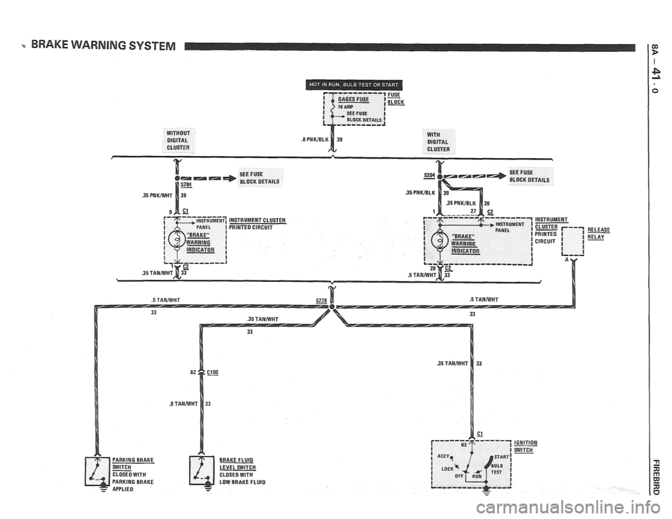
BRAKE WARNING SYSTEM
INSTRUMENT CLUSTER
PRINTED CIRCUIT
.5 TANAIVHT
BRAICE FLUID
LEVEL SWITCH
LOW BRAKE FLUID
RELEASE
RELAY