1988 PONTIAC FIERO jump start
[x] Cancel search: jump startPage 1515 of 1825

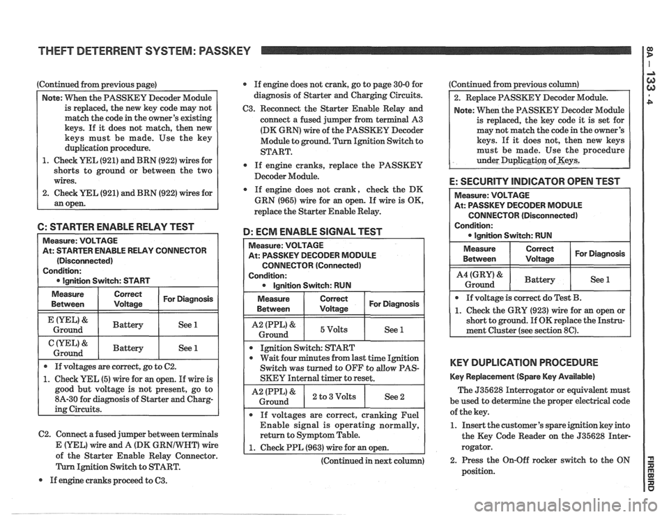
Continued from previous page)
Note: VVhen the PASSKEY Decoder Module
is replaced, the new key code may not
match the code in the owner's existing
keys. If it does not match, then new
keys must be made. Use the key
duplication procedure.
1. Check YEL (921) and BRN (922) wires for
shorts to ground or between the two
wires.
2. Check
UEL (921) and BRN (922) wires for
an open. If
engine does not crank, go to page 30-0 for
diagnosis of Starter and Charging Circuits.
C3. Reconnect the Starter Enable Relay and
connect a fused jumper from terminal A3
(DK GRN) wire of the PASSKEY Decoder
Module to ground. Ignition Switch to
START.
0 If engine cranks, replace the PASSKEY
Decoder Module.
If engine does not crank, check the DK
GRN (965) wire for
an open. If wire is OK,
replace the Starter Enable Relay.
6: STARTER ENABLE RELAY TEST
D: ECM ENABLE SIGNAL TEST
C2. Connect a fused jumper between terminals
Measure: VOLTAGE
At: STARTER ENABLE RELAY CONNECTOR
(Disconnected)
Condition:
0 Ignition Switch: START Measure:
VOLTAGE
At: PASSKEY DECODER MODULE
CONNECTOR (Connected)
Condition: 0 Ignition Switch: RUN
Measure
Between
&
Ground
&
Ground
Measure
Between I I For Diagnosis ( Voltage
1 I 5Volts I See 1 1
If voltages are correct, go to C2.
1. Check YEL (5) wire for an open. If wire is
good but voltage is not present, go to
8A-30 for diagnosis of Starter and Charg-
ing Circuits.
Correct
Voltage
Battery
Battery
I I
Ignition Switch: START
For Diagnosis
See 1
See 1
0 wait four minutes from last time Ignition
Switch was turned to OFF to
allow PAS-
SKEY Internal timer to reset.
I A2 IPPL)& ) 2 to3Volts I See2 i Ground
If voltages are correct, cranking Fuel
Enable signal is operating normally,
return to Symptom Table.
E (YEL) Vfire and A (DK GR wire 1 1. Check PPL (963) wire for an open. A of the Starter Enable Relay Connector. I I
(Continued in next column)
Ignition Switch to START.
If engine cranks proceed to
63.
Continued from previous column)
2. Replace PASSKEY Decoder Module.
Note: When the PASSKEY Decoder Module
is replaced, the key code
it is set for
may not match the code in the owner's
keys. If
it does not, then new keys
must be made. Use the procedure
under
Duplicgti~n of-Keys2
E: SECURITY INDICATOR OPEN TEST
CONNECTOR (Disconnected)
Condition:
KEY DUPLICATION PROCEDURE
Key Replacement (Spare Key Available)
The 535628 Interrogator or equivalent must
be used to det e
the proper electrical code
of the key.
1. Insert the customer's spare ignition key into
the Key Code Reader on the 535628 Inter-
rogator.
2. Press the On-Off rocker switch to the ON
position.
Page 1821 of 1825

6- CHASSIS INDEX
Upper Air Outlet Deflectors ...................... 8C-12
Interior Lights ............................................. 8A- 1 17-0
Intermediate Shaft (Steering Column)
.............. 3B5-3
J
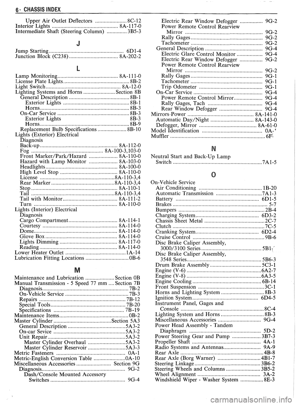
Jump Starting .................................................... 6D 1-4
Junction Block
((2238) ................................. 8A-202-2
L
Lamp Monitoring ......................................... 8A- 1 1 1-0
License Plate Lights .............................................. 8B-2
Light Switch
.................................................... 8A- 12-0
Lighting Systems and Horns
...................... Section 8B
General Description ......................................... .8 B- 1
Exterior Lights
............................................ 8B- 1
Horns ....................... .. ................................. 8B-3
On-Car Service
.................................................. 8B-3
Exterior Lights 8B-3
Horns
.............................................................. 8B-9
Replacement Bulb Specifications .................... 8B-10
Lights (Exterior) Electrical Diagnosis
Back-up
...................................................... 8A- 1 12-0
Fog ............................................... 8A- 100.3,10 3.0
Front
Marker/Park/Hazard .................... 8A-110-0
Hazard with Lamp Monitor .................... 8A-103-0
Headlights .................................................. 8A- 100-0
High Level Stop
..................................... 8A-110-0
License .................................................. .8A.110.3, 4
Rear Marker
........................................... .8 A. 1 10.3, 4
Stop ........................................................... 8A-110-1
Tail ......................................................... .8 A. 1 10.3, 4
Tail with Monitor
................ .... ........... 8A- 1 1 1-2
Turn
......................................................... 8A- 1 10-0
Lights (Interior) Electrical
Diagnosis Cargo Compartment
............................. 8A- 1 14- 1
Courtesy
................................................. 8A- 1 14-0
Dome
.................................. .. ...................... 8A- 1 14-0
Glove Box .................................................. 8A- 1 14-0
Lights Dimming
...................................... 8A- 1 17-0
Reading
...................................................... 8A- 1 14-0
Lower Heater Outlet
........................................ 1A-14
Lubrication Fitting Locations .............................. OB-6
M
Maintenance and Lubrication .................... Section OB
Manual Transmission
. 5 Speed 77 mm .... Section 7B
Diagnosis
........... .. ............................................ 7B-2
On-Vehicle Service
.......................................... 7B-3
Repairs
................................... .... .................... 7B- 12
Special Tools
................................................. 7B-20
. Specifications .............................................. 7B 19
Maintenance Items
................................................ OB-2
Master Cylinder
........................................ Section 5A3
General Description
...................................... ..5A 3.2
On-car Sevice
................................................ 5A3-2
Unit Repair ..................................................... .5A 3.2
Master Cylinder Overhaul
......................... .5A 3.2
Master Cylinder Reservoir
......................... .5A 3.3
Metric Fasteners
................................................ OA- 1
Metric-English Conversion Table ..................... .O A. 10
Miscellaneous Accessories
........................ Section 9G
Diagnosis
.......................................................... 9G-2
Dash/Console Mounted Accessory
Switches
.................................................... 9G-4 Electric
Rear Window Defogger
................ 9G-2
Power Remote Control
Rearview
......................... Mirror ...................... .. 9G-2
Rally Gages
................................................. 9G-2
Tachometer
.................................................. 9G-2
..................................... General Description 9G-4
Electric Glare Control Monitor
.................. 9G-4
Electric Rear Window Defogger
................ 9G-2
Power Remote Control
Rearview
Mirror ..................................................... 9G-2
Rally Gages
................................................. 9G-1
Tachometer
................................................. 9G-1
Trip Odometer
............................................ 9G-1
............................................. On-Car Service 9G-4
Power Remote Control Mirror
.................... 9G-4
Rally Gages. Tach
..................................... 9G-4
Rear Window Defogger
.............................. 9G-4
Mirrors..Power ............................................ 8A- 141-0
Automatic
Day/Night ............................. 8A- 143-0
..................................... Defogger. Mirror 8A-61-0
.......................................... Model Identification OA-'
Muffler ................................................................. 6Fi
N
Neutral Start and Back-Up Lamp
Switch
...................................... ..
0
On-Vehicle Service
Air Conditioning
.................................... ... . 1B-20
Automatic Transmission
............................... .7A 1.3
Battery
........................................................ 6D1-5
................................ ......................... Brakes ... 5-7
Bumpers
......................................................... 2B-4
Charging System
.............................. ... ........... 6D3-2
Chassis Sheet Metal
.......................................... 2C-7
Clutch
................................................................ 7C-5
Cranking System
............................................ 6D2-4
Cruise Control ............................................... 9B-6
Disc Brake Caliper Assembly,
3000/3 100 Series .......................................... 5BliC
Disc Brake Caliper Assembly,
3548 Series
................................................... 5B6-3
Drum Brake Assembly .................................... 5C3-1
Engine (V-6) .................................................... 6A2-7
Engine (V-8) ................................................ -6A3-5
Engine Cooling ....................................... .. .... 6B- 14
Front Suspension
........................................... 3C-1
Horns and Lighting System .............................. 8B-3
Ignition System
.............................................. 6D4-5
Instrument Panel, Gages and
Console
.......................................................... 8C-4
Lighting System and Horns
.......................... .... 8B-3
Miscellaneous Accessories
.......................... .... 9G-4
Power Head Assembly
. Tandem
Diaphragm
................................................. 5D-2
Power Steering Gear and Pump
.................... 3B7-3
Propeller Shaft
............................................. 4A-1
.......................... Radio Systems and Antennas 9A-9
Rear Axle
.......................................................... 4B-8
Rear Axle (Borg Warner)
........................... ... 4B 1-7
Steering Linkage ............................................. 3B6-2
........................ Steering Wheels and Columns 3B5-2
Wheel Alignment
......................................... 3A-2
Windshield Wiper
- Washer System ................ 8E-3