1988 PONTIAC FIERO engine overheat
[x] Cancel search: engine overheatPage 472 of 1825
IGNITION SYSTEM 6B4-3
flash-over, which causes engine misfiring. Do not
mistake corona discharge for flash-over, or a shorted
insulator. Corona is a steady blue light appearing
around the insulator, just above the shell crimp. It is
the visible evidence of a high-tension field and has no
effect on ignition performance. Usually it can be
detected only in darkness. This discharge may repel
dust particles, leaving a clear ring on the insulator just
above the shell. This ring is sometimes mistakenly
regarded as evidence that combustion gases have blown
out between shell and insulator.
lgnition Switch
The mechanical switch is located in the steering
column on the right hand side just below the steering
wheel. The electrical switching portion of the assembly
is separate from the key and lock cylinder. However,
both are synchronized and work in conjunction with
each other through the action of the actuator rod
assembly.
For a complete explanation of the key and lock
cylinder, and the actuator rod assembly, see
STEERING, Section
38. See Section 8 for electrical
switching.
DIAGNOSIS
IGNITION SYSTEM
Spark Plugs
Worn or dirty plugs may give satisfactory
operation at idling speed, but at higher RPM they
frequently fail. Faulty plugs are indicated in a number
of ways: poor fuel economy, power loss, loss of speed,
hard starting and generally poor engine performance.
Spark plugs may also fail due to carbon fouling,
excessive gap, or a broken insulator. Fouled plugs may
be indicated by black carbon
deposits. The black deposits are usually the result of
slow-speed driving and short runs, where sufficient
engine operating temperature is seldom reached. Worn
pistons, rings, faulty ignition, over-rich carburetion
and spark plugs which are too cold will also result in
carbon deposits.
Excessive gap wear, on plugs of low mileage,
usually indicates the engine is operating at high speeds,
or loads that are consistently greater than normal, or
that a plug which is too hot is being used. Electrode
wear may also be the result of plug overheating,
causcd
by combustion gases leaking past the threads due to
insufficient torquing of the spark plug. Excessively lean
carburetion will also result in accelerated electrode
wear.
Broken insulators are usually the result of
improper installation, or carelessness when regapping
the plug. Broken upper insulators usually result from
a poor fitting wrench, or an outside blow. The cracked
insulator may not show up right away, but will as soon
as oil or moisture penetrates the crack. The crack is
usually just below the crimped part of shell and may
not be visible.
Broken lower insulators usually result from
carelessness when regapping and generally are visible.
This type of break may result from the plug operating
too "hot", which may happen in periods of high-speed
operation or under heavy loads. When regapping a
spark plug, always make the gap adjustment by
bending the ground (side) electrode. Spark plugs with
broken insulators should always be replaced.
HE1 Distributor
See Unit Repair for distributor disassembly, test
and reassembly of individual distributor components,
when the distributor is removed from the vehicle. See
On-Car Service for distributor removal and installation
and for component removal with distributor in car. See
Section 6E for
HE1 and EST diagnosis.
SERVICE PROCEDURES
IGNITION SYSTEM
Distributor Ignition
NOTICE: This procedure is generally true for
most carlines. Where procedure is different, or
where additional information is required, see
"ON-CAR SERVICE" for specific
carline.
HE1 DISTRIBUTOR
Service Precautions
1. When making compression checks, disconnect
the ignition switch feed wire at the distributor.
When disconnecting this connector,
do not use
a screwdriver or tool to release the locking tab, as
it may break.
2. No periodic lubrication is required. Engine oil
lubricates the lower bushing and an oil-filled
reservoir provides lubrication for the upper
bushing. 3.
The tachometer (TACH) terminal is next to the
ignition switch (BAT) connector on the
distributor cap.
NOTICE: The tachometer terminal must
NEVER be allowed to touch ground, as damage
to the module and/or ignition coil can result.
Some tachometers currently in use may NOT be
compatible with the High Energy Ignition System.
Consult the manufacturer of the tachometer if
questions arise.
4. Dwell adjustment is controlled by the module,
and cannot be adjusted.
5. The material used to construct the spark plug
cables is very soft. This cable will withstand more
heat and carry a higher voltage, but scuffing and
cutting become easier. The spark plug cables
must be routed correctly to prevent
chafing or
cutting. See Spark Plug Section. When removing
Page 551 of 1825
6EZ-B-4 5.OL (VIN E) DRIVEABILITY AND EMISSIONS
DEWNATION 1 SPARK KNOCK
Definition: A mild to severe ping, usually worse under acceleration. The
engine makes sharp metallic knocks that change with throttle opening.
@ CHECK for obvious overheatingproblems. - For proper transmission shift points. See Section
- Low coolant. "7".
- Loose water pump belt. - TCC operation. See CHART C-8.
- Restricted air flow to radiator, or restricted - For incorrect basic engine parts such as cam,
water flow thru radiator. heads,
pistons, etc.
- Faulty or incorrect thermostat. - Excessive oil entering combustion chamber.
- Coolant sensor, which has shifted in value. @ Remove carbon with top engine cleaner. Follow
- Correct coolant solution - should be a 50150 instructions on can.
mix of GM
#lo52753 anti-freeze coolant (or @ If there is spray from only one injector, then there
equiv.) and water. is
a malfunction in the injector assembly, or in the
@ CHECK: signal to the injector assembly. The malfunction
- For poor fuel quality, proper octane rating. can be isolated by switching the injector
- For correct PROM. connectors. If the problem remains with the
- Spark plugs for correct heat range.
original injector, after switching the connector,
- ESC system opeation. See CHART C-5.
then the injector is defective. Replace the injector.
- Ignition timing. See Vehicle Emission Control
If the problem moves with the injector connector,
Information label. then the
problem is an improper signal in the
- Fuel system for low pressure. See CHART A-7.
injector circuits. See CHART A-3.
- Check EGR svstem. - CHART C-7.
HESITATION, SAG, STUMBLE
Definition: Momentary lack of response as the accelerator is pushed down.
Can occur at all car speeds.
C'sually most severe when first trying to make the car
move, as from a stop sign.
May cause the engine to stall if severe enough.
@ Perform careful visual (physical) check, as Information" label.
described at start of Section
"B". - Generator output voltage. Repair if less than 9 or
@ CHECK: more than 16 volts.
- Fuel pressure. See CHART A-7. - For open ignition system ground, CKT 453.
- Water contaminated fuel. - Canister purge system for proper operation. See
- TPS for binding or sticking.
Section "C3".
- Ignition timing. See "Emission Control - EGR valve operation, CHART C-7.
CU"F OUT, MISSES
Definition: Steady pulsation or jerking that follows engine
speed, usually more pronounced as engine load increases. The
exhaust has a steady spitting sound at idle or low speed.
@ Perform careful visual (physical) check, us
described at start of Section
"B".
@ If ignition system is suspected of causing a miss
at idle or cutting, out under load:
@ Check for missing cylinder by:
1. Disconnect IAC motor. Start engine.
Remove one spark plug wire at a time, using
insulated pliers.
2. If there is an rpm drop on all cylinders, (equal
to within 50
rpm), go to "Rough, Unstable, Or
Incorrect Idle, Or Stalling" symptom.
Reconnect
IAC motor.
3. If there is no rpm drop on one or more
cylinders, or excessive variation in drop, check
for spark, on the suspected
cylinder(s) with J
26792 (ST-1251 spark tester or equivalent. If no
spark, see Section
"6D" for "Intermittent Operation
or Miss". If there is spark, remove spark plug(s) in
these cylinders and check for:
- Cracks
- Wear
- Improper gap
- Burned electrodes
- Heavy deposits
- Perform compression check on
questionable cylinder.
@ Check wire resistance (shoulcl not exceed 30,000
ohms), also, check rotor and distributor cap.
Page 613 of 1825
6EZ-C6-2 5.OL (VIN E) DRIVEABILITY AND EMISSIONS
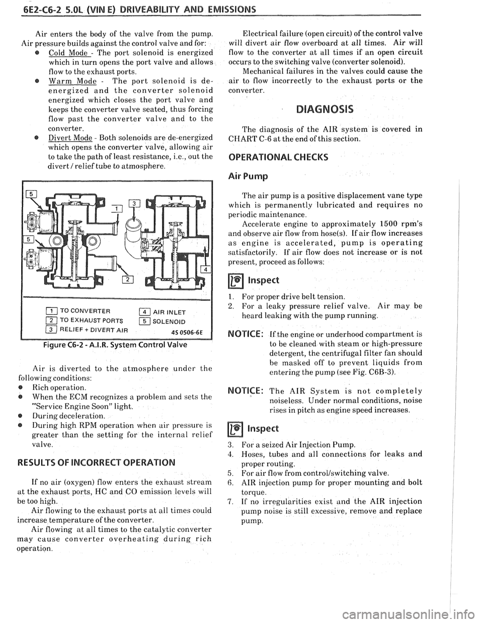
Air enters the body of the valve from the pump.
Air pressure builds against the control valve and for:
@ Cold Mode - The port solenoid is energized
which in turn opens the port valve and allows
flow to the exhaust ports.
@ Warm Mode - The port solenoid is de-
energized and the converter solenoid
energized which closes the port valve and
keeps the converter valve seated, thus forcing
flow past the converter valve and to the
converter.
@ Divert Mode - Both solenoids are de-energized
which opens the converter valve, allowing air
to take the path of least resistance,
i.e., out the
divert
/ relief tube to atmosphere.
TO CONVERTER AIR INLET
1 TO EXHAUST PORTS 1 SOLENOID / RELIEF + DIVERT AIR 45 0506-6E
Figure C6-2 - A.I.R. System Control Valve
Air is diverted to the atmosphere under the
following conditions:
@ Rich operation.
@ When the ECM recognizes a problem and sets the
"Service Engine Soon" light.
@ During deceleration.
During high RPM operation when air pressure is
greater than the setting for the internal relief
valve.
RESULTS OF lNCORRECP OPERATION
If no air (oxygen) flow enters the exhaust stream
at the exhaust ports, HC and CO emission levels will
be too high.
Air flowing to the exhaust ports at all times could
increase temperature of the converter.
Air flowing at all times to the catalytic converter
may cause converter overheating during rich
operation. Electrical failure
(open circuit) of the control valve
will divert air flow overboard at all times. Air will
flow to the converter at all times if an open circuit
occurs to the switching valve (converter solenoid).
Mechanical failures in the valves could cause the
air to flow incorrectly to the exhaust ports or the
converter.
DIAGNOSIS
The diagnosis of the AIR system is covered in
CHART C-6 at the end of this section.
OPERATIONAL CHECKS
Air Pump
The air pump is a positive displacement vane type
which is permanently lubricated and requires no
periodic maintenance.
Accelerate engine to approximately
1500 rpm's
and observe air flow from
hose(s). If air flow increases
as engine is accelerated, pump is operating
satisfactorily. If air flow does not increase or is not
present, proceed as follows:
a Inspect
1. For proper drive belt tension.
2. For a leaky pressure relief valve. Air may be
heard leaking with the pump running.
NOTICE: If the engine or underhood compartment is
to be cleaned with steam or high-pressure
detergent, the centrifugal filter fan should
be masked off to prevent liquids from
entering the pump (see Fig.
C6B-3).
NOTICE: The AIR System is not completely
noiseless. Under normal conditions, noise
rises in pitch as engine speed increases.
inspect
3. For a seized Air Injection Pump.
3. Hoses, tubes and all connections for leaks and
proper routing.
5. For air flow from control/switching valve.
6. AIR injection pump for proper mounting and bolt
torque.
7. If no irregularities exist and the AIR injection
pump noise is still excessive, remove and replace
pump.
Page 621 of 1825
6E2-C7-2 DRlVEABlLlTV AND EMISSIONS - 5.OL
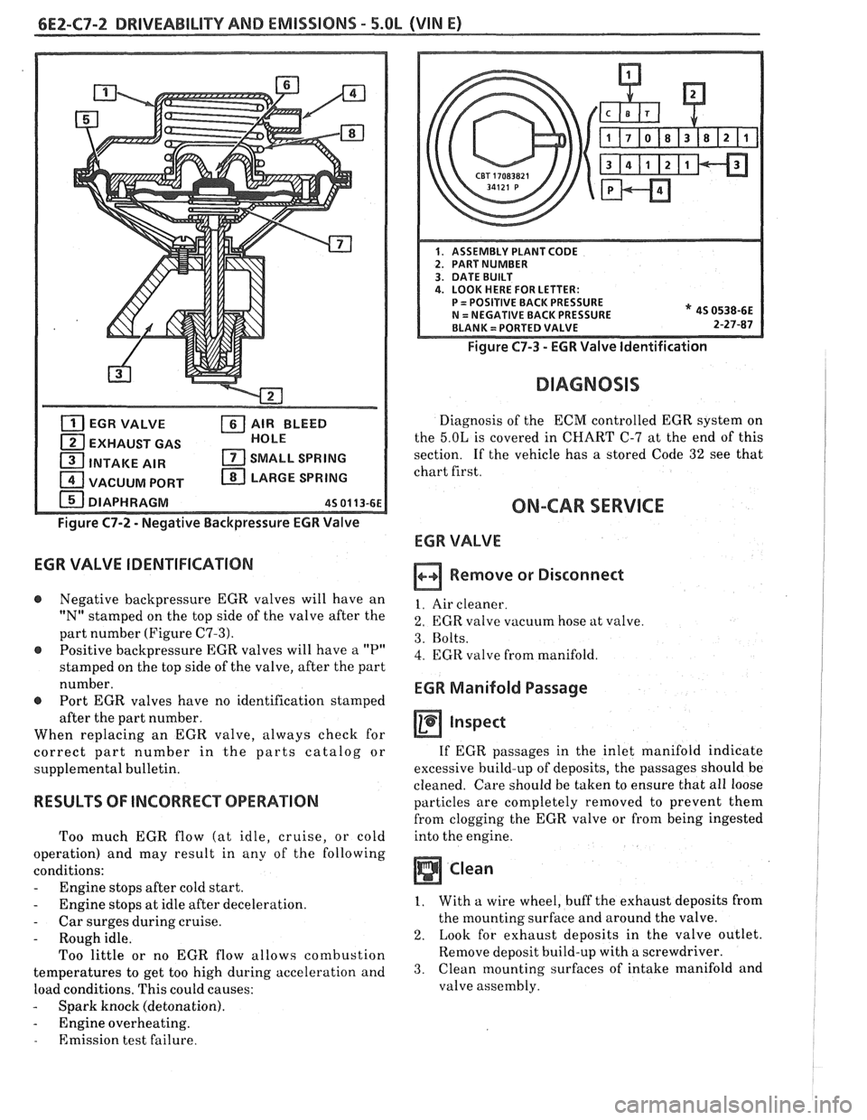
EGR VALVE AIR BLEED
EXHAUST GAS HOLE
1 INTAKE
AIR SMALL SPRING
1 VACUUM PORT LARGE SPRING
DIAPHRAGM
45 01 13-61
Figure C7-2 - Negative Backpressure EGR Valve
EGR VALVE IDENTIFICATION
@ Negative backpressure EGR valves will have an
"N" stamped on the top side of the valve after the
part number (Figure
C7-3).
@ Positive backpressure EGR valves will have a "P"
stamped on the top side of the valve, after the part
number.
@ Port EGR valves have no identification stamped
after the part number.
When replacing an EGR valve, always check for
correct part number in the parts catalog or
supplemental bulletin.
RESULTS OF INCORRECT OPERATION
Too much EGR flow (at idle, cruise, or cold
operation) and may result in any of the following
conditions:
- Engine stops after cold start.
- Engine stops at idle after deceleration.
- Car surges during cruise.
- Rough idle.
Too little or no EGR flow allows combustion
temperatures to get too high during acceleration and
load conditions. This could causes:
- Spark knock (detonation).
- Engine overheating.
- Emission test failure.
Figure C7-3 - EGR Valve Identification
DIAGNOSIS
Diagnosis of the ECM controlled EGR system on
the
5.OL is covered in CHART C-7 at the end of this
section. If the vehicle has
a stored Code 32 see that
chart first.
ON-CAR SERVICE
ECR VALVE
Remove or Disconnect
1. Air cleaner.
2. EGR valve vacuum hose at valve.
3. Bolts.
4. EGR valve from manifold.
EGR Manifold Passage
inspect
If EGR passages in the inlet manifold indicate
excessive build-up of deposits, the passages should be
cleaned. Care should be taken to ensure that all loose
particles are completely removed to prevent them
from clogging the EGR valve or from being ingested
into the engine.
Clean
1. With a wire wheel, buff the exhaust deposits from
the mounting surface and around the valve.
2. Look for exhaust deposits in the valve outlet.
Remove deposit build-up with a screwdriver.
3. Clean mounting surfaces of intake manifold and
valve assembly.
Page 713 of 1825
&E3-B-4 %.8L (VIN S) DRIVEABILITY AND EMISSIONS
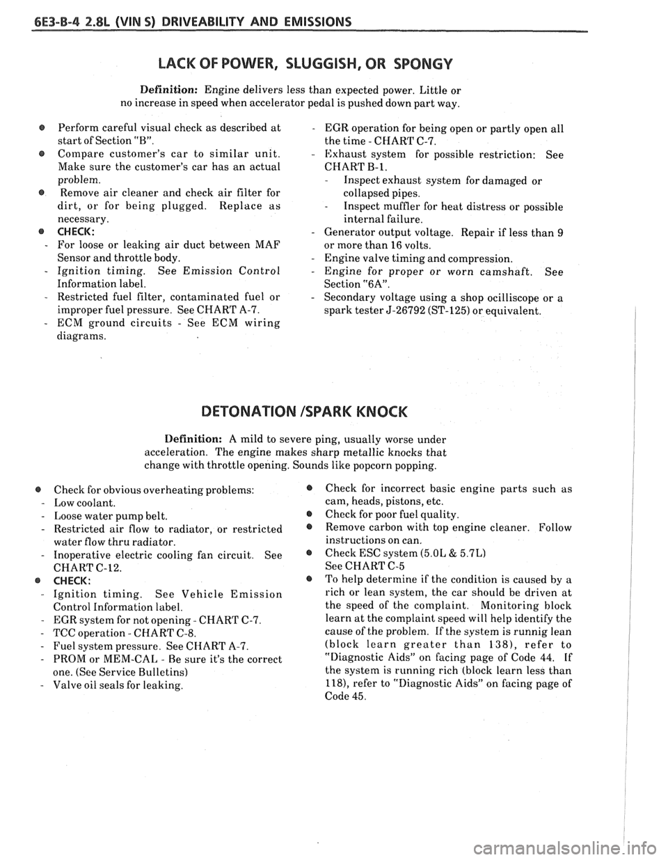
LACK OF POWER, SLUGGISH, OR SPONGY
Definition: Engine delivers less than expected power. Little or
no increase in speed when accelerator pedal is pushed down part way.
Perform careful visual check as described at
- EGR operation for being open or partly open all
start of Section
"B". the time - CHART C-7.
e Compare customer's car to similar unit. - Exhaust system for possible restriction: See
Make sure the customer's car has an actual CHART
B-1,
problem.
@ Remove air cleaner and check air filter for
dirt, or for being plugged. Replace as
necessary.
@ CHECK:
- For loose or leaking air duct between MAF
Sensor and throttle body.
- Ignition timing. See Emission Control
Information label.
- Restricted fuel filter, contaminated fuel or
improper fuel pressure. See CHART A-7.
- ECM ground circuits - See ECM wiring
diagrams.
- Inspect exhaust system for damaged or
collapsed pipes.
- Inspect muffler for heat distress or possible
internal failure.
- Generator output voltage. Repair if less than 9
or more than 16 volts.
- Engine valve timing and compression.
- Engine for proper or worn camshaft. See
Section
"6A".
- Secondary voltage using a shop ocilliscope or a
spark tester
5-26792 (ST-125) or equivalent.
DETONATION ISPARK KNOCK
Definition: A mild to severe ping, usually worse under
acceleration. The engine makes sharp metallic knocks that
change with throttle opening. Sounds like popcorn popping.
@ Check for obvious overheating problems:
- Low coolant.
- Loose water pump belt.
- Restricted air flow to radiator, or restricted
water flow thru radiator.
- Inoperative electric cooling fan circuit. See
CHART C-12.
@ CHECK:
- Ignition timing. See Vehicle Emission
Control Information label.
- EGR system for not opening - CHART C-7.
- TCC operation - CHART C-8.
- Fuel system pressure. See CHART A-7.
- PROM or MEM-CAL - Be sure it's the correct
one. (See Service Bulletins)
- Valve oil seals for leaking.
@ Check for incorrect basic engine parts such as
cam, heads, pistons, etc.
@ Check for poor fuel quality.
@ Remove carbon with top engine cleaner. Follow
instructions on can.
@ Check ESC system (5.OL & 5.7L)
See CHART C-5
o To help determine if the condition is caused by a
rich or lean system, the car should be driven at
the speed of the complaint.
Monitoring block
learn at the complaint speed will help identify the
cause of the problem.
If the system is runnig lean
(block learn greater than
1381, refer to
"Diagnostic Aids" on facing page of Code 44.
If
the system is running rich (block learn less than
l18), refer to "Diagnostic Aids" on facing page of
Code 45.
Page 779 of 1825
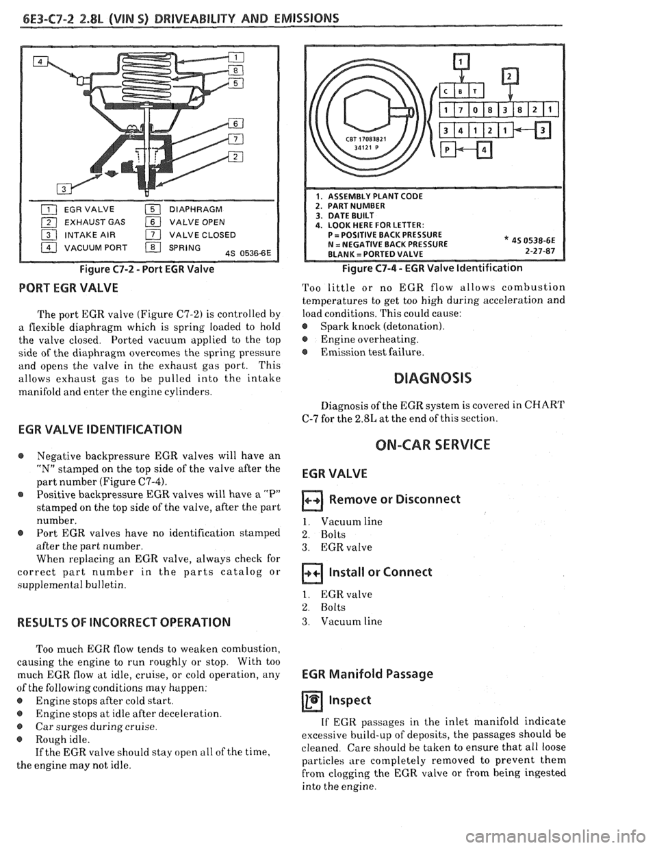
EXHAUST GAS VALVE OPEN
INTAKE AIR
171 VALVE CLOSED
VACUUM PORT
/ SPRING 4s 05366E
Figure C7-2 - Port EGR Valve
PORT EGR VALVE
The port EGR valve (Figure C7-2) is controlled by
a flexible diaphragm which is spring loaded to hold
the valve closed. Ported vacuum applied to the top
side of the diaphragm overcomes the spring pressure
and opens the valve in the exhaust gas port. This
allows exhaust gas to be pulled into the intake
manifold and enter the engine cylinders.
* 45 0538-6E 2-27-87
Figure C7-4 - EGR Valve Identification
Too little or no EGR flow allows combustion
temperatures to get too high during acceleration and
load conditions. This could cause:
@ Spark knock (detonation).
@ Engine overheating.
@ Emission test failure.
Diagnosis of the EGR system is covered in CHART
C-7 for the 2.8L at the end of this section.
EGR VALVE IDENTIFICATION
ON-CAR SERVICE @ Negative backpressure EGR valves will have an
"N" stamped on the top side of the valve after the
part number (Figure
C7-4).
Positive backpressure EGR valves will have a "P"
stamped on the top side of the valve, after the part
number.
@ Port EGR valves have no identification stamped
after the part number.
When replacing an EGR valve, always check for
correct part number in the parts catalog or
supplemental bulletin.
RESULTS OF INCORRECT OPERATION
Too much EGR flow tends to weaken combustion,
causing the engine to run roughly or stop. With too
much EGR flow at idle, cruise, or cold operation, any
of the following conditions may happen:
@ Engine stops after cold start.
e Engine stops at idle after deceleration.
@ Car surges during cruise.
@ Rough idle.
If the EGR valve should stay open
a11 of the time,
the engine may not idle.
EGR VALVE
Remove or Disconnect
1. Vacuum line
2. Bolts
3. EGRvalve
Install or Connect
1. EGR valve
2. Bolts
3. Vacuum line
EGR Manifold Passage
Inspect
If EGR passages in the inlet manifold indicate
excessive build-up of deposits, the passages should be
cleaned. Care should be taken to ensure that all loose
particles are completely removed to prevent them
from clogging the EGR valve or from being ingested
into the engine.
Page 797 of 1825
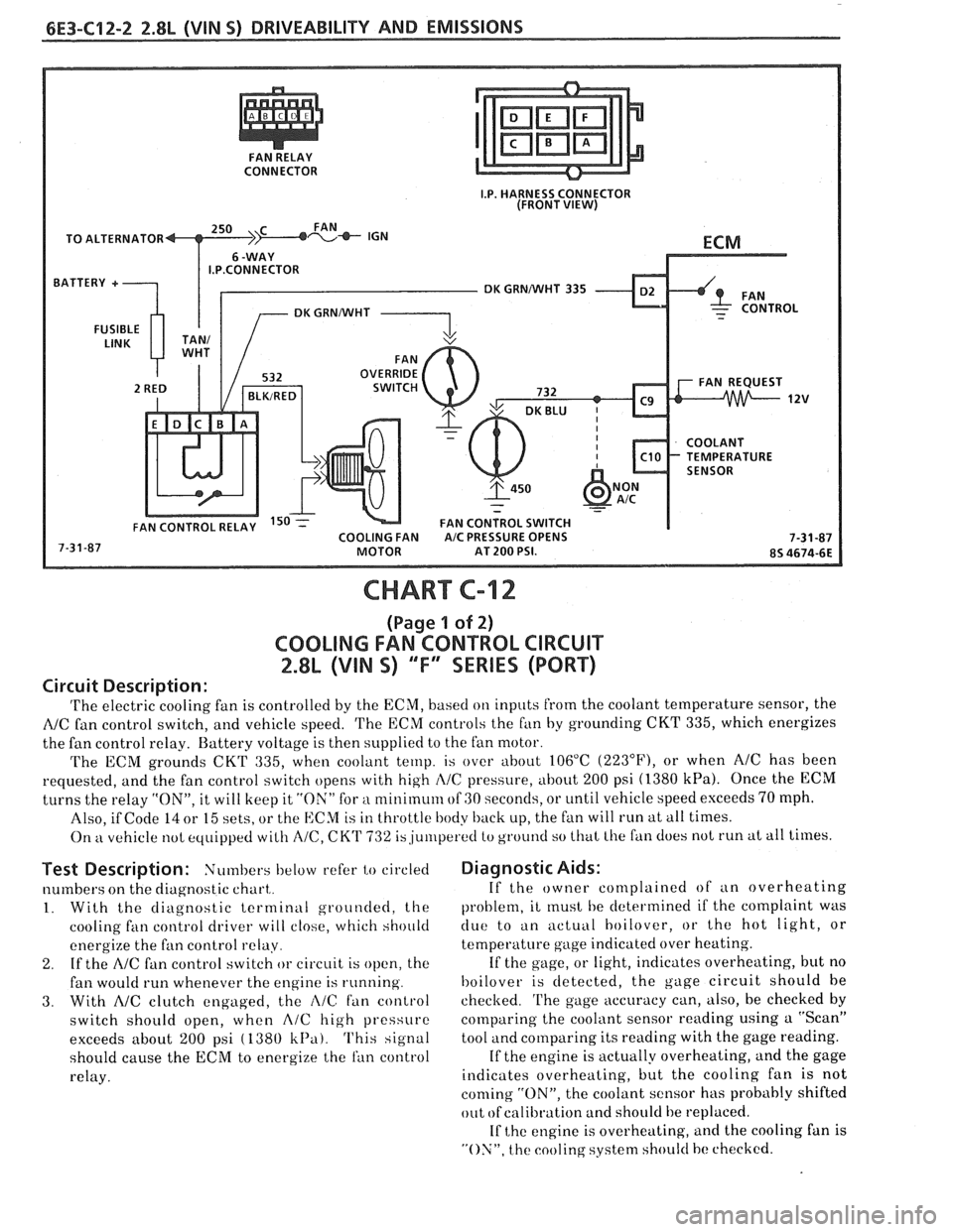
CONNECTOR
TO ALTERNATOR
I.P.CONNECTOR
DK GRNNVHT 335
CHART C-12
(Page 1 of 2)
COOLING FAN CONTROL CIRCUIT
2.8L (VIN S) "F" SERIES (PORT)
Circuit Description:
'I'he electric cooling fan is controlled by the ECM, based on inputs from the coolant temperature sensor, the
NC fan control switch, and vehicle speed. 'I'he ECM controls the f~in by grounding CKT 335, which energizes
the fan control relay. Battery voltage is then supplied to the fan motor.
The ECM grounds
CKT 335, when coolant temp. is over about 106°C (223"F), or when AIC has been
requested, and the fan control switch opens with high
I\/C pressure, about 200 psi (1380 kPa). Once the ECM
turns the relay "ON", it will keep it "ON" for a nlinirnum of GO seconds, or until vehicle speed exceeds 70 mph.
Also, if Code
14 or 15 sets, or the ECM is in throttle body back up, the fan will run at all times.
On
kt vehicle not equipped with A/C, CK'I' 732 is,ju~rlperetl to ground so that Lhe fan does not run at all times.
Test Description: Numbers below refer to circled
numbers on the diagnostic chart,.
1. With the diagnostic terminal grounded, the
cooling
fan control driver will close, which should
energize the fan control
relay.
2. If the A/C fan control switch or circuit is open, the
fan would run whenever the engine is running.
3. With AIC clutch engaged, the i\lC fan control
switch should open, when
A/C high pressure
exceeds about
200 psi ( 1380 k13a). This signal
should cause the
ECM to energize the ran control
relay.
Diagnostic Aids:
If the owner complained of an overheating
problem, it
rnust he determined if the complaint was
clue to an actuill hoilover, or the hot light, or
temperature gage indicated over heating.
If the gage, or light, indicates overheating, but no
hoilover is detected, the gage circuit should he
checked.
'I'he gage accuracy can, also, be checked by
comparing the coolant sensor reading using a "Scan"
tool and comparing its reading with the gage reading.
If the engine is actually overheating, and the gage
indicates overheating, but the cooling fan is not
coming "ON", the coolant sensor has probably shifted
out
ofcalibration and should be replaced.
If
the engine is overheating, and the cooling fan is
"ON", the cooling system should hc checked.
Page 805 of 1825
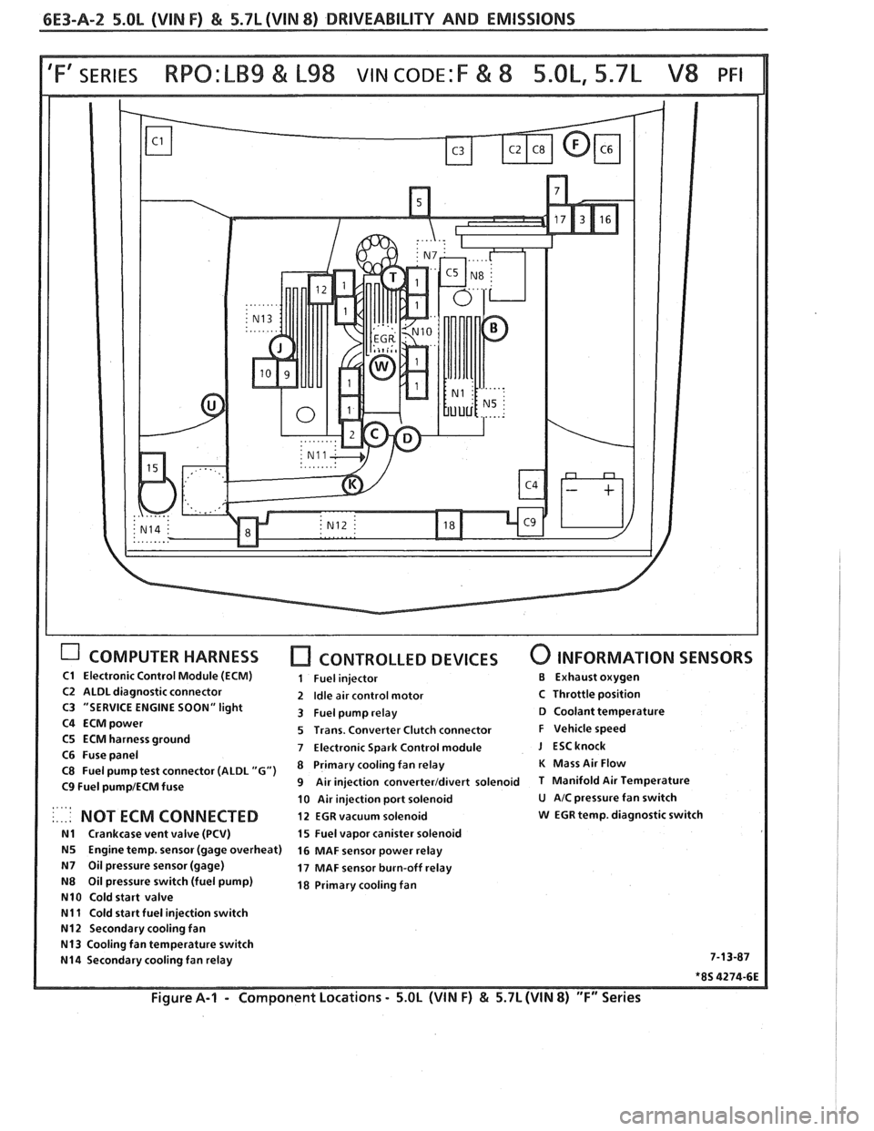
6E3-A-2 5.OL (VIN F) & 5.7L(VIN 8) DRIVEABILITY AND EMISSIONS
COMPUTER HARNESS [7 CONTROLLED DEVICES 0 INFORMATION SENSORS
C1 Electronic Control Module (ECM) 1 Fuel injector €3 Exhaust oxygen
C2 ALDL diagnostic connector 2 Idle air control motor C Throttle position
C3 "SERVICE ENGINE SOON" light
3 Fuel pump relay D Coolant temperature
C4
ECMpower 5 Trans. Converter Clutch connector F Vehicle speed
C5 ECM harness ground
7 Electronic Spark Control module J ESCknock C6 Fuse panel
C8 Fuel pump test connector (ALDL "G") Primary fan relay K Mass Air Flow
C9 Fuel pump1ECM fuse 9 Air injection converterldivert solenoid T Manifold Air Temperature
10 Air injection port solenoid
U AIC pressure fan switch . ., .. .. NOT ECM CONNECTED 12 EGR vacuum solenoid w EGR temp. diagnostic switch
N1 Crankcase vent valve (PCV) 15 Fuel vapor canister solenoid
N5 Engine temp. sensor (gage overheat)
16 MAF sensor power relay
N7 Oil pressure sensor (gage) 17 MAF sensor burn-off relay
N8 Oil pressure switch (fuel pump) 18 Primary cooling fan
N10 Cold start valve
N11 Cold start fuel injection switch
N12 Secondary cooling fan
N13 Cooling fan temperature switch
N14 Secondary cooling fan relay 7-13-87
*8S 4274-6E
Figure A-I - Component
Locations - 5.OL (WIN F) & 5.7L (WIN 8) "F" Series