1988 PONTIAC FIERO relay
[x] Cancel search: relayPage 892 of 1825
DRIVEABILITY AND EMISSIONS 5.OL (VIN F) & 5.7L (VIN 8) 6E3-C2-5
Fuel Pump Electrical Circuit
When the ignition is first turned "ON", without
the engine running, the ECM will turn the fuel pump
relay "ON" for two seconds.
This builds up the fuel
pressure quickly. If the engine is not started within
two seconds, the ECM will shut the fuel pump "OFF"
and wait until the engine is cranking. As soon as the
engine is cranked, the ECM will turn the relay "ON"
and run the fuel pump.
As
a backup system to the fuel pump relay, the
fuel pump can also be turned "ON" by the oil pressure
switch. The oil pressure switch is a normally open
switch which closes when oil pressure reaches about
28
kPa (4 psi). If the fuel pump relay fails, the oil
pressure switch will close, and run the fuel pump.
An inoperative fuel pump relay can result in long
cranking times, particularly if the engine is cold but
should result in
a Code 54.
An inoperative fuel pump would cause a no start
condition. A fuel pump which does not provide enough
pressure can result in poor performance.
DIAGNOSIS
FUEL CONTROL SYSTEM
Some failures of this system will result in an
"Engine Cranks But Won't Run". If
this condition
exists see CHART A-3. This chart will determine if
the problem is caused by the ignition system, ECM, or
fuel pump circuit. If
it's determined to be a fuel
problem CHART A-7 will be used. This includes the
injectors, pressure regulator, fuel pump, and fuel
pump relay. The fuel system wiring schematic is
covered on the facing page of Code CHART 54.
If a malfunction occurs in the fuel control system,
it usually results in either a rich or
a lean exhaust
condition. This condition is sensed by the oxygen
sensor and the ECM will change the fuel calculation
(injector pulse width) based on the
O2 sensor reading.
The change
made to the fuel calculation will be
indicated by a change in the block learn values, which
can be monitored by a "Scan" tool.
The normal block
learn values are around 128, and if the
O2 sensor is
sensing a lean condition, the EC
M will add fuel which
will result in a block learn value above 128.
If the O2
sensor is sensing a rich exhaust the ECM will reduce
fuel to the engine and this will result in block learn
values below 128. Some variations in block
learn
values are normal because all engines are not exactly
the same. However, if the block learn values are
+ 10
counts from 128 a system problem exists. If the block
learn values are greater than 138 see Code 44, for
items which can cause a lean system.
If the block learn values are less than 118 see Code
45 for items which can cause the system to run rich. If
a driveability symptom exists, refer to the
particular symptom in Section
"B" for additional
items to check.
IDLE AIR CONTROL VALVE
AUScan" tool will read IAC position in steps (counts).
"0" steps indicates the ECM is commanding the IAC to
be driven all the way in, to a fully seated position, and
this is usually caused by a vacuum leak. The higher
the number of counts the more air being allowed to
pass the IAC valve. CHART C-2C can be used to
diagnosis the IAC valve. Also refer to "Rough,
Unstable, or Incorrect Idle, Stalling" in symptoms,
Section "B" for other possibilities for the cause
of idle
problems.
FUEL SYSTEM PRESSURE TEST
A fuel system pressure test is part of several of the
diagnostic charts and symptom checks. To perform
this test, use the procedure in CHART A-7.
ON-CAR SERVICE
PORT FUEL INJECTION COMPONENTS
CAUTION:
Before servicing an injector, fuel
rail, or pressure regulator,
it is
necessary to relieve the pressure in
the fuel system, to minimize the
risk of fire and personal injury.
(See "Fuel Pressure Relief
Procedure" below). To reduce the
chance of personal injury, cover
the fuel line with
a shop cloth to
collect the fuel, and then place the
cloth in an approved container.
FUEL PRESSURE RELIEF PROCEDURE
1. Connect fuel gage J 34730-1 or equivalent to fuel
pressure valve. Wrap a shop towel around fitting
while connecting gage to avoid spillage.
2. Install bleed hose into an approved container and
open valve to bleed system pressure.
Plenum
(Figure
C2-6)
Remove or Disconnect
1. Negative battery cable.
2. Throttle, 'F.V., and cruise control cable.
3. Cable retaining bracket.
4.
'I'hrottle body retaining bolts (4).
5. 'L'l'S and IAC valve electrical connectors.
6. Vacuum hoses.
Page 903 of 1825
6E3-CZ-16 5.OL (VIN F) & 5.7L(VIN 8) DRIVEABILITY AND EMISSIONS
Tighten
- @ Screw assemblies to 3.0 Nem (27.0 in. lbs.).
4. IAC valve assembly (70). (See "Idle Air Control
Valve and Gasket" instructions).
NOTICE: Before installing the IAC valve assembly,
the position of its pintle
MUST be checked.
If pintle is extended too far, damage to the
assembly may occur. (See
"Idle Air
Control Valve and Gasket" instructions.)
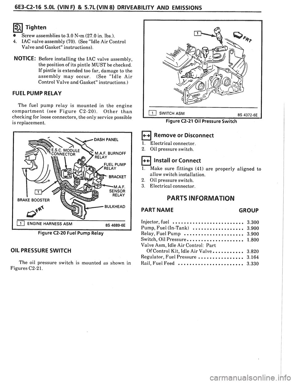
FUEL PUMP RELAY
The fuel pump relay is mounted in the engine
compartment (see Figure
C2-20). Other than
checking for loose connectors, the only service possible
is replacement.
BRAKE BOOSTER
Figure C2-20 Fuel Pump Relay
OIL PRESSURE SWITCH
The oil pressure switch is mounted as shown in
Figures C2-2
1.
Figure C2-21 Oil Pressure Switch
a Remove or Disconnect
I. Electrical connector.
2. Oil pressure switch.
Install or Connect
1. Make sure fittings (41) are properly aligned to
allow switch installation.
2. Oil pressure switch.
3. Electrical connector.
PARTS INFORMATION
PART NAME GROUP
Injector, fuel ......................... 3.300
Pump, Fuel (In-Tank)
.................. 3.900
Relay, Fuel Pump
..................... 3.900
Switch, Oil Pressure,
................... 1.800
Valve Asm, Idle Air Control: Part
Of Control Kit, Idle Air Valve. .......... 3.820
Regulator, Fuel Pressure
................ 3.164
Itail, Fuel Feed ....................... 3.330
Page 950 of 1825
DRlVEABlLlPV AND EMISSIONS 5.OL (VIN F) & 5.7L (VIN 8) 6E3-C"1-1
SECTION Cl2
COOLING FAN CONTROL
CONTENTS
GENERAL DESCRIPTION ................ C12-I DIAGNOSIS ......................... C1Z-1
OPERATION ..................... .. C12-1 ON-CARSERVICE ..................... C12-1
PARTS INFORMATION ................. C12-1
GENERAL DESCRIPIION DlAGNODlS
The fan is used for engine and AIC condenser
cooling but the fan only operates under certain
conditions. The
following charts will diagnose the ECM
controlled cooling fan.
Use
Sect.ion "8A" to diagnose the secondary
cooling fan.
OPERATION
ON-CAR SERVICE
The electric cooling fan on this engine is controlled
by the ECM. The ECM will ground the cooling fan
relay, which turns "ON" the fan, when the following
conditions are met.
@ Coolant temperature sensor signal indicating a
temperature greater than 106°C
(222°F).
@ AIC head pressure greater than 233 psi and
vehicle speed less than 40 mph.
When the cooling fan is turned "ON", it will stay
"ON" for a minimum time of 15 seconds. Cooling
system component replacement can be
found in Section
"6B".
PARTS INFORMATION
PART NAME GROUP
......................... Fan, Engine 1.055
......................... Motor, Fan. 1.055
.................... Relay, Engine Fan 1.055
Page 951 of 1825
6E3-C12-2 5.OL (VIN F) & 5.7b (VIN 8) DRIVEABILITY AND EMISSIONS
FAN CONTROL
RELAY CONN.
DK GRNNVHT 335
TEMPERATURE
SENSOR SIGNAL.
TURNS ON PRIMARY
FAN AT
223OF (1 06'C)
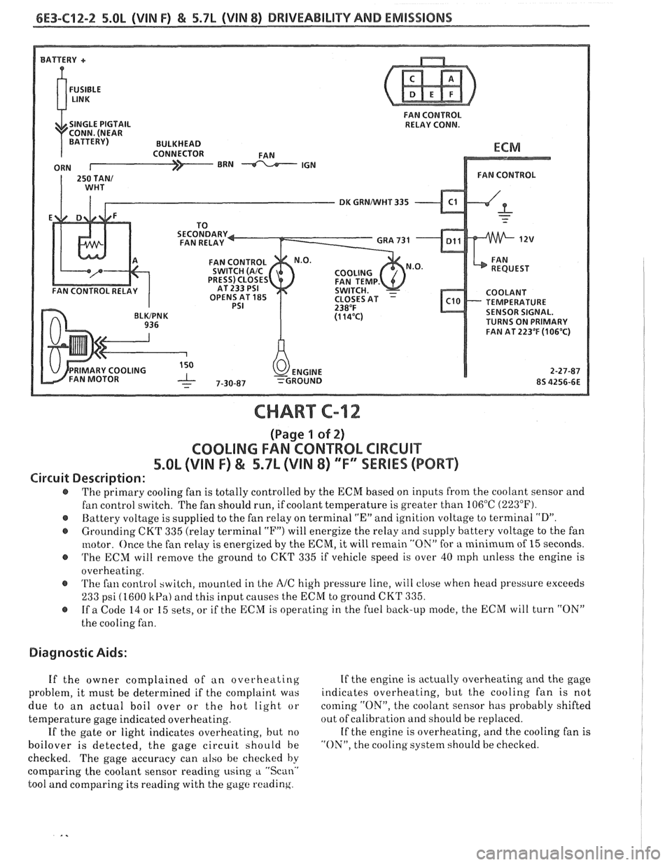
CHART C-12
(Page 1 of 2)
COOLING FAN CONTROL CIRCUIT
5.8L (VIN F) & 5.7L (VIN 8) "F" SSERlES (PORT)
Circuit Description:
The primary cooling fan is totally controlled by the ECM based on inputs from the coolant sensor and
fan control switch. The fan should run, if coolant temperature is greater than 106°C
(223°F).
@ Battery voltage is supplied to the fan relay on terminal "En and ignition voltage to terminal "D".
@ Grounding CKT 335 (relay terminal "F") will energize the relay and supply battery voltage to the fan
motor. Once the fan relay is energized by the
ECM, it will remain "ON" for a minimum of 15 seconds.
@ 'I'he ECM will remove the ground to CKT 335 if vehicle speed is over 40 rnph unless the engine is
overheating.
@ 'I'he fan control switch, mounted in Lhe AIC high pressure line, will close when head pressure exceeds
233 psi (1600 kPa) and this input causes the ECM to ground CKT 335.
@ If a Code 14 or 15 sets, or if the ECM is operating in the fuel back-up mode, the ECM will turn "ON"
the cooling fan.
Diagnostic Aids:
If the owner complained of an overheating If
the engine is actually overheating and the gage
problem, it must be determined if the complaint was indicates
overheating, but
t,he cooling fan is not
due to an actual boil over or the hot light or coming
"ON", the
coolant sensor has probably shifted
temperature gage indicated overheating. out
of calibration and should be replaced.
If the gate or light indicates overheating, but no If
the engine is overheating, and the cooling fan is
boilover is detected, the gage circuit should be "ON", the cooling system should be checked.
checked. The gage accuracy can also be checked by
comparing the coolant sensor reading using
a "Scan.'
tool and comparing its reading with the gage reading.
Page 953 of 1825
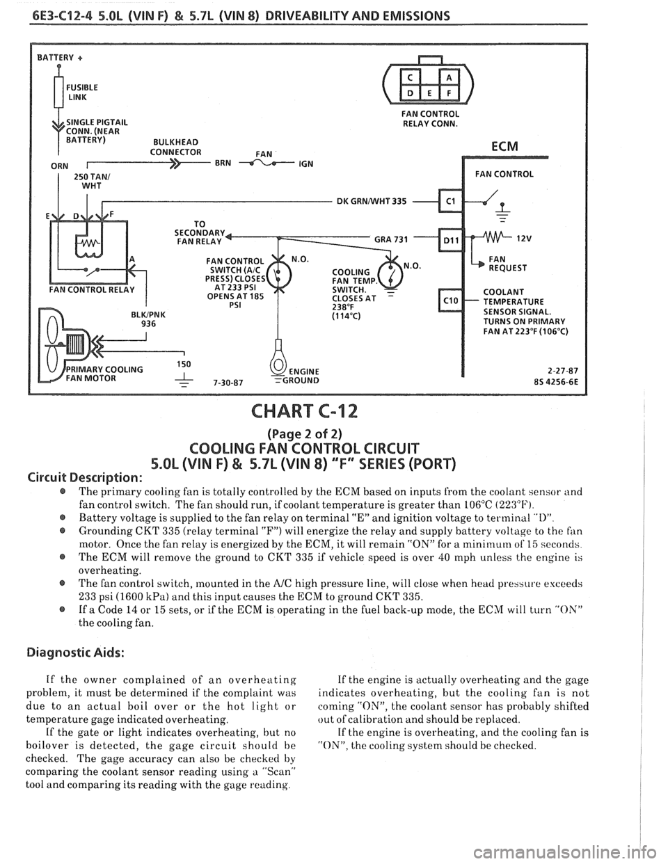
6E3-C12-4 5.8L (VIN F) & 5.7L (VIN 8) DRIVEABILITY AND EMISSIONS
FAN CONTROL
SINGLE PIGTAIL RELAY CONN.
DK GRNNVHT 335
OPENS AT
185 TEMPERATURE SENSOR SIGNAL.
TURNS ON PRIMARY
FAN AT 223°F
(106°C)
CHART C-12
(Page 2 of 2)
COOLING FAN CONTROL CIRCUIT
5.OL (VIN F) & 5.7L (VIN 8) ""FYSERlES (PORT)
Circuit Description:
@ The primary cooling fan is totally controlled by the ECM based on inputs from the coolant sensor and
fan control switch. The fan should run, if coolant temperature is greater than 106°C
(223°F).
@ Battery voltage is supplied to the fan relay on terminal "En and ignition voltage to terminal "I)"
@ Grounding CKT 335 (relay terminal "F") will energize the relay and supply battery voltage to the fan
motor. Once the fan relay is energized by the ECM, it will remain "ON" for a mini~nuln of 15 seconds
@ The ECM will remove the ground to CKT 335 if vehicle speed is over 40 mph unless the engine is
overheating.
@ The fan control switch, mounted in the A/C high pressure line, will close when head pressure exceeds
233 psi (1600 kPa) and this input causes the ECM to ground CKT 335.
@ If a Code 14 or 15 sets, or if the ECM is operating in the fuel back-up mode, the ECM will turn "OX"
the cooling fan.
Diagnostic Aids:
If the owner complained of an overheating If the engine is actually overheating and the gage
problem, it must be determined if the complaint was indicates overheating, but the cooling fan is not
due to an actual boil over or the hot light or coming
"ON", the coolant sensor has probably shifted
temperature gage indicated overheating. out
of calibration and should be replaced.
If the gate or light indicates overheating, but no If the engine is overheating, and the cooling fan is
boilover is detected, the gage circuit should be "ON". the cooling system should be checked.
checked. The gage accuracy can also be checked
by
comparing the coolant sensor reading using a "Scan"
tool and comparing its reading with the gage reading.
Page 958 of 1825
INDEX
SECTION PAGE
.................... Acceleration Mode C2-2
A/C On Signal
General Description
................. C1-4
......................... Diagnosis C1-5
Air Injection Check Valve
............... C6-4
Air Injection Control (Pedes) Valve
........ C6-1
Air Injection Reaction (A.I.R.) System
General Description
................. C6-1
......................... Diagnosis C6-2
Air Management Check (Pedes)
.......... C6-6
AirPump ........................... C6-2
........................... Service C6-3
...................... ALDL Connector A- 12
Automatic Transmission
Overdrive Switch Adjustment
.......... C8-3
Automatic Transmission Converter Clutch
(TCC) Electrical Diagnosis
.............. C8-6
Backfire
............................ B-5
Battery Voltage Correction Mode
......... C2-3
....................... Before Starting B-I
........................ Burnoff Relay C1-8
......................... Calpac Error 8-60
........................ Canister Hose C3-3
Canister Purge Solenoid
................ C3-3
Chart
A-1 :
.......... No Service Engine Soon Light A-1
0
Chart
A-2:
No ALDL Data. Or Won't Flash Code 12.
Or Service Engine Soon Light On Steady
. . A-1 2
Chart A-3:
Engine Cranks But Won't Run
.......... A-14
Chart A-7:
................ Fuel System Diagnosis A- 18
Chart A-9:
........... Cold Start Valve Circuit Test A-22
Chart
B-1:
Restricted Exhaust System Check ........ B-8
Chart
C-1A:
......... ParkINeutral Switch Diagnosis C1-10
Chart C-2A:
................. Injector Balance Test C2-18
Chart C-2C:
Idle Air Control (IAC) System Check ...... C2-20
SECTION PACE
Chart C-3:
........... Canister Purge Valve Check C3-4
Chart C-4:
................ Ignition System Check C4-4
Chart
6-5:
.......... Electronic Spark Control (ESC) C5-4
Chart C-6:
.............. Air Management Check C6-6
Chart C-7:
Exhaust Gas Recirculation
............. C7-4
Chart
C-8A:
Automatic Transmission Converter Clutch
............................. (TCC) C8-6
Chart C-8B:
Manual Transmission With Overdrive
.... C8-10
Chart C- 12
:
................. Cooling Fan Control C12-2
............................ Chuggle B-3
................... Clear Flood Mode.. C2-2
......................... Closed Loop C2-1
Code12
............................ C4-1
Code13
............................ A-24
Code14
............................ A-26
Code15
............................ A-28
Code21
............................ A-30
Code22
............................ A-32
Code23
............................ A-34
Code24
............................ A-36
Code25
............................ A-38
Code32
............................ A-40
Code33
............................ A-42
Code34
............................ A-44
Code36
............................ A-46
Code41
............................ A-48
Code42
............................ A-50 C4-2
Code43
............................ A-52
Code44
............................ A-54
Code45
............................ A-56
Code46
............................ A-58
Code54
............................ A-60
...................... Codes 51.52. 53 A-62
Cold Start Tube And Valve Assembly
...... C2-7
Cold Start Fuel
lnjection Sw~tch
.................. General Description C2-11
......................... Diagnosis A-22
.................. Component Location A-2
Coolant Temperature Sensor
.................. General Description C1-2
.......................... Diagnosis C1-4
A-26
........................... Service C1-7
Page 959 of 1825
INDEX
SECTION PAGE
Cooling Fan Control
................. General Description C12-1
........................ Diagnosis C12-2
........................... Cuts Out B-5
................... Cylinder Select Error A-48
.................... Deceleration Mode C2-3
......................... Detonation B-4
..................... Dieseling. Run On B-6
............. Distributor Reference Signal C1-4
...................... ECM Terminals A-7
.................. ECM Wiring Diagram A3-A6
EGR Control Valve
................. General Description C7-1
................. Valve Identification C7-2
................... Diagnosis. Service C7-2
A-40
.................. EGR Control Solenoid C7-3
......................... EGR Check C7-4
Electronic Control Module
................. General Description C1-1
......................... Diagnosis C1-4
............................ Service C1-5
..................... Function Check C1-7
Electronic Spark Control (ESC) System
................. General Description C5-1
................... Diagnosis. Service C5-4
Electronic Spark Timing EST
............. A-50
A-52
Engine Cranks But Won't Run
............ A-14
........................ Engine Knock C5-4
.......................... ESC Module C5-2
.......................... ESC Sensor C5-1
.................... ESC System Check C5-4
................... ESTllgnition System C4-1
Evaporative Emission Control System
................. General Description C3-1
.......................... Diagnosis C3-2
Exhaust Emissions Excessive (Odors)
....... B-7
Exhaust Gas Recirculation (EGR) System
.... C7-1
Exhaust System Check Restricted
......... B-8
Fuel Control System
................. General Description C2- 1
......................... Diagnosis C2-5
..................... Fuel Cutoff Mode C2-3
SECTION PAGE
Fuel Injectors ........................
Fuel Pressure Connection Assy ............
Fuel Pressure Relief Procedure ...........
Fuel Pump Electrical Circuit .............
Fuel Pump Relay ......................
Fuel Rail
General Description
.................
........................... Service
Fuel System Diagnosis
..................
Fuel System Pressure Test ...............
Fuel Tank Pressure Control Valve .........
.......................... Hard Start B-2
.......... HE1 High Energy Ignition System C4-1
.......................... Hesitation
B-3
............ Idle Air Control System Check C2-20
.................. Idle Air
Control Valve C2-4
......................... Diagnosis C2-5
.................... Ignition System EST C4-1
........ Ignition System Check Integral Coil C4-4
........................ Incorrect Idle B-6
.................. Information Sensors C1.2. 9
.................. Injector
Balance Test C2-18
........................ lntermittents B-2
........................ Knock Sensor C1-3
........................ Lack Of Power B-4
......... Light. Manual Transmission Shift C8-6
.............. Light. Service Engine Soon A-10
MAF Sensor
.................. General Description C1-2
.......................... Diagnosis C1-5
A.42.44. 46
............................ Service C1-8
... Manual Transmission Electrical Diagnosis C8-10
MAT Sensor
.................. General Description C1-2
......................... Diagnosis C1-5
A.34. 38
Page 966 of 1825
DRIVEABILITY AND EMISSIONS - FUEL INJECTION 6E-5
TERMINAL IDENTIFICATION
GROUND SERIALDATA
(SEE SPECIAL TOOLS)
DIAGNOSTIC TERMINAL
I.I.R. (IF USED) T.C.C. (IF USED)
SERVICE
ENGINE FUEL PUMP (IF USED)
SOON LAMP- IF USED
SERIAL DATA (IF USED) 3-29-86 *6S 2615-6E (SEE SPECIAL TOOLS)
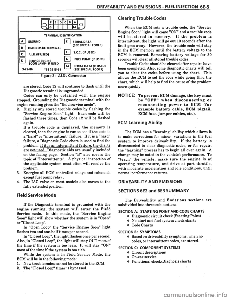
Figure 2 - ALDL Connector
are stored, Code 12 will continue to flash until the
Diagnostic terminal is ungrounded.
Codes can only be obtained with the engine
stopped. Grounding the Diagnostic terminal with the
engine running gives the "field service mode".
2. Display any stored trouble codes by flashing the
"Service Engine Soon" light. Each code will be
flashed three times, then Code
12 will be flashed
again.
If a trouble code is displayed, the memory is
cleared, then the engine is run to see
if the code is
a "hard" or "intermittent" failure. If it is a "hard"
failure, a Diagnostic Code chart is used to find the
problem. If it is an intermittent failure, the charts
are not used. Diagnostic aids are usually included
on the facing page. Section
"B" also covers the
topic of "Intermittents".
A physical inspection of
the applicable system most often will resolve the
problem.
3. Energize all ECM controlled relays and solenoids
except fuel pump relay
.
4. The IAC valve on most models also moves to the
fully extended position.
Field Service Mode
If the Diagnostic terminal is grounded with the
engine running, the system will enter the Field
Service mode. In this mode, the "Service Engine
Soon" light will show whether the system is in "Open"
or
"Closed Loop".
In "Open Loop" the "Service Engine Soon" light
flashes two and one-half times per second.
In "Closed Loop", the light flashes once per second:
Also, in "Closed Loop", the light will stay OUT most of
the time
if the system is too lean. It will stay "ON"
most of the time if the system is too rich.
While the system is in Field Service Mode, the
ECM will be in the following mode:
1. New trouble codes cannot be stored in the ECM.
2. The "Closed Loop" timer is bypassed.
Clearing Trouble Codes
When the ECM sets a trouble code, the "Service
Engine Soon" light will come "ON" and a trouble code
will be stored in memory. If the problem is
intermittent, the light will go out
10 seconds after the
fault goes away. However, the trouble code will stay
in the ECM memory until the battery voltage to the
ECM is removed. Removing battery voltage for
30
seconds will clear all stored trouble codes.
Trouble Codes should be cleared after repairs have
been completed. Also, some diagnostic charts will tell
you to clear the codes before using the chart. This
allows the ECM to set the code while going thru the
chart, which will help to find the cause of the problem
more quickly.
NOTICE: To prevent ECM damage, the key must
be
"OFFn when disconnecting or
reconnecting power to
ECM (for
example battery cable,
ECM pigtail,
ECM fuse, jumper cables, etc.).
ECM Learning Ability
The ECM has a "learning" ability which allows it
to make corrections for minor variations in the fuel
system to improve driveability. If the battery is
disconnected to clear diagnostic codes, or for repair,
the "learning" process has to begin all over again.
A
change may be noted in the vehicle's performance. To
"teach" the vehicle, make sure the engine is at
operating temperature, and drive at part throttle,
with moderate acceleration and idle conditions, until
normal performance returns.
DRIVEABILITY AND EMISSIONS
SECTIONS
6E2 and 6E3 SUMMARY
The Driveability and Emissions sections are
subdivided into three sub-sections:
SECTION A: STARTING POINT AND CODE CHARTS
@ Diagnostic circuit check (Starting Point)
@ No-start and fuel system check charts
@ Code Charts
SECTION B: SYMPTOMS
e Based on driveability symptoms, when no
codes, or intermittent codes, are stored.
SECTION C: COMPONENT SYSTEMS
@ Circuit descriptions
@ On-car service
@ Functional checWDiagnosis charts