1988 PONTIAC FIERO relay
[x] Cancel search: relayPage 813 of 1825
TO MAF SENSOR
POWER & BURN-OFF
RELAY, OIL PRESS. SW.
.....-
439 PNKIBLK
419 BRNNVHT
SERIAL DATA
451 WHTIBLK
450
BLWHT
ALDL CONNECTOR
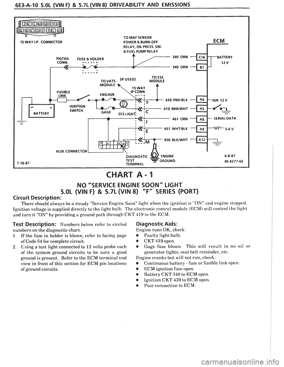
CHART A - 1
NO "'SERVICE ENGINE SOON" LIGHT
5.OL (VIN F) & 5.7L (VIN 8) "F'XSEBIE'S (PORT)
Circuit Description:
There should always be a steady "Service Engine Soon" light when the ignition is "ON" and engine stoppccl.
Ignition voltage is supplied directly to the light bulb. The electronic control module (ECM) will control the light
and turn it
"ON" by providing a ground path through CKT 419 to the ECM.
Test Description: Numbers below refer to circled
numbers on the diagnostic chart.
1. If the fuse in holder is blown, refer to facing page
of Code
54 for complete circuit.
2. Using a test light connected to 12 volts probe each
of the system ground circuits to be sure a good
ground is present. Refer to the ECM terminal end
view in front of this section for ECM pin locations
of ground circuits.
Diagnostic Aids:
Engine runs OK, check:
r Faulty light bulb.
@ CKrI' 419 open.
@ Gage fuse blown. This
will result in no oil or
generator lights, seat belt reminder, etc.
Engine cranks but will not run, check:
r Continuous battery - fuse or fusible link open.
@ ECM ignition fuse open.
r Battery CKT 340 to ECM open.
@ Ignition CKT 439 to ECM open.
@ Poor connection to ECM.
Page 824 of 1825
DRIVEABILITY AND EMISSIONS 5.0L (VIN F) & 5.7L (VIN 8) 6E3-A-21
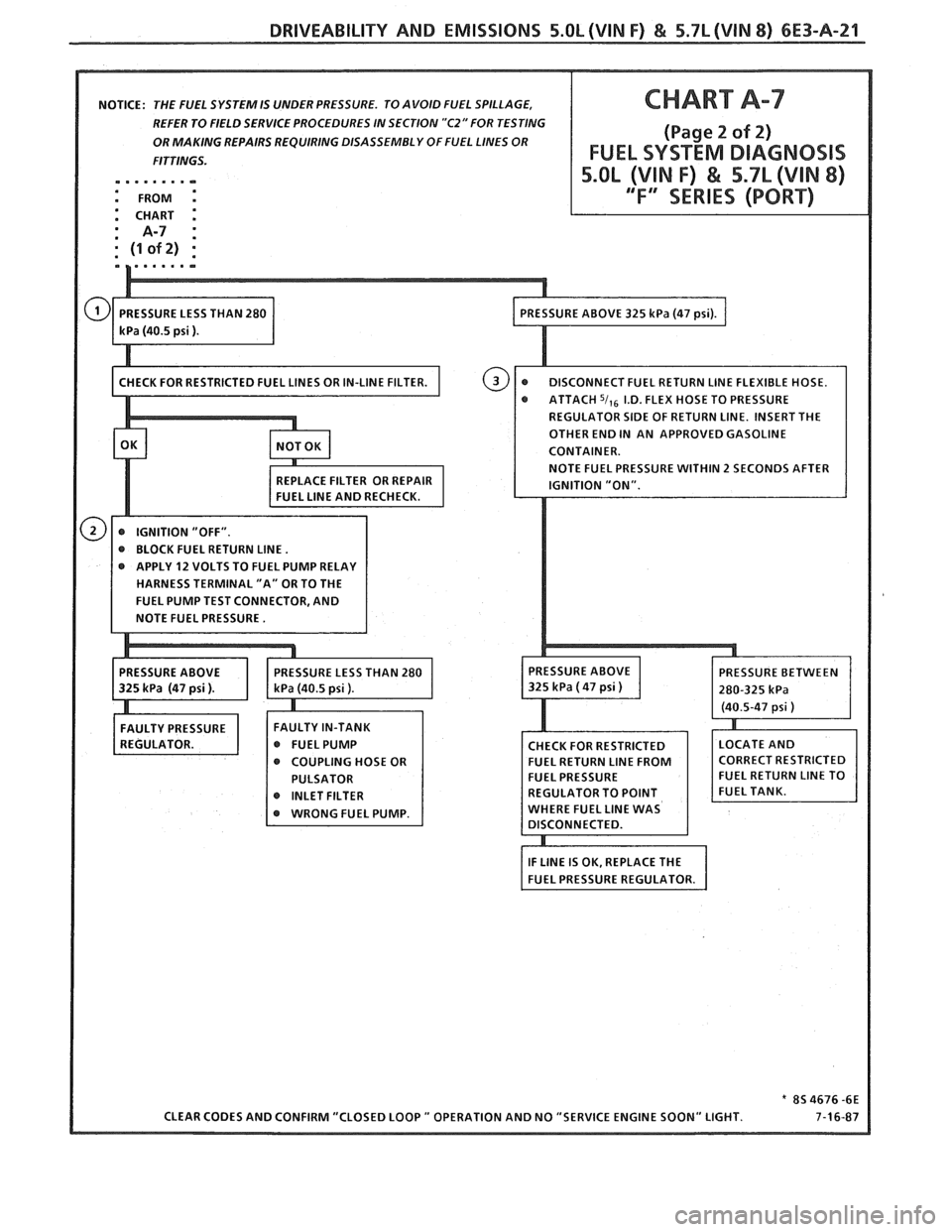
NOTICE: THE FUEL SYSTEM IS UNDER PRESSURE. TO AVOID FUEL SPILLAGE,
REFER TO FIELD SERVICE PROCEDURES IN SECTION
"C2" FOR TESTING
OR MAKING REPAIRS REQUIRING DISASSEMBLY OF FUEL LINES OR
.m ...... -
SE TO PRESSURE
@ BLOCK FUEL RETURN LINE.
@ APPLY 12 VOLTS TO FUEL PUMP RELAY
HARNESS TERMINAL "A" OR TO THE
FAULTY IN-TANK
r FUELPUMP
@ COUPLING HOSE OR
Page 845 of 1825
6E3-A-42 S.OL (VIN F) & 5.7L (VIN 8) DRIVEABILITY AND EMISSIONS
SYSTEM GND
SYSTEM GND
SYSTEM GND
ANALOG GND
BURN-OFF CONTROL CKT
-
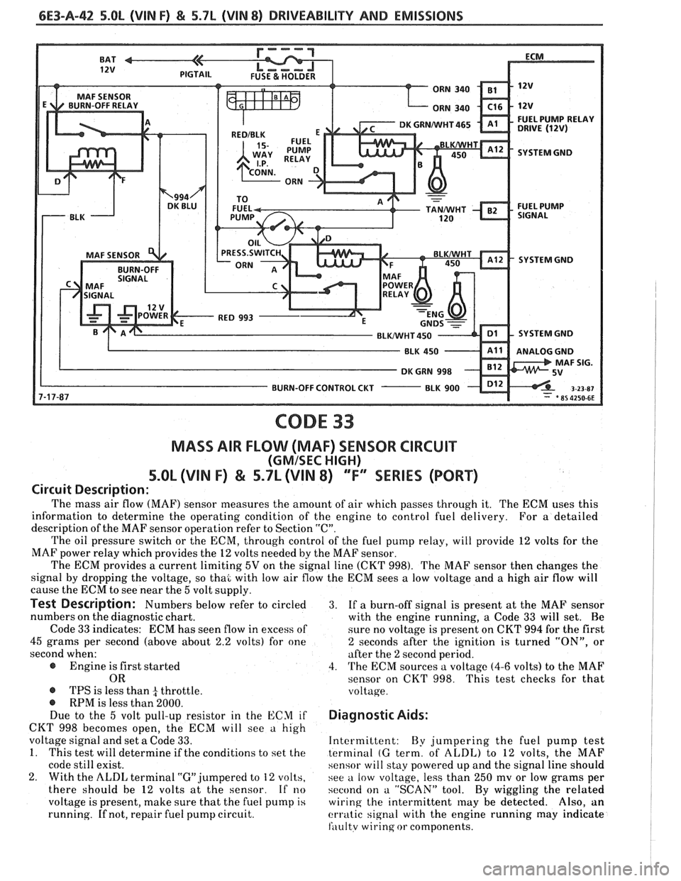
CODE 33
MASS AIR FLOW (MAF) SENSOR CIRCUIT
(GMISEC HIGH)
5.OL (VIN F) & 5.7L (VIN 8) ""FY"IES (PORT)
Circuit Description:
The mass air flow (MAF) sensor measures the amount of air which passes through it. The ECM uses this
information to determine the operating condition of the engine to control fuel delivery.
For
a detailed
description of the MAF sensor operation refer to Section
"C".
The oil pressure switch or the ECM, through control of the fuel pump relay, will provide 12 volts for the
MAF power relay which provides the
12 volts needed by the MAF sensor.
The ECM provides
a current limiting 5V on the signal line (CKT 998). The MAF sensor then changes the
signal by dropping the voltage, so thai with low air flow the ECM sees
a low voltage and a high air flow will
cause the ECM to see near the
5 volt supply.
Test Description: Numbers below refer to circled 3. If a burn-off signal is present at the MAF sensor
numbers on the diagnostic chart.
with the engine running, a Code
33 will set. Be
Code
33 indicates: ECM has seen flow in excess of
sure no voltage is present on CKT 994 for the first
45 grams per second (above about 2.2 volts) for one 2 seconds after the ignition is turned "ON", or
second when: after the
2 second period.
@ Engine is first started 4. The ECM sources a voltage (4-6 volts) to the MAF
OR sensor on CKT 998. This test checks for that
@ TPS is less than 4 throttle. voltage. @ RPM is less than 2000.
Due to the 5 volt pull-up resistor in the ECM if Diagnostic Aids:
CKT 998 becomes open, the ECM will see a high
voltage signal and set
a Code 33. Intermittent:
By jumpering the fuel pump test
1. This test will determine if the conditions to set the terminal (G term, of ALDL) to 12 volts, the MAF
code still exist. sensor will stay powered up and the signal line should
2. With the ALDL terminal "G" jumpered to 12 volts,
see a low voltage, less than 250 mv or low grams per
there should be
12 volts at the sensor. If no second on a "SCAN" tool. By wiggling the related
voltage is present, make sure that the fuel pump
is wiring the intermittent may be detected. Also, an
running.
If not, repair fuel pump circuit. erratic signal with the engine running may indicate
fili~ltv wirinq or components.
Page 847 of 1825
6E3-A-44 5.0b (VIN F) & 5.7L (VIN 8) DRIVEABILITY AND EMISSIONS
SYSTEM GND
SYSTEM GND
BLUNVHT 450 SYSTEM GND
BURN-OFF CONTROL CUT
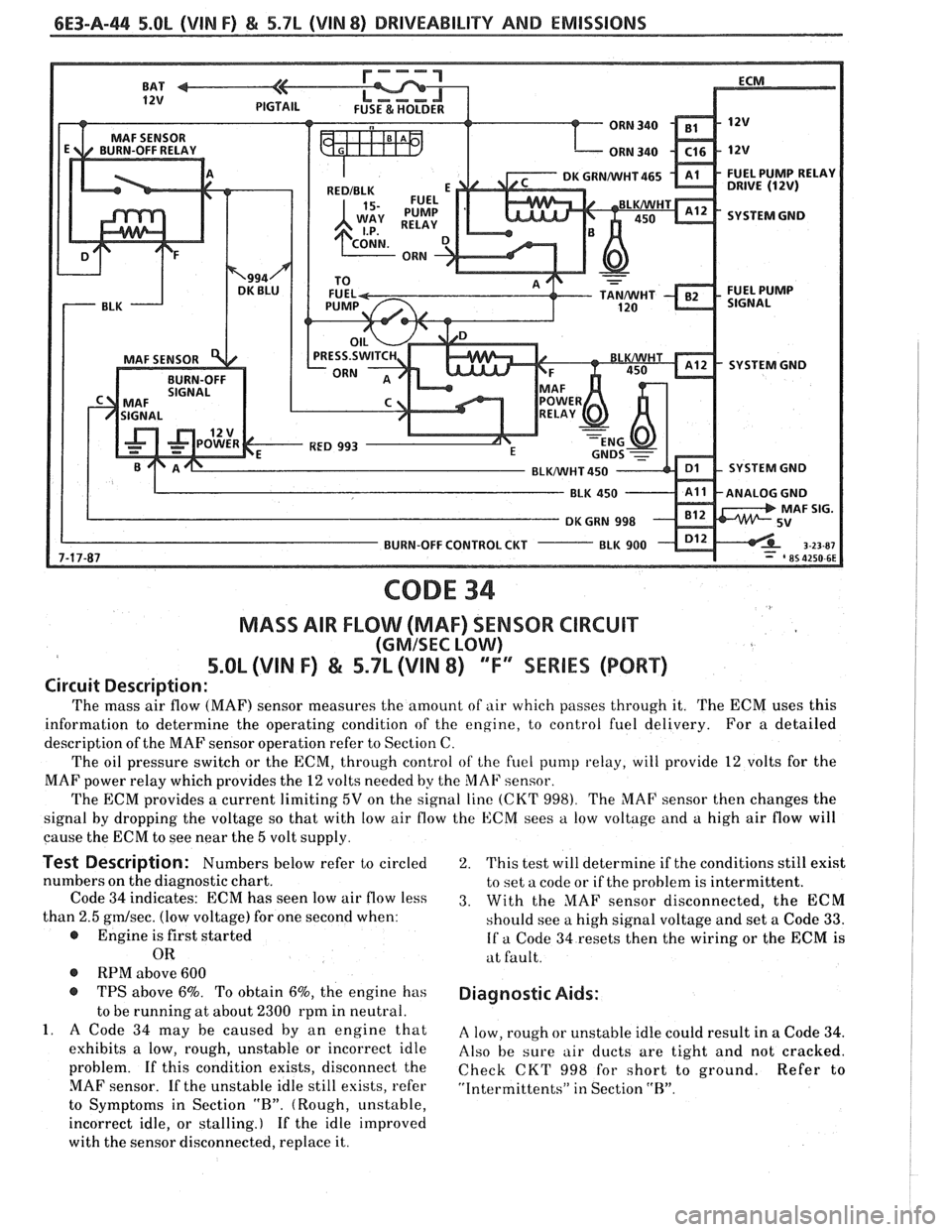
CODE 34
MASS AIR FLOW (MAF) SENSOR CIRCUIT
(GMISEC LOW)
5.OL (VIN F) & 5.7L (\/IN 8) "F"" SERIES (PORT)
Circuit Description:
The mass air flow (MAF) sensor measures the amount of air which passes through it. The ECM uses this
information to determine the operating condition of the engine, to control fuel delivery. For a detailed
description of the MAF sensor operation refer to Section C.
The oil pressure switch or the ECM, through control
of the fuel pump relay, will provide 12 volts for the
MAF power relay which provides the
12 volts needed by the MAF sensor.
The ECM provides a current limiting
5V on the signal line (CKT 998). The MAF sensor then changes the
signal by dropping the voltage so that with low air flow the ECM sees
a low voltage and a high air flow will
cause the ECM to see near the
5 volt supply.
Test Description: Numbers below refer to circled
numbers on the diagnostic chart.
Code
34 indicates: ECM has seen low air flow less
than
2.5 gmlsec. (low voltage) for one second when:
@ Engine is first started
OR
@ RPM above 600
@ TPS above 6%. To obtain 6%, the engine has
to be running at about
2300 rpm in neutral.
1. A Code 34 may be caused by an engine that
exhibits a low, rough, unstable or incorrect idle
problem. If this condition exists, disconnect the
MAF sensor. If the unstable idle still esists, refer
to Symptoms in Section
"R". (Rough, unstable,
incorrect idle, or stalling.) If the idle improved
with the sensor disconnected, replace it.
2. This test will determine if the conditions still exist
to set a code or if the problem is intermittent.
3. With the MAF sensor disconnected, the ECM
should see a high signal voltage and set a Code
33.
If a Code 34 resets then the wiring or the ECM is
at fault.
Diagnostic Aids:
A low, rough or unstable idle could result in a Code 34.
Also be sure air ducts are tight and not cracked.
Check CKT
998 for short to ground. Refer to
"Intermittents" in Section "R".
Page 849 of 1825
6E3-A-46 5.Ob (VIN F) & 5.7b (VIN 8) DRIVEABILITY AND EMISSIONS
SYSTEM GND
SYSTEM GND
SYSTEM GND
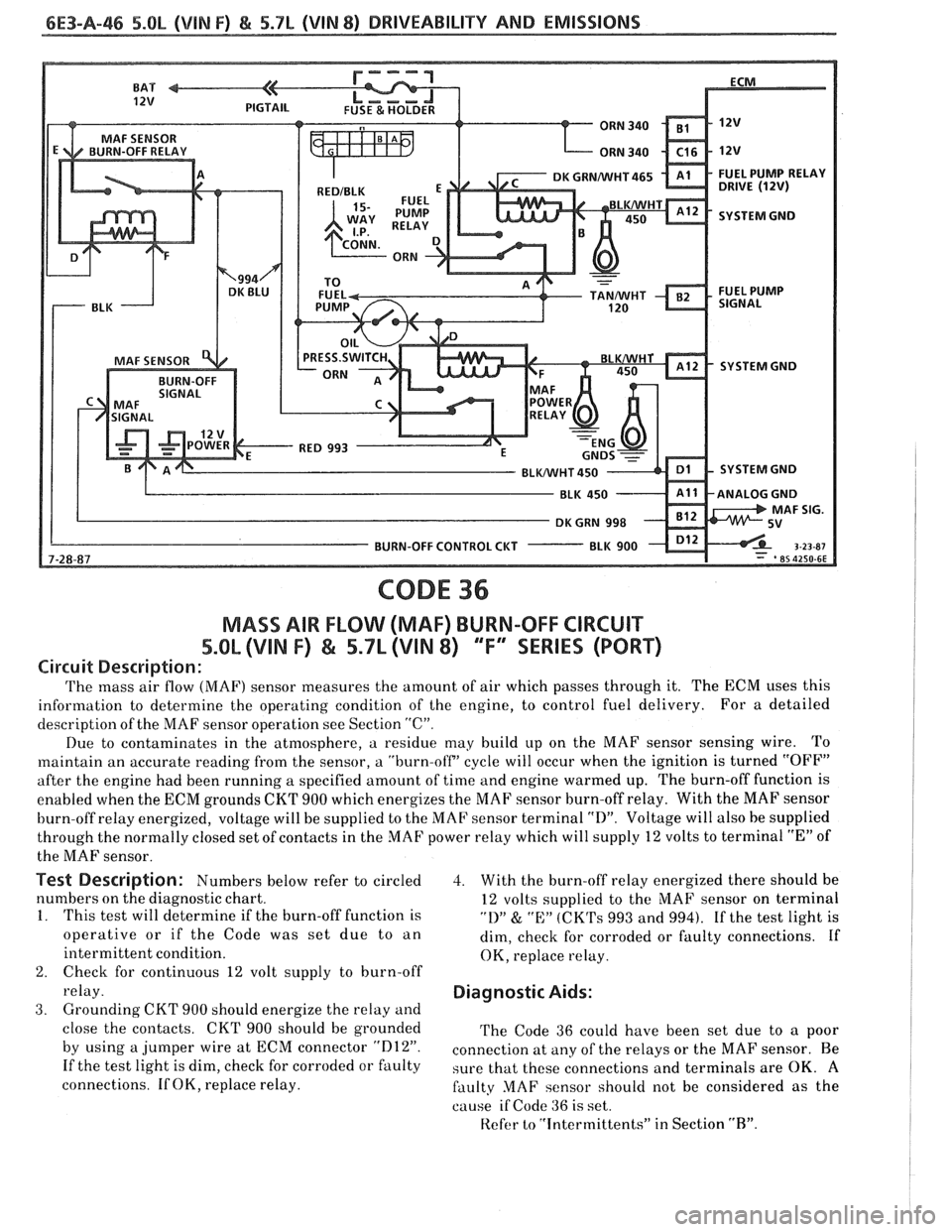
CODE 36
MASS AIR FLOW (MAF) BURN-OFF CIRCUIT
5.Qh (VlN F) & 5.7L (VIN 8) ""F9SERlES (PORT)
Circuit Description:
The mass air flow (MAF) sensor measures the amount of air which passes through it. The ECM uses this
information to determine the operating condition of the engine, to control fuel delivery. For
a detailed
description of the MAF sensor operation see Section
"C".
Due to contaminates in the atmosphere, a residue may build up on the MAF sensor sensing wire. To
maintain an accurate reading from the sensor, a "burn-off' cycle will occur when the ignition is turned "OFF"
after the engine had been running a specified amount of time and engine warmed up. The burn-off function is
enabled when the ECM grounds
CKT 900 which energizes the MAF sensor burn-off relay. With the MAF sensor
burn-off relay energized, voltage will be supplied to the MAF sensor terminal
"D". Voltage will also be supplied
through the normally closed set of contacts in the MAF power relay which will supply 12 volts to terminal
"E" of
the MAF sensor.
Test Description: Numbers below refer to circled
numbers on the diagnostic chart.
1. This test will determine if the burn-off function is
operative or if the Code was set due to an
intermittent condition.
2. Check for continuous 12 volt supply to burn-off
relay.
3. Grounding CKT 900 should energize the relay and
close the contacts. CKT 900 should be grounded
by using a jumper wire at ECM connector
"D12".
If the test light is dim, check for corroded or faulty
connections. If OK, replace relay.
3. With the burn-off relay energized there should be
12 volts supplied to the MAF sensor on terminal
"1)" & "E:" (CK'I's 993 and 994). If the test light is
dim, check for corroded or faulty connections. If
OK, replace relay.
Diagnostic Aids:
The Code 36 could have been set due to a poor
connection at
any of the relays or the MAF sensor. Be
sure that these connections and terminals are OK.
A
faulty MAF sensor should not be considered as the
cause
if Code 36 is set.
Refer
to "intermittents" in Section "R".
Page 863 of 1825
6E3-A-60 .5.0L (VIN F) & 5.7L (VIN 8) DRIVEABILITY AND EMISSIONS
340 - ORN
BULKHEAD CONN.
RELAY DRIVE
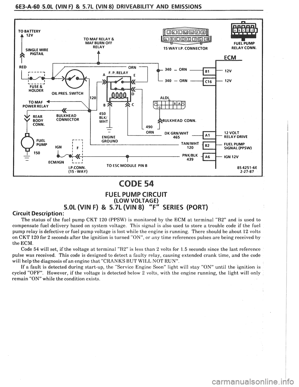
CODE 54
FUEL PUMP CIRCUIT
(LOW VOLTAGE)
5.OL (VIN F) & 5.7L (VIIN 8) "F" WRIES (PORT)
Circuit Description:
The status of the fuel pump CKT 120 (PPSW) is monitored by the ECM at terminal "H2" and is used to
compensate fuel delivery based on system voltage. This signal is also used to store a trouble code if the fuel
pump relay is defective or fuel pump voltage is lost while the engine is running. There should be about 12 volts
on CKT
120 for 2 seconds after the ignition is turned "ON", or any time references pulses are being received by
the ECM.
Code
54 will set, if the voltage at terminal "R2" is less than 2 volts for 1.5 seconds since the last reference
pulse was received. This code is designed to detect a faulty relay, causing extended crank time, and the code
will help the diagnosis of an engine that
"CRANKS BUT WILL NOT RUN".
If a fault is detected during start-up, the "Service Engine Soon" light will stay "ON" until the ignition is
cycled "OFF". However, if the voltage is detected below
2 volts, with the engine running, the light will only
remain "ON" while the condition exists.
Page 867 of 1825
6E3-B-2 5.OL (VIN F) & 5.7L (VIN 8) DRIVEABILITY AND EMISSIONS
Problem may or may not turn "ON" the "Service Engine Soon" light, or store a code.
DO NOT use the Trouble Code Charts in
An intermittent "Service Engine Soon" light
Section A for intermittent problems. The fault must
with no stored code may be caused by:
be present to locate the problem. If a fault is
@ Ignition coil shorted to ground and arcing at
intermittent, use of Trouble Code Charts
may result
spark plug wires or plugs.
in replacement of good parts.
"Service Engine Soon" light wire to
ECM
@ Most intermittent problems are caused by
shorted to ground. (CKT 419).
faulty electrical connections or wiring. Perform
Diagnostic "Test" Terminal wire to ECM,
careful check as described at start of Section
shorted to
ground.(CKT 451)
"B". Check for:
@ ECM power grounds. See ECSI wiring
@ Poor mating of the connector halves, or diagrams.
terminals not fully seated in the connector
@ Loss of trouble code memory. To check,
body (backed out). disconnect TPS and idle engine until "Service
@ Improperly formed or damaged terminals.
Engine Soon" light comes on. Code 22 should be
All connector terminals in problem circuit
stored, and kept in memory when ignition is
should be carefully reformed or replaced to turned "OFF". If not, the ECM is faulty.
insure proper contact tension.
@ Check for an electrical system interference
@ Poor terminal to wire connection. This caused by a defective relay, ECM driven
requires removing the terminal from the
solenoid, or switch. They can cause a sharp
connector body to check. See "Introduction"
electrical surge. Normally, the problem will
to Section
"6E". occur when the faulty component is operated.
@ If a visual check does not find the cause of the @ Check for improper installation of electrical
problem, the car can be driven with a voltmeter
options, such as lights,
%way radios, etc.
connected to
a suspected circuit. A "Scan" tool
EST wires should be kept away from spark plug
can also be used for monitoring input signals to wires, distributor wires, distributor housing,
the ECM to help detect intermittent conditions. coil, and generator. Wire from
ECM to
An abnormal voltage, or "Scan" reading, when distributor
(CKT 453) should be a good
the problem occurs, indicates the problem
may connection.
be in that circuit. If the wiring and connectors
@ Check for open diode across AIC compressor
check OK and a Trouble Code was stored for a
clutch, and for other open diodes (see wiring
circuit having a sensor, except for Codes
43, 44, diagrams).
and 45, substitute a known good sensor and
recheck.
HARD START
Definition: Engine cranks OK, but does not start for a long
time. Does eventually run, or may start but immediately dies.
Perform careful check as described at start of
Section
"B".
@ Make sure driver is using correct starting
procedure.
@ CHECK:
- TPS for sticking or binding or a high TPS
voltage with the throttle closed (should read
less than
.700 volts).
- High resistance in coolant sensor circuit or
sensor itself. See Code 15 chart or with
a
"Scan" tool compare coolant temperature with
ambient temperature on a cold engine.
- Fuel pressure CHART A-7.
- Water contaminated fuel.
- EGR operation. Be sure valve seats properly and
is not staying open. See CHART C-7.
- Both injector fuses (visually inspect).
- Ignition system - Check distributor for:
Proper Output with ST-125.
Worn shaft.
Bare and shorted wires.
Pickup coil resistance and connections.
Loose ignition coil ground.
Moisture in distributor cap.
@ If problem exists in cold weather, check cold start
valve. See CHART A-9.
Page 876 of 1825
DRIVEABILITY AND EMISSIONS 5.0L (VIN F) & 5.7L (VIN 8) 6E3-C1-1
SECTION C1
ELECTRONlC CONTROL MODULE (ECM) AND SENSORS
CONTENTS
GENERAL DESCRIPTION ................ C1-I
ELECTRONIC CONTROL MODULE ....... C1-I
PJIEM-CAL......................... C1-I
ECM Function.. .................. C1-I
INFORMATION SENSORS ............. Cl-2
Engine Coolant Temperature Sensor . . C1-2
MAF Sensor ..................... C1-2
MAT Sensor .................... C1-2
Oxygen (02) Sensor. ............... C1-3
Throttle Position Sensor ............ C1-3
Knocksensor .................... C1-3
Vehicle Speed Sensor .............. C1-3
...... ParkINeutral Switch (Auto Only) C1-3
NC "ON" Signal .................. C1-4
Distributor Reference Signal ......... C1-4
DIAGNOSIS
......................... C1-4
ECM............................. C1-4
MEM-CAL......................... C1-4
ECMINPUTS....................... C1-4
........ Coolant Temperature Sensor C1-5
GENERAL DESCRIPTION
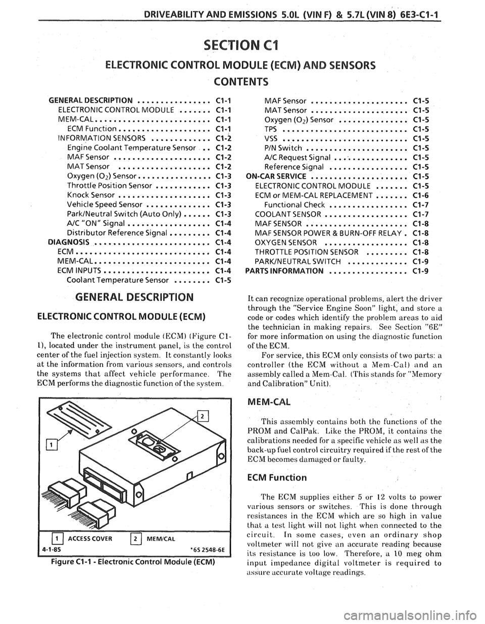
ELECTRONIC CONTROL MODULE (ECM)
The electronic control [nodule (ECM) (Figure C1-
11, located under the instrument panel, is the control
center of the fuel injection system. It constantly looks
at the information from various sensors,
and controls
the systems that affect vehicle performance. The
ECM performs the diagnostic function of the system.
-- Figure C1-1 - Electronic Control Module (ECM)
MAF Sensor ..................... C1-5
MAT Sensor ..................... C1-5
Oxygen (02) Sensor ............... C1-5
TPS ........................... C1-5
VSS ........................... C1-5
PIN Switch ...................... C1-5
NC Request Signal ................ C1-5
Reference Signal ................. C1-5
ON-CAR SERVICE
..................... C1-5
ELECTRONIC CONTROL MODULE ....... C1-5
ECM or MEM-CAL REPLACEMENT ....... C1-6
Funct~onal Check ................. C1-7
COOLANT SENSOR .................. C1-7
MAFSENSOR ...................... C1-8
MAF SENSOR POWER & BURN-OFF RELAY . C1-8
OXYGEN SENSOR .................. C1-8
THROTTLE POSITION SENSOR ......... C1-8
PARKINEUTRAL SWITCH ............. C1-9
PARTS INFORMATION
................. C1-9
It can recognize operational problems, alert the driver
through the "Service Engine Soon" light, and store a
code or codes which identify the problem areas to aid
the technician in making repairs. See Section
"6E"
for more information on using the diagnostic function
of the
ECM.
For service, this ECM only consists of two parts: a
controller (the ECM without a
Mem-Cal) and an
assembly called a Mem-Cal. (This stands for "Memory
and Calibration" Unit).
M EM-CAL
This assembly contains both thc functions of thc
PROM and CalPak. Like the PROM, it contains the
calibrations needed for a specific vehicle as well as the
back-up fuel control circuitry required if the rest of the
ECM becomes damaged or faulty.
ECM Function
The ECM supplies either 5 or 12 volts to power
various sensors or switches.
This is done through
resistances in the ECM which are so high in value
that a test light will not light when connected to the
circuit.
In some cases, even an ordinary shop
voltmeter will not give an accurate reading because
its resistance is too low. Therefore, a
10 nleg ohm
input impedance digital voltmeter is
requircd to
assure accurate voltage readings.