1988 OPEL CALIBRA check oil
[x] Cancel search: check oilPage 215 of 525
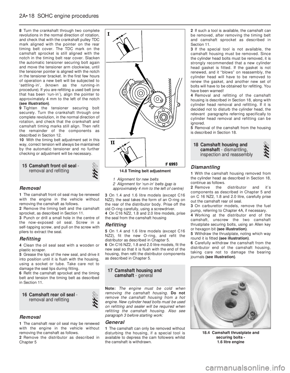
8Turn the crankshaft through two complete
revolutions in the normal direction of rotation,
and check that with the crankshaft pulley TDC
mark aligned with the pointer on the rear
timing belt cover. The TDC mark on the
camshaft sprocket is still aligned with the
notch in the timing belt rear cover. Slacken
the automatic tensioner securing bolt again
and move the tensioner arm clockwise, until
the tensioner pointer is aligned with the notch
in the tensioner bracket. In the first few hours
of operation a new belt will be subjected to
‘settling-in’, (known as the running-in
procedure). If you are refitting a used belt (one
that has been ‘run-in’), align the pointer to
approximately 4 mm to the left of the notch
(see illustration).
9Tighten the tensioner securing bolt
securely. Turn the crankshaft through one
complete revolution, in the normal direction of
rotation, and check that the crankshaft and
camshaft timing marks still align. Then refit
the remainder of the components as
described in Section 12.
10With the timing belt adjustment set in this
way, correct tension will always be maintained
by the automatic tensioner and no further
checking or adjustment will be necessary.
15Camshaft front oil seal -
removal and refitting
3
Removal
1The camshaft front oil seal may be renewed
with the engine in the vehicle without
removing the camshaft as follows.
2Remove the timing belt and the camshaft
sprocket, as described in Section 11.
3Punch or drill a small hole in the centre of
the now-exposed oil seal. Screw in a
self-tapping screw, and pull on the screw with
pliers to extract the seal.
Refitting
4Clean the oil seal seat with a wooden or
plastic scraper.
5Grease the lips of the new seal, and drive it
into position until it is flush with the housing,
using a socket or tube. Take care not to
damage the seal lips during fitting.
6Refit the camshaft sprocket and the timing
belt and tension the timing belt as described
in Section 11.
16Camshaft rear oil seal -
removal and refitting
3
Removal
1The camshaft rear oil seal may be renewed
with the engine in the vehicle without
removing the camshaft as follows.
2Remove the distributor as described in
Chapter 53On 1.4 and 1.6 litre models (except C16
NZ2), the seal takes the form of an O-ring on
the rear of the distributor body. Prise off the
old O-ring carefully, using a screwdriver.
4On C16 NZ2, 1.8 and 2.0 litre models, prise
the seal from the camshaft housing
Refitting
5 On 1.4 and 1.6 litre models (except C16
NZ2), fit the new O-ring, and refit the
distributor as described in Chapter 5.
6On C16 NZ2, 1.8 and 2.0 litre models, fit the
new seal so that it is flush with the end of the
housing, then refit the distributor components
as described in Chapter 5.
17Camshaft housing and
camshaft -general
Note: The engine must be cold when
removing the camshaft housing. Do not
remove the camshaft housing from a hot
engine. New cylinder head bolts must be used
on refitting and sealer will be required when
refitting the camshaft housing. Also see
paragraph 3 before starting work:
General
1The camshaft can only be removed without
disturbing the housing, if a special tool is
available to depress the cam followers whilst
the camshaft is withdrawn.2If such a tool is available, the camshaft can
be removed, after removing the timing belt
and camshaft sprocket as described in
Section 11.
3If the special tool is not available, the
camshaft housing must be removed. Since
the cylinder head bolts must be removed, it is
strongly recommended that a new cylinder
head gasket is fitted. If the gasket is not
renewed, and it “blows” on reassembly, the
cylinder head will have to be removed to
renew the gasket, and another new set of
bolts will have to be obtained for refitting. You
have been warned!
4Removal and refitting of the camshaft
housing is described in Section 18, along with
cylinder head removal and refitting. If it is
decided not to disturb the cylinder head, the
relevant paragraphs referring specifically to
cylinder head removal and refitting can be
ignored.
5Removal of the camshaft from the housing
is described in Section 18.
18Camshaft housing and
camshaft - dismantling,
inspection and reassembly
4
Dismantling
1With the camshaft housing removed from
the cylinder head as described in Section 18,
continue as follows.
2Remove the distributor and it’s
components as described in Chapter 5 and
on C 16 NZ2, 1.8 and 2.0 litre, carefully prise
out the camshaft rear oil seal.
3On carburettor models, remove the fuel
pump, referring to Chapter 4A, if necessary.
4Working at the distributor end of the
camshaft, unscrew the two camshaft
thrustplate securing bolts, using an Allen key
or hexagon bit (see illustration).
5Withdraw the thrustplate, noting which way
round it is fitted (see illustration).
6Carefully withdraw the camshaft from the
distributor end of the camshaft housing,
taking care not to damage the bearing
journals (see illustration).
2A•18SOHC engine procedures
14.8 Timing belt adjustment
1 Alignment for new belts
2 Alignment for ‘run-in’ belts (gap is
approximately 4 mm to the left of centre)
18.4 Camshaft thrustplate and
securing bolts -
1.6 litre engine
Page 216 of 525
Inspection
7With the camshaft removed, examine the
bearings in the camshaft housing for signs of
obvious wear or pitting. If evident, a new
camshaft housing will probably be required.
8The camshaft itself should show no marks
or scoring on the journal or cam lobe
surfaces. If evident, renew the camshaft. Note
that if the camshaft is renewed, all the rocker
arms should also be renewed.
9Check the camshaft thrustplate for signs of
wear or grooves, and renew if evident.
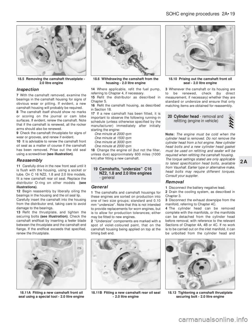
10It is advisable to renew the camshaft front
oil seal as a matter of course if the camshaft
has been removed. Prise out the old seal
using a screwdriver (see illustration).
Reassembly
11Carefully drive in the new front seal until it
is flush with the housing, using a socket or
tube. On C 16 NZ2, 1.8 and 2.0 litre models,
fit a new camshaft rear oil seal. Replace the
distributor O-ring on other models (see
illustrations).
12Begin reassembly by liberally oiling the
bearings in the housing and the oil seal lip.
Carefully insert the camshaft into the housing
from the distributor end, taking care to avoid
damage to the bearings.
13Refit the thrustplate, and tighten the
securing bolts (see illustration). Check the
camshaft endfloat by inserting a feeler blade
between the thrustplate and the camshaft end
flange. If the endfloat exceeds that specified,
renew the thrustplate.14Where applicable, refit the fuel pump,
referring to Chapter 4, if necessary.
15Refit the distributor as described in
Chapter 5.
16Refit the camshaft housing, as described
in Section 18.
17If a new camshaft has been fitted, it is
important to observe the following running-in
schedule (unless otherwise specified by the
manufacturer) immediately after initially
starting the engine:
One minute at 2000 rpm
One minute at 1500 rpm
One minute at 3000 rpm
One minute at 2000 rpm
18Change the engine oil (but not the filter,
unless due) approximately 600 miles (1000
km) after fitting a new camshaft.19Camshafts, “undersize” C16
NZ2, 1.8 and 2.0 litre engines
- general
General
1The camshafts and camshaft housings for
these engines are sorted on production into
one of two size groups; standard and 0.10
mm “undersize”. Note that this is not intended
to provide replacements for worn engines, but
is to allow for production tolerances; either
may be fitted to new engines.
2“Undersize” components are marked with a
spot of violet-coloured paint, that on the
camshaft housing being applied on top at the
timing belt end.3Whenever the camshaft or its housing are
to be renewed, check (by direct
measurement, if necessary) whether they are
standard or undersize and ensure that only
matching items are obtained for reassembly.
20Cylinder head - removal and
refitting (engine in vehicle)
4
Note: The engine must be cold when the
cylinder head is removed. Do not remove the
cylinder head from a hot engine. New cylinder
head bolts and a new cylinder head gasket
must be used on refitting and sealer will be
required when refitting the camshaft housing.
The torque settings stated are only applicable
to latest specification head bolts, available
from Vauxhall. Earlier type or alternative make,
head bolts may require different torques.
Consult your supplier.
Removal
1Disconnect the battery negative lead.
2Drain the cooling system, as described in
Chapter 3.
3Disconnect the exhaust downpipe from the
manifold, referring to Chapter 4C.
4The cylinder head can be removed
complete with the manifolds, or the manifolds
can be detached from the cylinder head
before removal, with reference to the relevant
Sections of Chapter 4A, 4B or 4C. If no work
is to be carried out on the inlet manifold, it can
be unbolted from the cylinder head and
SOHC engine procedures 2A•19
18.10 Prising out the camshaft front oil
seal - 2.0 litre engine
18.13 Tightening a camshaft thrustplate
securing bolt - 2.0 litre engine18.11B Fitting a new camshaft rear oil seal
- 2.0 litre engine18.11A Fitting a new camshaft front oil
seal using a special tool - 2.0 litre engine
18.6 Withdrawing the camshaft from the
housing - 2.0 litre engine18.5 Removing the camshaft thrustplate -
2.0 litre engine
2A
Page 217 of 525
supported to one side out of the way, thus
avoiding the need to disconnect the relevant
hoses, pipes and wiring.
5If the cylinder head is to be removed
complete with the manifolds, disconnect all
relevant hoses, pipes and wiring from the inlet
manifold and associated components,
referring to Chapter 4A or 4B. On carburettor
models, disconnect the hot air hose from the
shroud on the exhaust manifold. Loosen the
alternator mountings, with reference to
Chapter 5, then unbolt the upper alternator
mounting from the inlet manifold.
6If the inlet manifold is to be left in the engine
compartment, continue as follows, otherwise
go on to paragraph 15.
7Disconnect the air cleaner trunking from the
air box on the carburettor or throttle body, or
directly from the throttle body (as applicable),
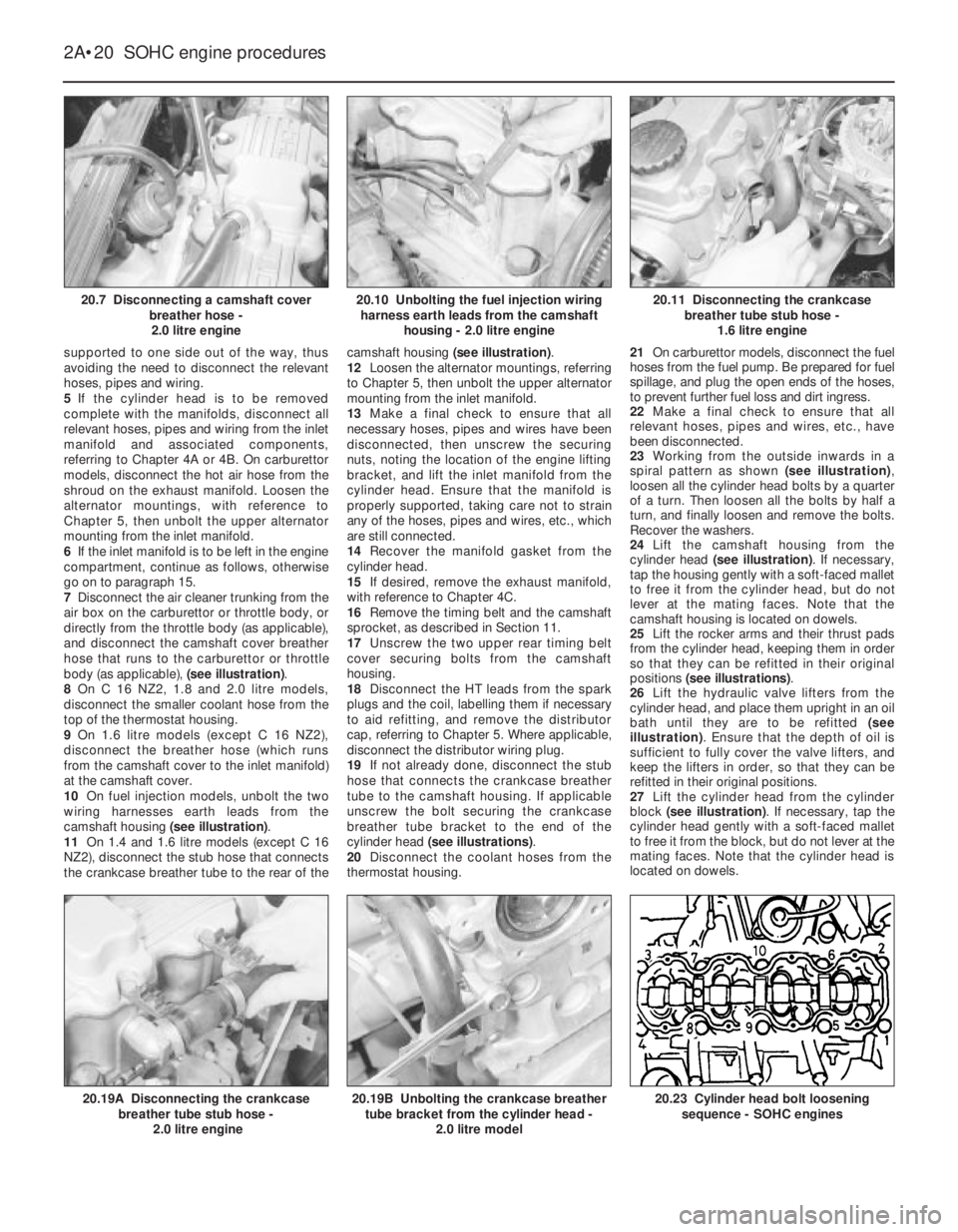
and disconnect the camshaft cover breather
hose that runs to the carburettor or throttle
body (as applicable), (see illustration).
8On C 16 NZ2, 1.8 and 2.0 litre models,
disconnect the smaller coolant hose from the
top of the thermostat housing.
9On 1.6 litre models (except C 16 NZ2),
disconnect the breather hose (which runs
from the camshaft cover to the inlet manifold)
at the camshaft cover.
10On fuel injection models, unbolt the two
wiring harnesses earth leads from the
camshaft housing (see illustration).
11On 1.4 and 1.6 litre models (except C 16
NZ2), disconnect the stub hose that connects
the crankcase breather tube to the rear of thecamshaft housing (see illustration).
12Loosen the alternator mountings, referring
to Chapter 5, then unbolt the upper alternator
mounting from the inlet manifold.
13Make a final check to ensure that all
necessary hoses, pipes and wires have been
disconnected, then unscrew the securing
nuts, noting the location of the engine lifting
bracket, and lift the inlet manifold from the
cylinder head. Ensure that the manifold is
properly supported, taking care not to strain
any of the hoses, pipes and wires, etc., which
are still connected.
14Recover the manifold gasket from the
cylinder head.
15If desired, remove the exhaust manifold,
with reference to Chapter 4C.
16Remove the timing belt and the camshaft
sprocket, as described in Section 11.
17Unscrew the two upper rear timing belt
cover securing bolts from the camshaft
housing.
18Disconnect the HT leads from the spark
plugs and the coil, labelling them if necessary
to aid refitting, and remove the distributor
cap, referring to Chapter 5. Where applicable,
disconnect the distributor wiring plug.
19If not already done, disconnect the stub
hose that connects the crankcase breather
tube to the camshaft housing. If applicable
unscrew the bolt securing the crankcase
breather tube bracket to the end of the
cylinder head (see illustrations).
20Disconnect the coolant hoses from the
thermostat housing.21On carburettor models, disconnect the fuel
hoses from the fuel pump. Be prepared for fuel
spillage, and plug the open ends of the hoses,
to prevent further fuel loss and dirt ingress.
22Make a final check to ensure that all
relevant hoses, pipes and wires, etc., have
been disconnected.
23Working from the outside inwards in a
spiral pattern as shown (see illustration),
loosen all the cylinder head bolts by a quarter
of a turn. Then loosen all the bolts by half a
turn, and finally loosen and remove the bolts.
Recover the washers.
24Lift the camshaft housing from the
cylinder head (see illustration). If necessary,
tap the housing gently with a soft-faced mallet
to free it from the cylinder head, but do not
lever at the mating faces. Note that the
camshaft housing is located on dowels.
25Lift the rocker arms and their thrust pads
from the cylinder head, keeping them in order
so that they can be refitted in their original
positions (see illustrations).
26Lift the hydraulic valve lifters from the
cylinder head, and place them upright in an oil
bath until they are to be refitted (see
illustration). Ensure that the depth of oil is
sufficient to fully cover the valve lifters, and
keep the lifters in order, so that they can be
refitted in their original positions.
27Lift the cylinder head from the cylinder
block (see illustration). If necessary, tap the
cylinder head gently with a soft-faced mallet
to free it from the block, but do not lever at the
mating faces. Note that the cylinder head is
located on dowels.
2A•20SOHC engine procedures
20.7 Disconnecting a camshaft cover
breather hose -
2.0 litre engine20.11 Disconnecting the crankcase
breather tube stub hose -
1.6 litre engine
20.23 Cylinder head bolt loosening
sequence - SOHC engines20.19B Unbolting the crankcase breather
tube bracket from the cylinder head -
2.0 litre model20.19A Disconnecting the crankcase
breather tube stub hose -
2.0 litre engine
20.10 Unbolting the fuel injection wiring
harness earth leads from the camshaft
housing - 2.0 litre engine
Page 219 of 525
40Refit the camshaft sprocket and the
timing belt and tension the timing belt as
described in Section 11.
41Where applicable, refit the manifolds to
the cylinder head, with reference to Chapter
4A, 4B or 4C, using new gaskets.
42Reconnect the exhaust downpipe to the
manifold, using a new gasket, referring to
Chapter 4C, if necessary.
43Refit the upper alternator mounting to the
inlet manifold, then adjust the alternator
drivebelt tension, as described in Chapter 5.
44Refill the cooling system, as described in
Chapter 3.
45On completion, check that all relevant
hoses, pipes and wires, etc., have been
reconnected.
46When the engine is started, check for
signs of leaks.
47Once the engine has reached normal
operating temperature, check and if
necessary adjust the idle speed (where
applicable) and the mixture (where
applicable), with reference to Chapter 4A or
4B.
21Cylinder head - removal and
refitting (engine removed)
4
Note: New cylinder head bolts and a new
cylinder head gasket must be used on
refitting, and sealer will be required when
refitting the camshaft housing.
The torque settings stated are only applicable
to latest specification head bolts, available
from Vauxhall. Earlier type or alternative make,
head bolts may require different torques.
Consult your supplier.
Removal
1The cylinder head can be removed
complete with the manifolds, or the manifolds
can be detached from the cylinder head
before removal, with reference Chapter 4A,
4B or 4C.
2Remove the timing belt and the camshaft
sprocket, as described in Section 11.
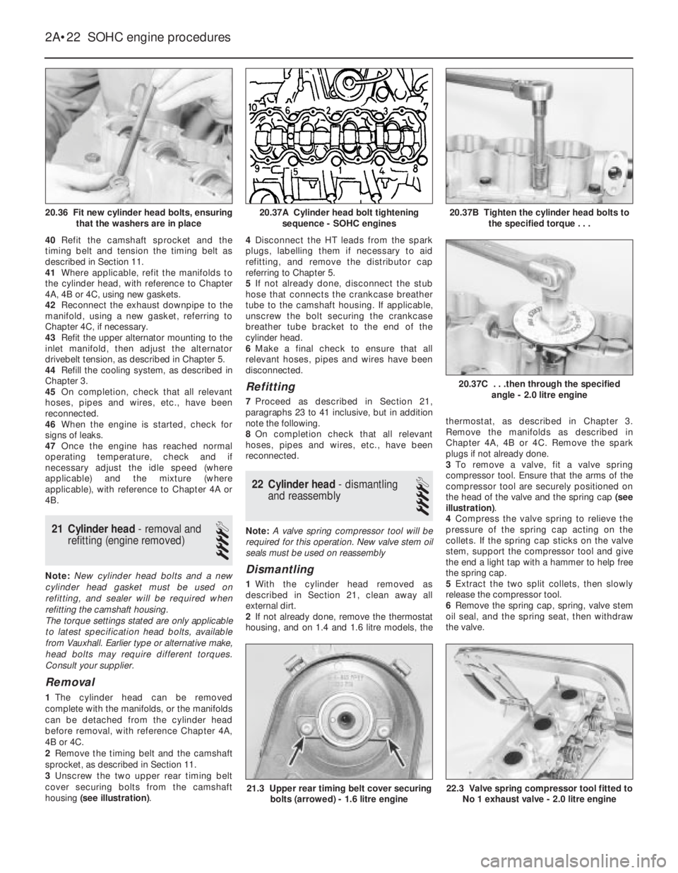
3Unscrew the two upper rear timing belt
cover securing bolts from the camshaft
housing (see illustration).4Disconnect the HT leads from the spark
plugs, labelling them if necessary to aid
refitting, and remove the distributor cap
referring to Chapter 5.
5If not already done, disconnect the stub
hose that connects the crankcase breather
tube to the camshaft housing. If applicable,
unscrew the bolt securing the crankcase
breather tube bracket to the end of the
cylinder head.
6Make a final check to ensure that all
relevant hoses, pipes and wires have been
disconnected.
Refitting
7Proceed as described in Section 21,
paragraphs 23 to 41 inclusive, but in addition
note the following.
8On completion check that all relevant
hoses, pipes and wires, etc., have been
reconnected.
22Cylinder head -dismantling
and reassembly
4
Note: A valve spring compressor tool will be
required for this operation. New valve stem oil
seals must be used on reassembly
Dismantling
1With the cylinder head removed as
described in Section 21, clean away all
external dirt.
2If not already done, remove the thermostat
housing, and on 1.4 and 1.6 litre models, thethermostat, as described in Chapter 3.
Remove the manifolds as described in
Chapter 4A, 4B or 4C. Remove the spark
plugs if not already done.
3To remove a valve, fit a valve spring
compressor tool. Ensure that the arms of the
compressor tool are securely positioned on
the head of the valve and the spring cap (see
illustration).
4Compress the valve spring to relieve the
pressure of the spring cap acting on the
collets. If the spring cap sticks on the valve
stem, support the compressor tool and give
the end a light tap with a hammer to help free
the spring cap.
5Extract the two split collets, then slowly
release the compressor tool.
6Remove the spring cap, spring, valve stem
oil seal, and the spring seat, then withdraw
the valve.
2A•22SOHC engine procedures
20.36 Fit new cylinder head bolts, ensuring
that the washers are in place20.37B Tighten the cylinder head bolts to
the specified torque . . .
22.3 Valve spring compressor tool fitted to
No 1 exhaust valve - 2.0 litre engine21.3 Upper rear timing belt cover securing
bolts (arrowed) - 1.6 litre engine
20.37C . . .then through the specified
angle - 2.0 litre engine
20.37A Cylinder head bolt tightening
sequence - SOHC engines
Page 221 of 525
23Cylinder head - inspection
and renovation
4
Note: Refer to a dealer for advice before
attempting to carry out valve grinding or valve
seat reciting operations, as these operations
may not be possible for the DIY mechanic.
This is due to the fitment of hardened valve
seats for use with unleaded petrol
Inspection
1Remember that the cylinder head is of light
alloy construction and is easily damaged, use
a blunt scraper or rotary wire brush to clean all
traces of carbon deposits from the
combustion spaces and the ports. The valve
stems and valve guides should also be freed
from any carbon deposits. Wash the
combustion spaces and ports down with
paraffin and scrape the cylinder head surface
free of any foreign matter with the side of a
steel rule, or a similar article.
2If the engine is installed in the car, clean the
pistons and the top of the cylinder bores. If
the pistons are still in the block, it is essential
that great care is taken to ensure that no
carbon gets into the cylinder bores. This could
scratch the cylinder walls or cause damage to
the pistons and rings. To ensure this does not
happen, first turn the crankshaft so that two of
the pistons are at the top of their bores. Insert
rag into the other two bores or seal them off
with paper and masking tape. The waterways
should also be covered with small pieces of
masking tape, to prevent particles of carbon
entering the cooling system and damaging the
coolant pump.
3Press a little grease into the gap between
the cylinder walls and the two pistons that are
to be worked on. With a blunt scraper,
carefully scrape away the carbon from the
piston crown, taking great care not to scratch
the aluminium. Also scrape away the carbon
from the surrounding lip of the cylinder wall.
When all carbon has been removed, scrape
away the grease that will now be
contaminated with carbon particles, taking
care not to press any into the bores. To assist
prevention of carbon build-up, the piston
crown can be polished with a metal polish.
Remove the rags or masking tape from the
other two cylinders, and turn the crankshaft
so that the two pistons that were at thebottom are now at the top. Place rag or
masking tape in the cylinders that have been
decarbonised, and continue as just described.
4Examine the heads of the valves for pitting
and burning, especially the heads of the
exhaust valves. The valve seatings should be
examined at the same time. If the pitting on
the valve and seat is very slight, the marks
can be removed by grinding the seats and
valves together with coarse, and then fine,
valve grinding paste.
5Where bad pitting has occurred to the valve
seats, it will be necessary to recut them and fit
new valves. This latter job should be entrusted
to the local dealer or engineering works. In
practice it is very seldom that the seats are so
badly worn. Normally it is the valve that is too
badly worn for refitting, and the owner can
easily buy a new set of valves and match
them to the seats by valve grinding.
Renovation
6Valve grinding is carried out as follows.
Smear a trace of coarse carborundum paste
on the seat face and apply a suction grinder
tool to the valve head. With a semi-rotary
motion, grind the valve head to its seat, lifting
the valve occasionally to redistribute the
grinding paste. When a dull matt even surface
is produced on both the valve seat and the
valve, wipe off the paste and repeat the
process with fine carborundum paste, lifting
and turning the valve to redistribute the paste
as before. A light spring placed under the
valve head will greatly ease this operation.
When a smooth unbroken ring of light grey
matt finish is produced, on both valve and
valve seat faces, the grinding operation is
complete. Carefully clean away every trace of
grinding compound, taking great care to leave
none in the ports or in the valve guides. Clean
the valves and valve seats with a
paraffin-soaked rag, then with a clean rag,
and finally, if an air line is available, blow the
valves, valve guides and valve ports clean.
7Check that all valve springs are intact. If any
one is broken, all should be renewed. Check
the free height of the springs against new
ones. If some springs are not long enough,
replace them all. Springs suffer from fatigue
and it is a good idea to renew them even if
they look serviceable. 8The cylinder head can be checked for
warping either by placing it on a piece of plate
glass or using a straight-edge and feeler
blades. If there is any doubt or if its block face
is corroded, have it re-faced by your dealer or
motor engineering works.
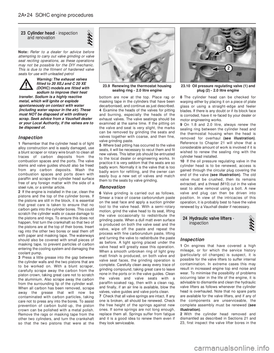
9On 1.8 and 2.0 litre, always renew the
sealing ring between the cylinder head and
the thermostat housing when the head is
removed for overhaul (see illustration).
Reference to Chapter 21 will show that a
considerable amount of work is involved if it is
wished to renew the sealing ring with the
cylinder head installed.
10If the oil pressure regulating valve in the
cylinder head is to be renewed, access is
gained through the circular plug covering the
end of the valve (see illustration). The old
valve must be crushed, then its remains
extracted, and a thread (M10) cut in the valve
seat to allow removal using a bolt. A new
valve and plug can then be driven into
position. In view of the intricacies of this
operation, it is probably best to have the valve
renewed by a Vauxhall dealer if necessary.
24Hydraulic valve lifters -
inspection
4
Inspection
1On engines that have covered a high
mileage, or for which the service history
(particularly oil changes) is suspect, it is
possible for the valve lifters to suffer internal
contamination. In extreme cases this may
result in increased engine top end noise and
wear. To minimise the possibility of problems
occurring later in the life of the engine, it is
advisable to dismantle and clean the hydraulic
valve lifters as follows whenever the cylinder
head is overhauled. Note that no spare parts
are available for the valve lifters, and if any of
the components are unserviceable, the
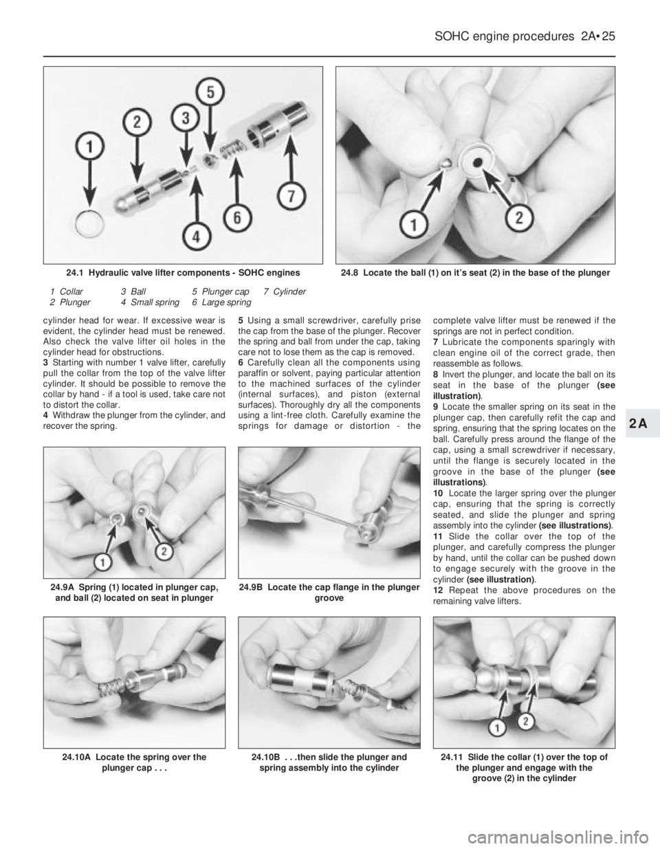
complete assembly must be renewed (see
illustration).
2With the cylinder head removed and
dismantled as described in Sections 21 and
23, first inspect the valve lifter bores in the
2A•24SOHC engine procedures
23.10 Oil pressure regulating valve (1) and
plug (2) - 2.0 litre engine23.9 Renewing the thermostat housing
sealing ring - 2.0 litre engine
Warning: The exhaust valves
fitted to 20 XEJ and C 20 XE
(DOHC) models are fitted with
sodium to improve their heat
transfer. Sodium is a highly reactive
metal, which will ignite or explode
spontaneously on contact with water
(including water vapour in the air). These
must NOT be disposed of with ordinary
scrap. Seek advice from a Vauxhall dealer
or your Local Authority, if the valves are to
be disposed of.
Page 222 of 525
cylinder head for wear. If excessive wear is
evident, the cylinder head must be renewed.
Also check the valve lifter oil holes in the
cylinder head for obstructions.
3Starting with number 1 valve lifter, carefully
pull the collar from the top of the valve lifter
cylinder. It should be possible to remove the
collar by hand -if a tool is used, take care not
to distort the collar.
4Withdraw the plunger from the cylinder, and
recover the spring.5Using a small screwdriver, carefully prise
the cap from the base of the plunger. Recover
the spring and ball from under the cap, taking
care not to lose them as the cap is removed.
6Carefully clean all the components using
paraffin or solvent, paying particular attention
to the machined surfaces of the cylinder
(internal surfaces), and piston (external
surfaces). Thoroughly dry all the components
using a lint-free cloth. Carefully examine the
springs for damage or distortion -thecomplete valve lifter must be renewed if the
springs are not in perfect condition.
7Lubricate the components sparingly with
clean engine oil of the correct grade, then
reassemble as follows.
8Invert the plunger, and locate the ball on its
seat in the base of the plunger (see
illustration).
9Locate the smaller spring on its seat in the
plunger cap, then carefully refit the cap and
spring, ensuring that the spring locates on the
ball. Carefully press around the flange of the
cap, using a small screwdriver if necessary,
until the flange is securely located in the
groove in the base of the plunger (see
illustrations).
10Locate the larger spring over the plunger
cap, ensuring that the spring is correctly
seated, and slide the plunger and spring
assembly into the cylinder (see illustrations).
11Slide the collar over the top of the
plunger, and carefully compress the plunger
by hand, until the collar can be pushed down
to engage securely with the groove in the
cylinder (see illustration).
12Repeat the above procedures on the
remaining valve lifters.
SOHC engine procedures 2A•25
24.11 Slide the collar (1) over the top of
the plunger and engage with the
groove (2) in the cylinder24.10B . . .then slide the plunger and
spring assembly into the cylinder
24.9B Locate the cap flange in the plunger
groove24.9A Spring (1) located in plunger cap,
and ball (2) located on seat in plunger
24.10A Locate the spring over the
plunger cap . . .
24.8 Locate the ball (1) on it’s seat (2) in the base of the plunger24.1 Hydraulic valve lifter components - SOHC engines
1 Collar
2 Plunger3 Ball
4 Small spring5 Plunger cap
6 Large spring7 Cylinder
2A
Page 223 of 525
25Flywheel -removal, inspection
and refitting
4
Note: New flywheel securing bolts must he
used on refitting. Certain models are fitted
with a ‘Pot type’ flywheel. Although, it has a
deeply recessed surface for the clutch disc,
the operations below are the same.
Removal
1If not already done, remove the clutch,
(Chapter 6), and the starter motor, (Chapter 5).
2If the engine is in the vehicle, remove the
clutch release bearing and its guide sleeve, as
described in Chapter 6.
3Although the flywheel bolt holes are offset
so that the flywheel can only be fitted in one
position, it will make refitting easier if
alignment marks are made between the
flywheel and the end of the crankshaft.
4Prevent the flywheel from turning by
jamming the ring gear teeth using a large
screwdriver or similar tool. Access is most
easily obtained through the starter motor
aperture if the engine is in the vehicle.
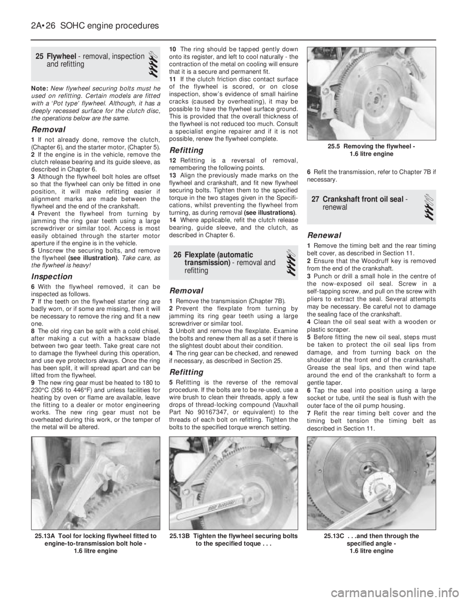
5Unscrew the securing bolts, and remove
the flywheel (see illustration). Take care, as
the flywheel is heavy!
Inspection
6With the flywheel removed, it can be
inspected as follows.
7If the teeth on the flywheel starter ring are
badly worn, or if some are missing, then it will
be necessary to remove the ring and fit a new
one.
8The old ring can be split with a cold chisel,
after making a cut with a hacksaw blade
between two gear teeth. Take great care not
to damage the flywheel during this operation,
and use eye protectors always. Once the ring
has been split, it will spread apart and can be
lifted from the flywheel.
9The new ring gear must be heated to 180 to
230°C (356 to 446°F) and unless facilities for
heating by oven or flame are available, leave
the fitting to a dealer or motor engineering
works. The new ring gear must not be
overheated during this work, or the temper of
the metal will be altered.10The ring should be tapped gently down
onto its register, and left to cool naturally -the
contraction of the metal on cooling will ensure
that it is a secure and permanent fit.
11If the clutch friction disc contact surface
of the flywheel is scored, or on close
inspection, show’s evidence of small hairline
cracks (caused by overheating), it may be
possible to have the flywheel surface ground.
This is provided that the overall thickness of
the flywheel is not reduced too much. Consult
a specialist engine repairer and if it is not
possible, renew the flywheel complete.
Refitting
12Refitting is a reversal of removal,
remembering the following points.
13Align the previously made marks on the
flywheel and crankshaft, and fit new flywheel
securing bolts. Tighten them to the specified
torque in the two stages given in the Specifi-
cations, whilst preventing the flywheel from
turning, as during removal (see illustrations).
14Where applicable, refit the clutch release
bearing, guide sleeve, and the clutch, as
described in Chapter 6.
26Flexplate (automatic
transmission) -removal and
refitting
4
Removal
1Remove the transmission (Chapter 7B).
2Prevent the flexplate from turning by
jamming its ring gear teeth using a large
screwdriver or similar tool.
3Unbolt and remove the flexplate. Examine
the bolts and renew them all as a set if there is
the slightest doubt about their condition.
4The ring gear can be checked, and renewed
if necessary, as described in Section 25.
Refitting
5Refitting is the reverse of the removal
procedure. If the bolts are to be re-used, use a
wire brush to clean their threads, apply a few
drops of thread-locking compound (Vauxhall
Part No 90167347, or equivalent) to the
threads of each bolt on refitting. Tighten the
bolts to the specified torque wrench setting.6Refit the transmission, refer to Chapter 7B if
necessary.
27Crankshaft front oil seal -
renewal
3
Renewal
1Remove the timing belt and the rear timing
belt cover, as described in Section 11.
2Ensure that the Woodruff key is removed
from the end of the crankshaft.
3Punch or drill a small hole in the centre of
the now-exposed oil seal. Screw in a
self-tapping screw, and pull on the screw with
pliers to extract the seal. Several attempts
may be necessary. Be careful not to damage
the sealing face of the crankshaft.
4Clean the oil seal seat with a wooden or
plastic scraper.
5Before fitting the new oil seal, steps must
be taken to protect the oil seal lips from
damage, and from turning back on the
shoulder at the front end of the crankshaft.
Grease the seal lips, and then wind tape
around the end of the crankshaft to form a
gentle taper.
6Tap the seal into position using a large
socket or tube, until the seal is flush with the
outer face of the oil pump housing.
7Refit the rear timing belt cover and the
timing belt tension the timing belt as
described in Section 11.
2A•26SOHC engine procedures
25.13C . . .and then through the
specified angle -
1.6 litre engine25.13B Tighten the flywheel securing bolts
to the specified toque . . .25.13A Tool for locking flywheel fitted to
engine-to-transmission bolt hole -
1.6 litre engine
25.5 Removing the flywheel -
1.6 litre engine
Page 226 of 525
Inspection
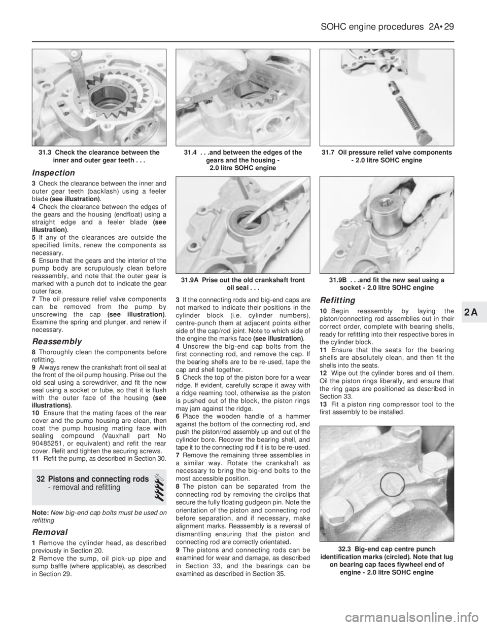
3Check the clearance between the inner and
outer gear teeth (backlash) using a feeler
blade (see illustration).
4Check the clearance between the edges of
the gears and the housing (endfloat) using a
straight edge and a feeler blade (see
illustration).
5If any of the clearances are outside the
specified limits, renew the components as
necessary.
6Ensure that the gears and the interior of the
pump body are scrupulously clean before
reassembly, and note that the outer gear is
marked with a punch dot to indicate the gear
outer face.
7The oil pressure relief valve components
can be removed from the pump by
unscrewing the cap (see illustration).
Examine the spring and plunger, and renew if
necessary.
Reassembly
8Thoroughly clean the components before
refitting.
9Always renew the crankshaft front oil seal at
the front of the oil pump housing. Prise out the
old seal using a screwdriver, and fit the new
seal using a socket or tube, so that it is flush
with the outer face of the housing (see
illustrations).
10Ensure that the mating faces of the rear
cover and the pump housing are clean, then
coat the pump housing mating face with
sealing compound (Vauxhall part No
90485251, or equivalent) and refit the rear
cover. Refit and tighten the securing screws.
11Refit the pump, as described in Section 30.
32Pistons and connecting rods
- removal and refitting
4
Note: New big-end cap bolts must be used on
refitting
Removal
1Remove the cylinder head, as described
previously in Section 20.
2Remove the sump, oil pick-up pipe and
sump baffle (where applicable), as described
in Section 29.3If the connecting rods and big-end caps are
not marked to indicate their positions in the
cylinder block (i.e. cylinder numbers),
centre-punch them at adjacent points either
side of the cap/rod joint. Note to which side of
the engine the marks face (see illustration).
4Unscrew the big-end cap bolts from the
first connecting rod, and remove the cap. If
the bearing shells are to be re-used, tape the
cap and shell together.
5Check the top of the piston bore for a wear
ridge. If evident, carefully scrape it away with
a ridge reaming tool, otherwise as the piston
is pushed out of the block, the piston rings
may jam against the ridge.
6Place the wooden handle of a hammer
against the bottom of the connecting rod, and
push the piston/rod assembly up and out of the
cylinder bore. Recover the bearing shell, and
tape it to the connecting rod if it is to be re-used.
7Remove the remaining three assemblies in
a similar way. Rotate the crankshaft as
necessary to bring the big-end bolts to the
most accessible position.
8The piston can be separated from the
connecting rod by removing the circlips that
secure the fully floating gudgeon pin. Note the
orientation of the piston and connecting rod
before separation, and if necessary, make
alignment marks. Reassembly is a reversal of
dismantling ensuring that the piston and
connecting rod are correctly orientated.
9The pistons and connecting rods can be
examined for wear and damage, as described
in Section 33, and the bearings can be
examined as described in Section 35.
Refitting
10Begin reassembly by laying the
piston/connecting rod assemblies out in their
correct order, complete with bearing shells,
ready for refitting into their respective bores in
the cylinder block.
11Ensure that the seats for the bearing
shells are absolutely clean, and then fit the
shells into the seats.
12Wipe out the cylinder bores and oil them.
Oil the piston rings liberally, and ensure that
the ring gaps are positioned as described in
Section 33.
13Fit a piston ring compressor tool to the
first assembly to be installed.
SOHC engine procedures 2A•29
31.7 Oil pressure relief valve components
- 2.0 litre SOHC engine
32.3 Big-end cap centre punch
identification marks (circled). Note that lug
on bearing cap faces flywheel end of
engine - 2.0 litre SOHC engine
31.9B . . .and fit the new seal using a
socket - 2.0 litre SOHC engine31.9A Prise out the old crankshaft front
oil seal . . .
31.4 . . .and between the edges of the
gears and the housing -
2.0 litre SOHC engine31.3 Check the clearance between the
inner and outer gear teeth . . .
2A