1988 OPEL CALIBRA open bonnet
[x] Cancel search: open bonnetPage 27 of 525
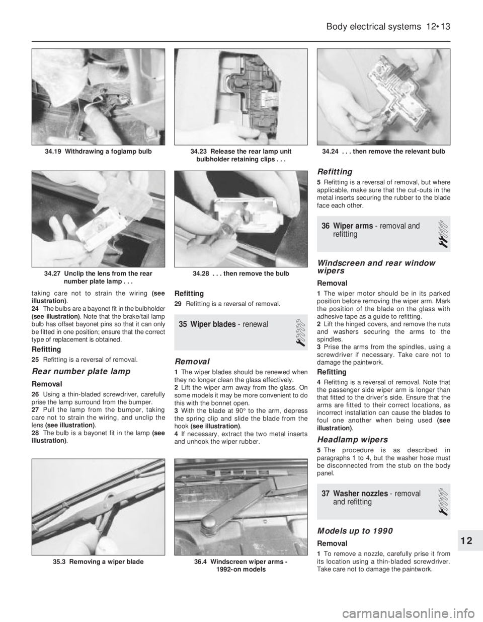
taking care not to strain the wiring (see
illustration).
24The bulbs are a bayonet fit in the bulbholder
(see illustration). Note that the brake/tail lamp
bulb has offset bayonet pins so that it can only
be fitted in one position; ensure that the correct
type of replacement is obtained.
Refitting
25Refitting is a reversal of removal.
Rear number plate lamp
Removal
26Using a thin-bladed screwdriver, carefully
prise the lamp surround from the bumper.
27Pull the lamp from the bumper, taking
care not to strain the wiring, and unclip the
lens (see illustration).
28The bulb is a bayonet fit in the lamp (see
illustration).
Refitting
29Refitting is a reversal of removal.
35Wiper blades -renewal
1
Removal
1The wiper blades should be renewed when
they no longer clean the glass effectively.
2Lift the wiper arm away from the glass. On
some models it may be more convenient to do
this with the bonnet open.
3With the blade at 90°to the arm, depress
the spring clip and slide the blade from the
hook (see illustration).
4If necessary, extract the two metal inserts
and unhook the wiper rubber.
Refitting
5Refitting is a reversal of removal, but where
applicable, make sure that the cut-outs in the
metal inserts securing the rubber to the blade
face each other.
36Wiper arms - removal and
refitting
2
Windscreen and rear window
wipers
Removal
1The wiper motor should be in its parked
position before removing the wiper arm. Mark
the position of the blade on the glass with
adhesive tape as a guide to refitting.
2Lift the hinged covers, and remove the nuts
and washers securing the arms to the
spindles.
3Prise the arms from the spindles, using a
screwdriver if necessary. Take care not to
damage the paintwork.
Refitting
4Refitting is a reversal of removal. Note that
the passenger side wiper arm is longer than
that fitted to the driver’s side. Ensure that the
arms are fitted to their correct locations, as
incorrect installation can cause the blades to
foul one another when being used (see
illustration).
Headlamp wipers
5The procedure is as described in
paragraphs 1 to 4, but the washer hose must
be disconnected from the stub on the body
panel.
37Washer nozzles - removal
and refitting
1
Models up to 1990
Removal
1To remove a nozzle, carefully prise it from
its location using a thin-bladed screwdriver.
Take care not to damage the paintwork.
Body electrical systems 12•13
34.24 . . . then remove the relevant bulb
36.4 Windscreen wiper arms -
1992-on models35.3 Removing a wiper blade
34.28 . . . then remove the bulb34.27 Unclip the lens from the rear
number plate lamp . . .
34.23 Release the rear lamp unit
bulbholder retaining clips . . .34.19 Withdrawing a foglamp bulb
12
Page 91 of 525
28The system also incorporates a separate
ignition amplifier module that transmits
amplified signals from the main system
module to trigger the HT pulse from the
ignition coil. The module is mounted on the
ignition coil’s bracket/baseplate.
29Additionally, the Motronic module
receives information from a cylinder
block-mounted knock sensor, which senses
“knocking” (or pre-ignition) just as it begins to
occur, enabling the module to retard the
ignition timing, thus preventing engine
damage.
Simtec 56.1
30This system uses increased amount of
electronic components instead of mechanical
parts as sensors and actuators with the
Simtec engine management system. This
provides more precise operating data as well
as greater problem free motoring.
31The control unit is equipped with
electronic ignition control. Called ‘Micropro-
cessor Spark Timing System, inductive
triggered’, (or MSTS-i), and means that the
mechanical high voltage distributor is no
longer needed. It is located behind the trim
panel, on the right-hand side footwell (door
pillar).
32The ignition coil is replaced by a dual
spark ignition coil, which is switched directly
by the output stages in the control unit.
33A camshaft sensor will maintain
emergency operation, should the crankshaft
inductive pulse pick-up, malfunction. These
sense TDC (‘Top Dead Centre’), crankshaft
angle and engine speed. The signals are used
by the control unit to calculate ignition point
and for fuel injection.
34The ‘hot film airflow meter’ determines the
mass of air taken in by the engine. The system
uses this information to calculate the correct
amount of fuel needed for injection in the
engine.
35The air inlet temperature sensor (NTC), is
fitted in the air inlet duct between the air
cleaner and the hot mass air flow meter.
36A controlled canister purge valve is
actuated by the system. The tank ventilation is
monitored closely with the Lambda control (or
oxygen sensor) and adaptation by the
computer within the control unit.
37A knock control system is also fitted. This
eliminates the need for octane number
adjustment, as it is performed automatically
through the control unit.
3Electrical system -
precautions
1It is necessary to take extra care when
working on the electrical system, to avoid
damage to semi-conductor devices (diodes
and transistors), and to avoid the risk of
personal injury. Along with the precautions
given in the “Safety first!” Section at the
beginning of this manual, take note of the
following points when working on the system.
2Always remove rings, watches, etc. before
working on the electrical system. Even with
the battery disconnected, discharge could
occur if a component live terminal is earthed
through a metal object. This could cause a
shock or nasty burn.
3Do not reverse the battery connections.
Components such as the alternator, or any
other component having semi-conductor
circuitry, could be irreparably damaged.
4If the engine is being started using jump
leads and a slave battery, connect the
batteries positive to positive and negative to
negative. This also applies when connecting a
battery charger.
5Never disconnect the battery terminals, or
alternator multi-plug connector, when the
engine is running.
6The battery leads and alternator wiring
must be disconnected before carrying out any
electric welding on the vehicle.
7Never use an ohmmeter of the type
incorporating a hand-cranked generator for
circuit or continuity testing.
8Engine management modules are very
sensitive components, and certain
precautions must be taken, to avoid damage
to the module when working on a vehicle
equipped with an engine management
system, as follows.
9When carrying out welding operations on
the vehicle using electric welding equipment,
the battery and alternator should be
disconnected.
10Although underbonnet-mounted modules
will tolerate normal underbonnet conditions,
they can be adversely affected by excess heat
or moisture. If using welding equipment or
pressure washing equipment near the
module, take care not to direct heat, or jets of
water or steam, at the module. If this cannot
be avoided, remove the module from the
vehicle, and protect its wiring plug with a
plastic bag.
11Before disconnecting any wiring, or
removing components, always ensure that the
ignition is switched off.
12Do not attempt to improvise fault
diagnosis procedures using a test lamp or
multimeter, as irreparable damage could be
caused to the module.13After working on ignition/engine
management system components, ensure
that all wiring is correctly reconnected before
reconnecting the battery or switching on the
ignition.
14Any ignition system that uses a
“Hall-effect” generator in the distributor,
cannot be tested. Test equipment that uses
its own power source (e.g. an ohmmeter),
when connected to the distributor or the
“Hall-effect” generator, will be damaged.
4Ignition system testing -
general
3
Note: Refer to Section 3 before proceeding.
Always switch off the ignition before
disconnecting or connecting any component
and when using a multi-meter to check
resistances. Any voltmeter or multi-meter
used to test ignition system components must
have an impedance of 10 meg ohms or
greater
1Electronic ignition system components are
normally very reliable. Most faults are far more
likely to be due to loose or dirty connections,
or to “tracking” of HT voltage due to dirt,
dampness or damaged insulation than to
component failure. Always check all wiring
thoroughly before condemning an electrical
component and work methodically to
eliminate all other possibilities before deciding
that a particular component is faulty.
2The old practice of checking for a spark by
holding the live end of a HT lead a short
distance away from the engine is not
recommended. Not only is there a high risk of
a powerful electric shock, but the ignition coil
or amplifier module will be damaged.
Similarly, never try to “diagnose” misfires by
pulling off one HT lead at a time. Note also
that the ECU is at risk if the system is
triggered with an open (i.e., not properly
earthed) HT circuit; ECU’s are very expensive
to replace, so take care!
3If you are in any doubt as to your skill and
ability to test an ignition system component or
if you do not have the required equipment,
take the vehicle to a suitably equipped
Vauxhall dealer. It is better to pay the labour
charges involved in having the vehicle
checked by an expert than to risk damage to
the system or to yourself.
4If the engine either will not turn over at all,
or only turns very slowly, check the battery
and starter motor. Connect a voltmeter across
the battery terminals (meter positive probe to
battery positive terminal) and disconnect the
ignition coil HT lead from the distributor cap
and earth. Note the voltage reading obtained
while turning over the engine on the starter for
(no more than) ten seconds. If the reading
obtained is less than approximately 9.5 volts,
check the battery, battery connections, starter
motor and charging system.
5•4Engine electrical systems
Warning: The HT voltage
generated by an electronic
ignition system is extremely
high and, in certain
circumstances, could prove fatal. Take
care to avoid receiving electric shocks
from the HT side of the ignition system.
Do not handle HT leads, or touch the
distributor or coil, when the engine is
running. If tracing faults in the HT circuit,
use well-insulated tools to manipulate live
leads
Page 107 of 525
6Bonnet - removal and refitting
2
Removal
1Open the bonnet, and support it in the fully
open position.
2On models fitted with an underbonnet lamp,
disconnect the battery negative lead, then
prise the lamp from the bonnet and disconnect
the wiring. If the bonnet is to be refitted, to aid
routing of the wiring on refitting, tie a length of
string to the end of the wiring. Then withdraw
the wiring through the bonnet and untie the
string, leaving it in position in the bonnet.
3Similarly, disconnect the windscreen
washer fluid hose from the connector in the
bonnet, but tie the string to the connector, to
prevent it from slipping into an inaccessible
position in the bonnet.
4Mark the position of the hinges on the
bonnet.
5With the help of an assistant, support the
weight of the bonnet, then unscrew the
securing bolts from the hinges, and lift the
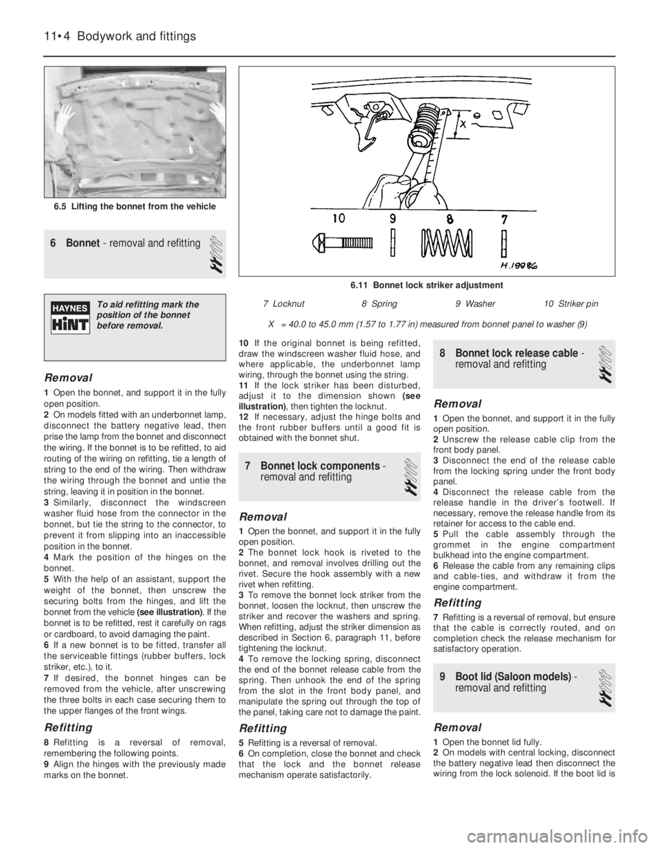
bonnet from the vehicle (see illustration). If the
bonnet is to be refitted, rest it carefully on rags
or cardboard, to avoid damaging the paint.
6If a new bonnet is to be fitted, transfer all
the serviceable fittings (rubber buffers, lock
striker, etc.), to it.
7If desired, the bonnet hinges can be
removed from the vehicle, after unscrewing
the three bolts in each case securing them to
the upper flanges of the front wings.
Refitting
8Refitting is a reversal of removal,
remembering the following points.
9Align the hinges with the previously made
marks on the bonnet.10If the original bonnet is being refitted,
draw the windscreen washer fluid hose, and
where applicable, the underbonnet lamp
wiring, through the bonnet using the string.
11If the lock striker has been disturbed,
adjust it to the dimension shown (see
illustration), then tighten the locknut.
12If necessary, adjust the hinge bolts and
the front rubber buffers until a good fit is
obtained with the bonnet shut.
7Bonnet lock components -
removal and refitting
2
Removal
1Open the bonnet, and support it in the fully
open position.
2The bonnet lock hook is riveted to the
bonnet, and removal involves drilling out the
rivet. Secure the hook assembly with a new
rivet when refitting.
3To remove the bonnet lock striker from the
bonnet, loosen the locknut, then unscrew the
striker and recover the washers and spring.
When refitting, adjust the striker dimension as
described in Section 6, paragraph 11, before
tightening the locknut.
4To remove the locking spring, disconnect
the end of the bonnet release cable from the
spring. Then unhook the end of the spring
from the slot in the front body panel, and
manipulate the spring out through the top of
the panel, taking care not to damage the paint.
Refitting
5Refitting is a reversal of removal.
6On completion, close the bonnet and check
that the lock and the bonnet release
mechanism operate satisfactorily.
8Bonnet lock release cable -
removal and refitting
2
Removal
1Open the bonnet, and support it in the fully
open position.
2Unscrew the release cable clip from the
front body panel.
3Disconnect the end of the release cable
from the locking spring under the front body
panel.
4Disconnect the release cable from the
release handle in the driver’s footwell. If
necessary, remove the release handle from its
retainer for access to the cable end.
5Pull the cable assembly through the
grommet in the engine compartment
bulkhead into the engine compartment.
6Release the cable from any remaining clips
and cable-ties, and withdraw it from the
engine compartment.
Refitting
7Refitting is a reversal of removal, but ensure
that the cable is correctly routed, and on
completion check the release mechanism for
satisfactory operation.
9Boot lid (Saloon models) -
removal and refitting
2
Removal
1Open the bonnet lid fully.
2On models with central locking, disconnect
the battery negative lead then disconnect the
wiring from the lock solenoid. If the boot lid is
11•4Bodywork and fittings
6.5 Lifting the bonnet from the vehicle
6.11 Bonnet lock striker adjustment
X = 40.0 to 45.0 mm (1.57 to 1.77 in) measured from bonnet panel to washer (9)
7 Locknut8 Spring9 Washer10 Striker pinTo aid refitting mark the
position of the bonnet
before removal.
Page 115 of 525
6Carefully withdraw the bumper from the
vehicle.
Refitting
7Refitting is a reversal of removal.
Rear bumper
Removal
8Remove the rear trim panel from the
luggage compartment by prising up the top
edge to release the clips, then lift the panel
upwards to free it from the lower locating
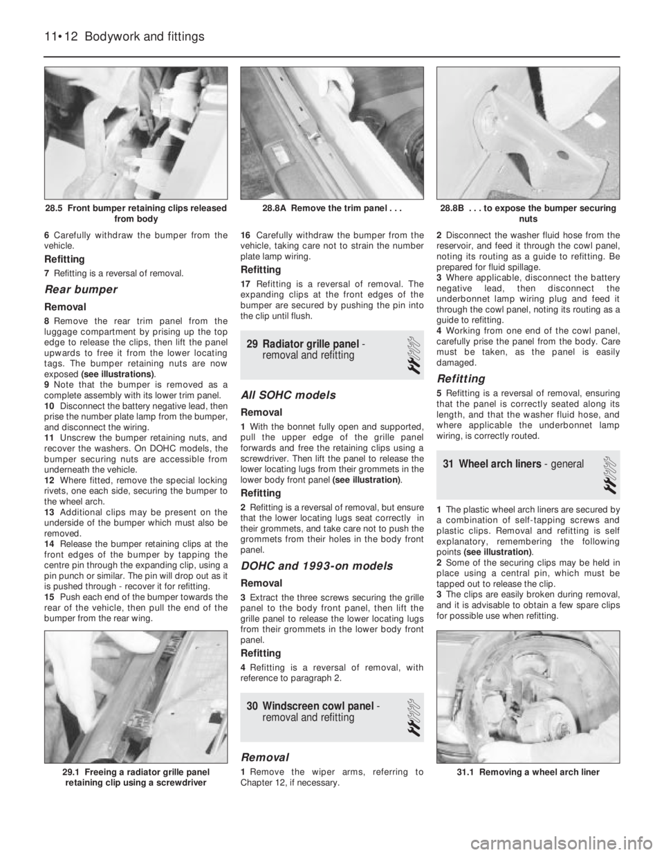
tags. The bumper retaining nuts are now
exposed (see illustrations).
9Note that the bumper is removed as a
complete assembly with its lower trim panel.
10Disconnect the battery negative lead, then
prise the number plate lamp from the bumper,
and disconnect the wiring.
11Unscrew the bumper retaining nuts, and
recover the washers. On DOHC models, the
bumper securing nuts are accessible from
underneath the vehicle.
12Where fitted, remove the special locking
rivets, one each side, securing the bumper to
the wheel arch.
13Additional clips may be present on the
underside of the bumper which must also be
removed.
14Release the bumper retaining clips at the
front edges of the bumper by tapping the
centre pin through the expanding clip, using a
pin punch or similar. The pin will drop out as it
is pushed through - recover it for refitting.
15Push each end of the bumper towards the
rear of the vehicle, then pull the end of the
bumper from the rear wing.16Carefully withdraw the bumper from the
vehicle, taking care not to strain the number
plate lamp wiring.
Refitting
17Refitting is a reversal of removal. The
expanding clips at the front edges of the
bumper are secured by pushing the pin into
the clip until flush.
29Radiator grille panel -
removal and refitting
2
All SOHC models
Removal
1With the bonnet fully open and supported,
pull the upper edge of the grille panel
forwards and free the retaining clips using a
screwdriver. Then lift the panel to release the
lower locating lugs from their grommets in the
lower body front panel (see illustration).
Refitting
2Refitting is a reversal of removal, but ensure
that the lower locating lugs seat correctly in
their grommets, and take care not to push the
grommets from their holes in the body front
panel.
DOHC and 1993-on models
Removal
3Extract the three screws securing the grille
panel to the body front panel, then lift the
grille panel to release the lower locating lugs
from their grommets in the lower body front
panel.
Refitting
4Refitting is a reversal of removal, with
reference to paragraph 2.
30Windscreen cowl panel -
removal and refitting
2
Removal
1Remove the wiper arms, referring to
Chapter 12, if necessary.2Disconnect the washer fluid hose from the
reservoir, and feed it through the cowl panel,
noting its routing as a guide to refitting. Be
prepared for fluid spillage.
3Where applicable, disconnect the battery
negative lead, then disconnect the
underbonnet lamp wiring plug and feed it
through the cowl panel, noting its routing as a
guide to refitting.
4Working from one end of the cowl panel,
carefully prise the panel from the body. Care
must be taken, as the panel is easily
damaged.
Refitting
5Refitting is a reversal of removal, ensuring
that the panel is correctly seated along its
length, and that the washer fluid hose, and
where applicable the underbonnet lamp
wiring, is correctly routed.
31Wheel arch liners - general
2
1The plastic wheel arch liners are secured by
a combination of self-tapping screws and
plastic clips. Removal and refitting is self
explanatory, remembering the following
points (see illustration).
2Some of the securing clips may be held in
place using a central pin, which must be
tapped out to release the clip.
3The clips are easily broken during removal,
and it is advisable to obtain a few spare clips
for possible use when refitting.
11•12Bodywork and fittings
28.8B . . . to expose the bumper securing
nuts
31.1 Removing a wheel arch liner29.1 Freeing a radiator grille panel
retaining clip using a screwdriver
28.8A Remove the trim panel . . .28.5 Front bumper retaining clips released
from body
Page 139 of 525
5If any one of the shoes has worn below the
specified limit, all four handbrake shoes must
be renewed as a set, as follows.
SOHC models
Removal
6Clean the dust and dirt from the various
components, but take care not to inhale it.
7Disconnect the handbrake cable and the
return spring from the handbrake operating
lever at the brake backplate. If necessary,
slacken the handbrake cable adjustment, with
reference to Section 26.
8Remove the shoe hold-down pins, springs
and cups by depressing the cups and turning
them through 90°using a pair of pliers. Note
that the hold-down pins are removed through
the rear of the brake backplate.
9The shoes, adjuster, handbrake operating
lever and return springs can now be removed
together as an assembly.
10Note the position and orientation of all
components, then unhook the upper and
lower return springs from the shoes, and
recover the handbrake operating lever and the
adjuster.
Refitting
11Apply a little brake grease to the threads
of the adjuster, then screw it together to its
minimum length. Also apply a little brake
grease to the shoe rubbing areas on the
lockplate.
12Fit one of the new brake shoes, and
secure it to the backplate with the hold-down
pin, spring and cup.
13Fit the handbrake operating lever in
position.
14Fit the remaining brake shoe, and secure
with the hold-down pin, spring and cup.
15Hook the upper return spring onto the
shoes.
16Fit the adjuster between the lower ends of
the shoes, as noted before dismantling, then
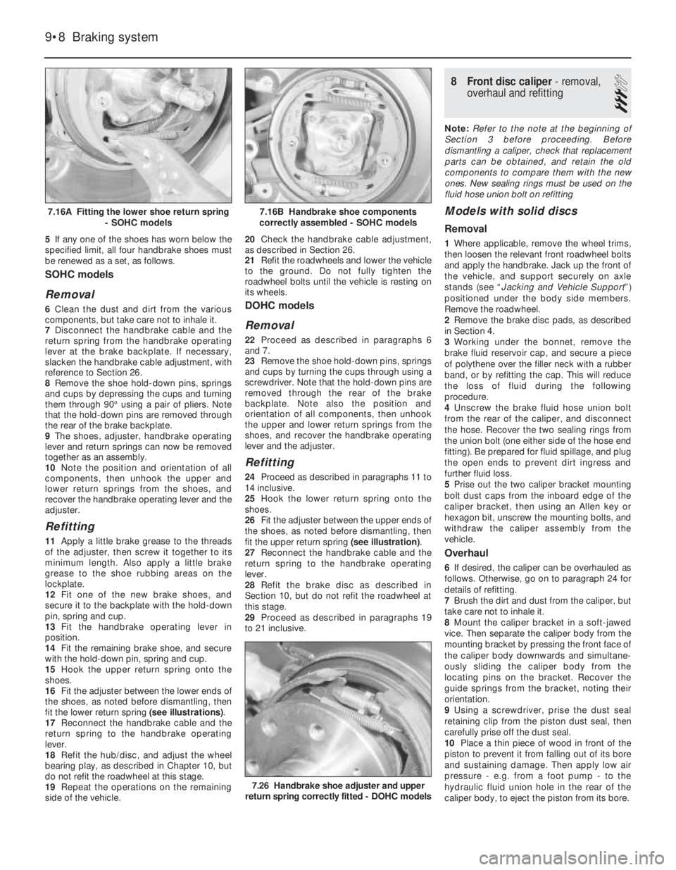
fit the lower return spring (see illustrations).
17Reconnect the handbrake cable and the
return spring to the handbrake operating
lever.
18Refit the hub/disc, and adjust the wheel
bearing play, as described in Chapter 10, but
do not refit the roadwheel at this stage.
19Repeat the operations on the remaining
side of the vehicle.20Check the handbrake cable adjustment,
as described in Section 26.
21Refit the roadwheels and lower the vehicle
to the ground. Do not fully tighten the
roadwheel bolts until the vehicle is resting on
its wheels.
DOHC models
Removal
22Proceed as described in paragraphs 6
and 7.
23Remove the shoe hold-down pins, springs
and cups by turning the cups through using a
screwdriver. Note that the hold-down pins are
removed through the rear of the brake
backplate. Note also the position and
orientation of all components, then unhook
the upper and lower return springs from the
shoes, and recover the handbrake operating
lever and the adjuster.
Refitting
24Proceed as described in paragraphs 11 to
14 inclusive.
25Hook the lower return spring onto the
shoes.
26Fit the adjuster between the upper ends of
the shoes, as noted before dismantling, then
fit the upper return spring (see illustration).
27Reconnect the handbrake cable and the
return spring to the handbrake operating
lever.
28Refit the brake disc as described in
Section 10, but do not refit the roadwheel at
this stage.
29Proceed as described in paragraphs 19
to 21 inclusive.
8Front disc caliper - removal,
overhaul and refitting
3
Note: Refer to the note at the beginning of
Section 3 before proceeding. Before
dismantling a caliper, check that replacement
parts can be obtained, and retain the old
components to compare them with the new
ones. New sealing rings must be used on the
fluid hose union bolt on refitting
Models with solid discs
Removal
1Where applicable, remove the wheel trims,
then loosen the relevant front roadwheel bolts
and apply the handbrake. Jack up the front of
the vehicle, and support securely on axle
stands (see “Jacking and Vehicle Support”)
positioned under the body side members.
Remove the roadwheel.
2Remove the brake disc pads, as described
in Section 4.
3Working under the bonnet, remove the
brake fluid reservoir cap, and secure a piece
of polythene over the filler neck with a rubber
band, or by refitting the cap. This will reduce
the loss of fluid during the following
procedure.
4Unscrew the brake fluid hose union bolt
from the rear of the caliper, and disconnect
the hose. Recover the two sealing rings from
the union bolt (one either side of the hose end
fitting). Be prepared for fluid spillage, and plug
the open ends to prevent dirt ingress and
further fluid loss.
5Prise out the two caliper bracket mounting
bolt dust caps from the inboard edge of the
caliper bracket, then using an Allen key or
hexagon bit, unscrew the mounting bolts, and
withdraw the caliper assembly from the
vehicle.
Overhaul
6If desired, the caliper can be overhauled as
follows. Otherwise, go on to paragraph 24 for
details of refitting.
7Brush the dirt and dust from the caliper, but
take care not to inhale it.
8Mount the caliper bracket in a soft-jawed
vice. Then separate the caliper body from the
mounting bracket by pressing the front face of
the caliper body downwards and simultane-
ously sliding the caliper body from the
locating pins on the bracket. Recover the
guide springs from the bracket, noting their
orientation.
9Using a screwdriver, prise the dust seal
retaining clip from the piston dust seal, then
carefully prise off the dust seal.
10Place a thin piece of wood in front of the
piston to prevent it from falling out of its bore
and sustaining damage. Then apply low air
pressure - e.g. from a foot pump - to the
hydraulic fluid union hole in the rear of the
caliper body, to eject the piston from its bore.
9•8Braking system
7.16A Fitting the lower shoe return spring
- SOHC models
7.26 Handbrake shoe adjuster and upper
return spring correctly fitted - DOHC models
7.16B Handbrake shoe components
correctly assembled - SOHC models
Page 140 of 525
11Remove the wood and carefully withdraw
the piston.
12Carefully prise the seal from the groove in
the caliper piston bore, using a plastic or
wooden instrument.
13Inspect the surfaces of the piston and its
bore in the caliper for scoring, or evidence of
metal-to-metal contact. If evident, renew the
complete caliper assembly.
14If the piston and bore are in good
condition, discard the seals and obtain a
repair kit, which will contain all the necessary
renewable items.
15Clean the piston and cylinder bore with
brake fluid or methylated spirit, nothing else!
16Begin reassembly by fitting the seal into
the caliper bore.
17Locate the dust seal in its groove in the
piston. Dip the piston in clean brake fluid and
insert it squarely into the cylinder. Check that
the cutaway recesses in the piston are
positioned horizontally. If necessary, carefully
turn the piston to its correct position.
18When the piston has been partially
depressed, engage the dust seal with the rim
of the caliper bore, and fit the retaining clip.
19Push the piston further into its bore, but
not as far as the stop, ensuring that it does
not jam.
20If desired, the caliper body locating pin
rubbers can be renewed. Extract the nylon
compression sleeve from within each rubber,
then carefully compress the rubber shoulder,
and push the rubber through the hole in the
caliper body to remove it from the inboard
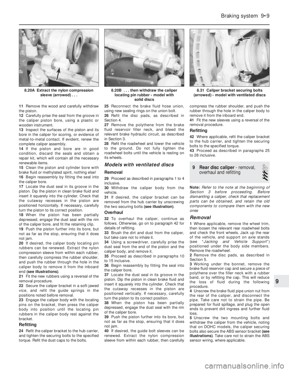
end (see illustrations).
21Fit the new rubbers using a reversal of the
removal procedure.
22Secure the caliper bracket in a soft-jawed
vice, and refit the guide springs in the
positions noted before removal.
23Engage the caliper body with the locating
pins on the bracket, then press the caliper
body into position until the locating pin
rubbers in the caliper body rest against the
bracket.
Refitting
24Refit the caliper bracket to the hub carrier,
and tighten the securing bolts to the specified
torque. Refit the dust caps to the bolts.25Reconnect the brake fluid hose union,
using new sealing rings on the union bolt.
26Refit the disc pads, as described in
Section 4.
27Remove the polythene from the brake
fluid reservoir filler neck, and bleed the
relevant brake hydraulic circuit, as described
in Section 3.
28Refit the roadwheel and lower the vehicle
to the ground. Do not fully tighten the
roadwheel bolts until the vehicle is resting on
its wheels.
Models with ventilated discs
Removal
29Proceed as described in paragraphs 1 to 4
inclusive.
30Withdraw the caliper body from the
vehicle.
31If desired, the caliper bracket can be
removed from the hub carrier by unscrewing
the two securing bolts (see illustration).
Overhaul
32To overhaul the caliper, continue as
follows. Otherwise, go on to paragraph 42 for
details of refitting.
33Brush the dirt and dust from the caliper,
but take care not to inhale it.
34Using a screwdriver, carefully prise the
dust seal from the end of the piston and the
caliper body, and remove it.
35Proceed as described in paragraphs 10
to 15 inclusive.
36Begin reassembly by fitting the seal into
the caliper bore.
37Locate the dust seal in its groove in the
piston. Dip the piston in clean brake fluid and
insert it squarely into the cylinder. Check that
the cutaway recesses in the piston are
positioned vertically. If necessary, carefully
turn the piston to its correct position.
38When the piston has been partially
depressed, engage the dust seal with the rim
of the caliper bore.
39Push the piston further into its bore, but
not as far as the stop, ensuring that it does
not jam.
40If desired, the guide bolt sleeves can be
renewed. Extract the nylon compression
sleeve from within each rubber, then carefullycompress the rubber shoulder, and push the
rubber through the hole in the caliper body to
remove it from the inboard end.
41Fit the new sleeves using a reversal of the
removal procedure.
Refitting
42Where applicable, refit the caliper bracket
to the hub carrier, and tighten the securing
bolts to the specified torque.
43Proceed as described in paragraphs 25
to 28 inclusive.
9Rear disc caliper - removal,
overhaul and refitting
3
Note: Refer to the note at the beginning of
Section 3 before proceeding. Before
dismantling a caliper, check that replacement
parts can be obtained, and retain the old
components to compare them with the new
ones
Removal
1Where applicable, remove the wheel trim,
then loosen the relevant rear roadwheel bolts
and check the front wheels. Jack up the rear
of the vehicle, and support on axle stands
(see “Jacking and Vehicle Support”)
positioned under the body side members.
Remove the roadwheel.
2Remove the disc pads, as described in
Section 5.
3Working under the bonnet, remove the
brake fluid reservoir cap and secure a piece of
polythene over the filler neck with a rubber
band, or by refitting the cap. This will reduce
the loss of fluid during the following
procedure.
4Unscrew the brake fluid pipe union nut from
the rear of the caliper, and disconnect the
pipe. Take care not to strain the pipe. Be
prepared for fluid spillage, and plug the open
ends to prevent dirt ingress and further fluid
loss.
5Unscrew the two mounting bolts and
withdraw the caliper from the vehicle, noting
that on DOHC models, the caliper securing
bolts also secure the ABS sensor bracket (see
illustrations). Take care not to strain the ABS
sensor wiring, where applicable.
Braking system 9•9
8.31 Caliper bracket securing bolts
(arrowed) - model with ventilated discs8.20B . . . then withdraw the caliper
locating pin rubber - model with
solid discs8.20A Extract the nylon compression
sleeve (arrowed) . . .
9
Page 142 of 525
Rear disc - DOHC models
Removal
15Where applicable, remove the roadwheel
bolt and spacer used when checking the disc.
16Remove the disc pads, as described in
Section 5.
17Remove the brake caliper with reference
to Section 9, but leave the hydraulic fluid pipe
connected. Move the caliper to one side, and
suspend it using wire or string to avoid
straining the pipe.
18Remove the securing screw and withdraw
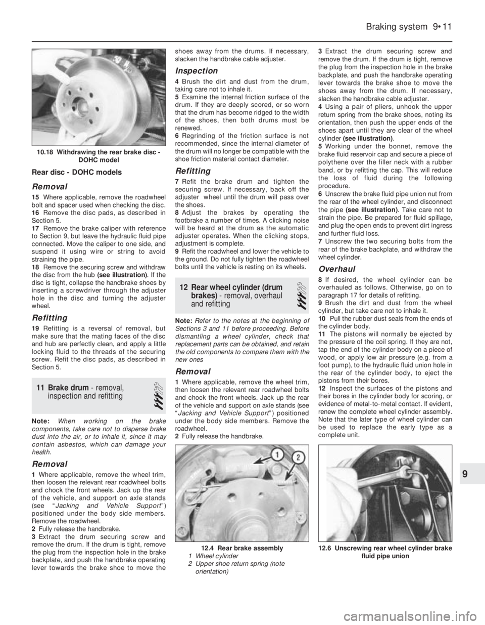
the disc from the hub (see illustration). If the
disc is tight, collapse the handbrake shoes by
inserting a screwdriver through the adjuster
hole in the disc and turning the adjuster
wheel.
Refitting
19Refitting is a reversal of removal, but
make sure that the mating faces of the disc
and hub are perfectly clean, and apply a little
locking fluid to the threads of the securing
screw. Refit the disc pads, as described in
Section 5.
11Brake drum - removal,
inspection and refitting
3
Note: When working on the brake
components, take care not to disperse brake
dust into the air, or to inhale it, since it may
contain asbestos, which can damage your
health.
Removal
1Where applicable, remove the wheel trim,
then loosen the relevant rear roadwheel bolts
and chock the front wheels. Jack up the rear
of the vehicle, and support on axle stands
(see “Jacking and Vehicle Support”)
positioned under the body side members.
Remove the roadwheel.
2Fully release the handbrake.
3Extract the drum securing screw and
remove the drum. If the drum is tight, remove
the plug from the inspection hole in the brake
backplate, and push the handbrake operating
lever towards the brake shoe to move theshoes away from the drums. If necessary,
slacken the handbrake cable adjuster.
Inspection
4Brush the dirt and dust from the drum,
taking care not to inhale it.
5Examine the internal friction surface of the
drum. If they are deeply scored, or so worn
that the drum has become ridged to the width
of the shoes, then both drums must be
renewed.
6Regrinding of the friction surface is not
recommended, since the internal diameter of
the drum will no longer be compatible with the
shoe friction material contact diameter.
Refitting
7Refit the brake drum and tighten the
securing screw. If necessary, back off the
adjuster wheel until the drum will pass over
the shoes.
8Adjust the brakes by operating the
footbrake a number of times. A clicking noise
will be heard at the drum as the automatic
adjuster operates. When the clicking stops,
adjustment is complete.
9Refit the roadwheel and lower the vehicle to
the ground. Do not fully tighten the roadwheel
bolts until the vehicle is resting on its wheels.
12Rear wheel cylinder (drum
brakes) - removal, overhaul
and refitting
3
Note: Refer to the notes at the beginning of
Sections 3 and 11 before proceeding. Before
dismantling a wheel cylinder, check that
replacement parts can be obtained, and retain
the old components to compare them with the
new ones
Removal
1Where applicable, remove the wheel trim,
then loosen the relevant rear roadwheel bolts
and chock the front wheels. Jack up the rear
of the vehicle and support on axle stands (see
“Jacking and Vehicle Support”) positioned
under the body side members. Remove the
roadwheel.
2Fully release the handbrake.3Extract the drum securing screw and
remove the drum. If the drum is tight, remove
the plug from the inspection hole in the brake
backplate, and push the handbrake operating
lever towards the brake shoe to move the
shoes away from the drum. If necessary,
slacken the handbrake cable adjuster.
4Using a pair of pliers, unhook the upper
return spring from the brake shoes, noting its
orientation, then push the upper ends of the
shoes apart until they are clear of the wheel
cylinder (see illustration).
5Working under the bonnet, remove the
brake fluid reservoir cap and secure a piece of
polythene over the filler neck with a rubber
band, or by refitting the cap. This will reduce
the loss of fluid during the following
procedure.
6Unscrew the brake fluid pipe union nut from
the rear of the wheel cylinder, and disconnect
the pipe (see illustration). Take care not to
strain the pipe. Be prepared for fluid spillage,
and plug the open ends to prevent dirt ingress
and further fluid loss.
7Unscrew the two securing bolts from the
rear of the brake backplate, and withdraw the
wheel cylinder.
Overhaul
8If desired, the wheel cylinder can be
overhauled as follows. Otherwise, go on to
paragraph 17 for details of refitting.
9Brush the dirt and dust from the wheel
cylinder, but take care not to inhale it.
10Pull the rubber dust seals from the ends of
the cylinder body.
11The pistons will normally be ejected by
the pressure of the coil spring. If they are not,
tap the end of the cylinder body on a piece of
wood, or apply low air pressure (e.g. from a
foot pump), to the hydraulic fluid union hole in
the rear of the cylinder body, to eject the
pistons from their bores.
12Inspect the surfaces of the pistons and
their bores in the cylinder body for scoring, or
evidence of metal-to-metal contact. If evident,
renew the complete wheel cylinder assembly.
Note that the later type of wheel cylinder can
be used to replace the early type as a
complete unit.
Braking system 9•11
12.6 Unscrewing rear wheel cylinder brake
fluid pipe union12.4 Rear brake assembly
1 Wheel cylinder
2 Upper shoe return spring (note
orientation)
10.18 Withdrawing the rear brake disc -
DOHC model
9
Page 182 of 525
At the same time, check the general
condition of the CV joints themselves by first
holding the driveshaft and attempting to
rotate the wheel. Repeat this check by holding
the inner joint and attempting to rotate the
driveshaft. Any appreciable movement
indicates wear in the joints, wear in the
driveshaft splines, or a loose driveshaft
retaining nut.
7Automatic transmission fluid
level check
2
Note: The transmission fluid level can be
checked either when it is cold (only below
35ºC (100ºF) outside temperature) or when it is
fully warmed up to normal operating
temperature (after driving for a distance of
approximately 12 miles/20 km). Since the fluid
level must be checked with the engine
running, ensure that the vehicle is parked on
level ground with the handbrake firmly applied
before leaving the driver’s seat. Be careful to
keep loose clothing, long hair, etc., well clear
of hot or moving components when working
under the bonnet
Transmission cold
1Park the vehicle on level ground and apply
the handbrake firmly. With the engine running
at no more than idle speed and your foot
firmly on the brake pedal, move the selector
lever through all positions, ending in position
“P”. Allow the engine to idle for one minute,
then check the level within two minutes.
2With the engine still idling and position “P”
still selected, open the bonnet and withdraw
the transmission dipstick from the filler tube
located in the front of the transmission casing,
at the left-hand end of the engine.
3Note the fluid’s condition (see below), then
wipe clean the dipstick using a clean,
non-fluffy rag, insert it fully back into the tube
and withdraw it again.
4The level should be up to the “MAX” mark
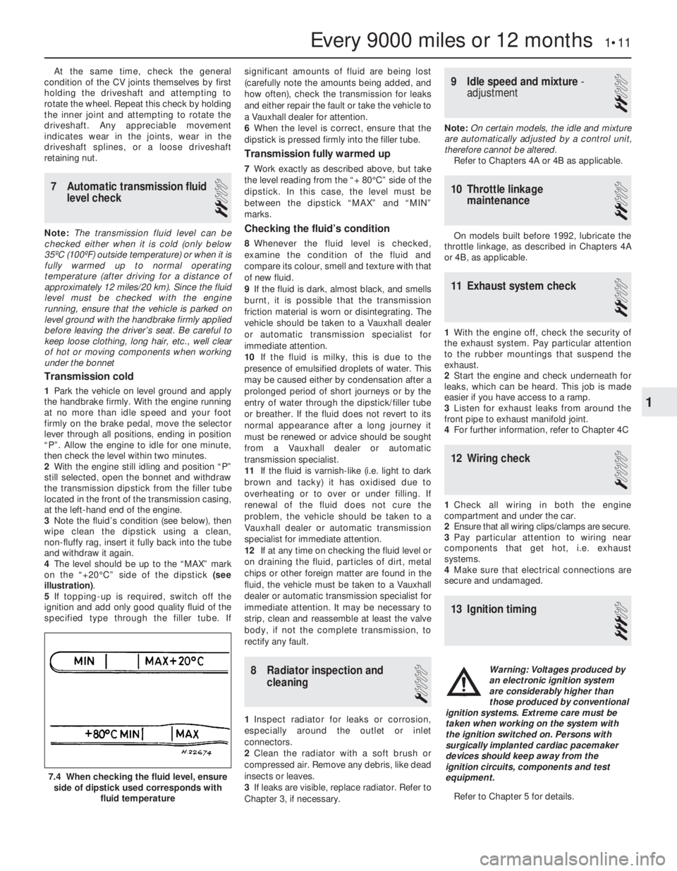
on the “+20°C” side of the dipstick (see
illustration).
5If topping-up is required, switch off the
ignition and add only good quality fluid of the
specified type through the filler tube. Ifsignificant amounts of fluid are being lost
(carefully note the amounts being added, and
how often), check the transmission for leaks
and either repair the fault or take the vehicle to
a Vauxhall dealer for attention.
6When the level is correct, ensure that the
dipstick is pressed firmly into the filler tube.
Transmission fully warmed up
7Work exactly as described above, but take
the level reading from the “+ 80°C” side of the
dipstick. In this case, the level must be
between the dipstick “MAX” and “MIN”
marks.
Checking the fluid’s condition
8Whenever the fluid level is checked,
examine the condition of the fluid and
compare its colour, smell and texture with that
of new fluid.
9If the fluid is dark, almost black, and smells
burnt, it is possible that the transmission
friction material is worn or disintegrating. The
vehicle should be taken to a Vauxhall dealer
or automatic transmission specialist for
immediate attention.
10If the fluid is milky, this is due to the
presence of emulsified droplets of water. This
may be caused either by condensation after a
prolonged period of short journeys or by the
entry of water through the dipstick/filler tube
or breather. If the fluid does not revert to its
normal appearance after a long journey it
must be renewed or advice should be sought
from a Vauxhall dealer or automatic
transmission specialist.
11If the fluid is varnish-like (i.e. light to dark
brown and tacky) it has oxidised due to
overheating or to over or under filling. If
renewal of the fluid does not cure the
problem, the vehicle should be taken to a
Vauxhall dealer or automatic transmission
specialist for immediate attention.
12If at any time on checking the fluid level or
on draining the fluid, particles of dirt, metal
chips or other foreign matter are found in the
fluid, the vehicle must be taken to a Vauxhall
dealer or automatic transmission specialist for
immediate attention. It may be necessary to
strip, clean and reassemble at least the valve
body, if not the complete transmission, to
rectify any fault.
8Radiator inspection and
cleaning
1
1Inspect radiator for leaks or corrosion,
especially around the outlet or inlet
connectors.
2Clean the radiator with a soft brush or
compressed air. Remove any debris, like dead
insects or leaves.
3If leaks are visible, replace radiator. Refer to
Chapter 3, if necessary.
9Idle speed and mixture -
adjustment
2
Note: On certain models, the idle and mixture
are automatically adjusted by a control unit,
therefore cannot be altered.
Refer to Chapters 4A or 4B as applicable.
10Throttle linkage
maintenance
2
On models built before 1992, lubricate the
throttle linkage, as described in Chapters 4A
or 4B, as applicable.
11Exhaust system check
2
1With the engine off, check the security of
the exhaust system. Pay particular attention
to the rubber mountings that suspend the
exhaust.
2Start the engine and check underneath for
leaks, which can be heard. This job is made
easier if you have access to a ramp.
3Listen for exhaust leaks from around the
front pipe to exhaust manifold joint.
4For further information, refer to Chapter 4C
12Wiring check
1
1Check all wiring in both the engine
compartment and under the car.
2Ensure that all wiring clips/clamps are secure.
3Pay particular attention to wiring near
components that get hot, i.e. exhaust
systems.
4Make sure that electrical connections are
secure and undamaged.
13Ignition timing
3
Refer to Chapter 5 for details.
Every 9000 miles or 12 months 1•11
7.4 When checking the fluid level, ensure
side of dipstick used corresponds with
fluid temperature
1
Warning: Voltages produced by
an electronic ignition system
are considerably higher than
those produced by conventional
ignition systems. Extreme care must be
taken when working on the system with
the ignition switched on. Persons with
surgically implanted cardiac pacemaker
devices should keep away from the
ignition circuits, components and test
equipment.