1988 OPEL CALIBRA washer
[x] Cancel search: washerPage 115 of 525
6Carefully withdraw the bumper from the
vehicle.
Refitting
7Refitting is a reversal of removal.
Rear bumper
Removal
8Remove the rear trim panel from the
luggage compartment by prising up the top
edge to release the clips, then lift the panel
upwards to free it from the lower locating
tags. The bumper retaining nuts are now
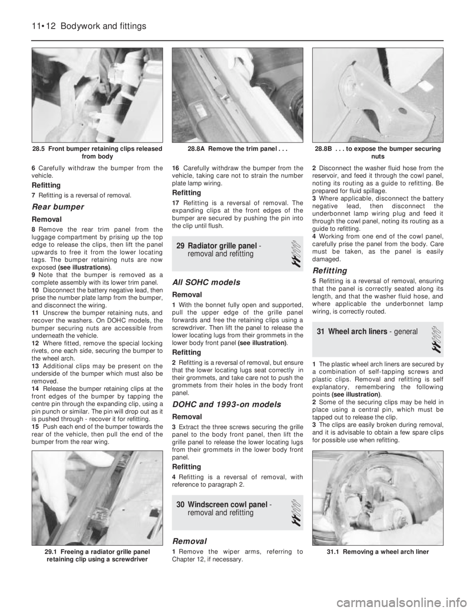
exposed (see illustrations).
9Note that the bumper is removed as a
complete assembly with its lower trim panel.
10Disconnect the battery negative lead, then
prise the number plate lamp from the bumper,
and disconnect the wiring.
11Unscrew the bumper retaining nuts, and
recover the washers. On DOHC models, the
bumper securing nuts are accessible from
underneath the vehicle.
12Where fitted, remove the special locking
rivets, one each side, securing the bumper to
the wheel arch.
13Additional clips may be present on the
underside of the bumper which must also be
removed.
14Release the bumper retaining clips at the
front edges of the bumper by tapping the
centre pin through the expanding clip, using a
pin punch or similar. The pin will drop out as it
is pushed through - recover it for refitting.
15Push each end of the bumper towards the
rear of the vehicle, then pull the end of the
bumper from the rear wing.16Carefully withdraw the bumper from the
vehicle, taking care not to strain the number
plate lamp wiring.
Refitting
17Refitting is a reversal of removal. The
expanding clips at the front edges of the
bumper are secured by pushing the pin into
the clip until flush.
29Radiator grille panel -
removal and refitting
2
All SOHC models
Removal
1With the bonnet fully open and supported,
pull the upper edge of the grille panel
forwards and free the retaining clips using a
screwdriver. Then lift the panel to release the
lower locating lugs from their grommets in the
lower body front panel (see illustration).
Refitting
2Refitting is a reversal of removal, but ensure
that the lower locating lugs seat correctly in
their grommets, and take care not to push the
grommets from their holes in the body front
panel.
DOHC and 1993-on models
Removal
3Extract the three screws securing the grille
panel to the body front panel, then lift the
grille panel to release the lower locating lugs
from their grommets in the lower body front
panel.
Refitting
4Refitting is a reversal of removal, with
reference to paragraph 2.
30Windscreen cowl panel -
removal and refitting
2
Removal
1Remove the wiper arms, referring to
Chapter 12, if necessary.2Disconnect the washer fluid hose from the
reservoir, and feed it through the cowl panel,
noting its routing as a guide to refitting. Be
prepared for fluid spillage.
3Where applicable, disconnect the battery
negative lead, then disconnect the
underbonnet lamp wiring plug and feed it
through the cowl panel, noting its routing as a
guide to refitting.
4Working from one end of the cowl panel,
carefully prise the panel from the body. Care
must be taken, as the panel is easily
damaged.
Refitting
5Refitting is a reversal of removal, ensuring
that the panel is correctly seated along its
length, and that the washer fluid hose, and
where applicable the underbonnet lamp
wiring, is correctly routed.
31Wheel arch liners - general
2
1The plastic wheel arch liners are secured by
a combination of self-tapping screws and
plastic clips. Removal and refitting is self
explanatory, remembering the following
points (see illustration).
2Some of the securing clips may be held in
place using a central pin, which must be
tapped out to release the clip.
3The clips are easily broken during removal,
and it is advisable to obtain a few spare clips
for possible use when refitting.
11•12Bodywork and fittings
28.8B . . . to expose the bumper securing
nuts
31.1 Removing a wheel arch liner29.1 Freeing a radiator grille panel
retaining clip using a screwdriver
28.8A Remove the trim panel . . .28.5 Front bumper retaining clips released
from body
Page 116 of 525
4Certain models may have additional
underbody shields and splashguards fitted,
which may be attached to the wheel arch liners.
32Engine undershield (DOHC
models) - removal and
refitting
2
Removal
1Apply the handbrake, then jack up the front
of the vehicle, and support on axle stands
(see “Jacking and Vehicle Support”).
2Extract the two securing screws, and
remove the oil filter access panel.
3Working around the edges of the splash
shield, remove the self tapping screws that
secure the shield to the body, noting that
some of the screws also secure the wheel
arch liners.
4With the help of an assistant, pull the shield
from the vehicle, and place it to one side to
avoid damage.
Refitting
5Refitting is a reversal of removal.
33Fuel filler flap -removal and
refitting
2
Removal
1Open the flap for access to the four screws
securing the flap to the rear wing.2Remove the securing screws, and withdraw
the flap.
Refitting
3Refitting is a reversal of removal.
34Sunroof components -
removal and refitting
4
Note:The sunroof is a complex piece of
equipment consisting of a large number of
components. It is strongly recommended that
the sunroof mechanism is not disturbed unless
necessary. If the sunroof mechanism is faulty, or
requires overhaul, consult a dealer for advice.
Glass panel
Removal
1Push the sunshade fully rearwards, and
open the glass panel halfway.
2Extract the four securing screws from the
front edge of the guide rail plastic surround,
and withdraw the surround down through the
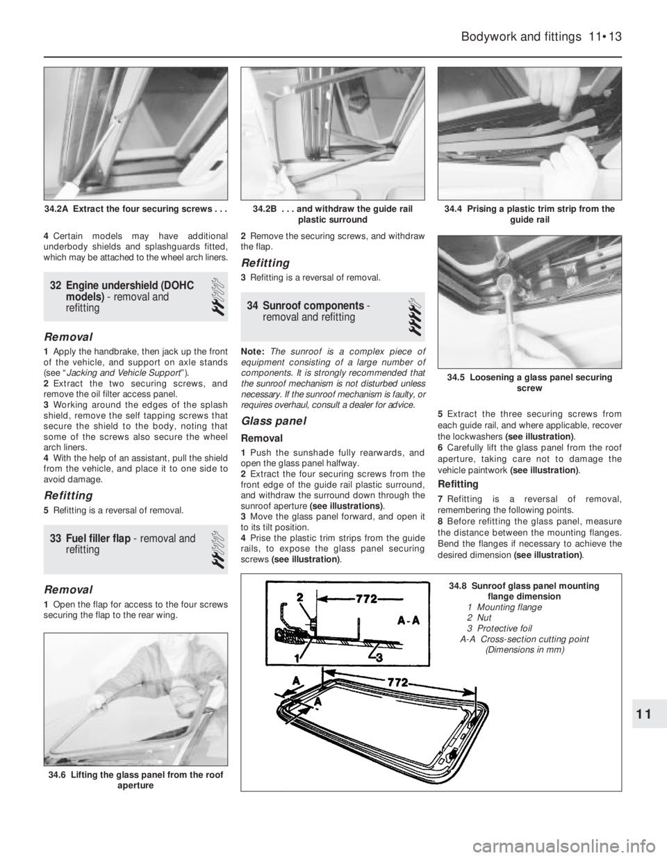
sunroof aperture (see illustrations).
3Move the glass panel forward, and open it
to its tilt position.
4Prise the plastic trim strips from the guide
rails, to expose the glass panel securing
screws (see illustration).5Extract the three securing screws from
each guide rail, and where applicable, recover
the lockwashers (see illustration).
6Carefully lift the glass panel from the roof
aperture, taking care not to damage the
vehicle paintwork (see illustration).
Refitting
7Refitting is a reversal of removal,
remembering the following points.
8Before refitting the glass panel, measure
the distance between the mounting flanges.
Bend the flanges if necessary to achieve the
desired dimension (see illustration).
Bodywork and fittings 11•13
34.4 Prising a plastic trim strip from the
guide rail
34.6 Lifting the glass panel from the roof
aperture
34.5 Loosening a glass panel securing
screw
34.2B . . . and withdraw the guide rail
plastic surround34.2A Extract the four securing screws . . .
11
34.8 Sunroof glass panel mounting
flange dimension
1 Mounting flange
2 Nut
3 Protective foil
A-A Cross-section cutting point
(Dimensions in mm)
Page 117 of 525
9Where applicable, ensure that the glass
panel securing screw lockwashers engage
with the locating pins on the guide rails.
10Before fully tightening the glass panel
securing screws, close the panel, and adjust
its position to give the dimensions shown (see
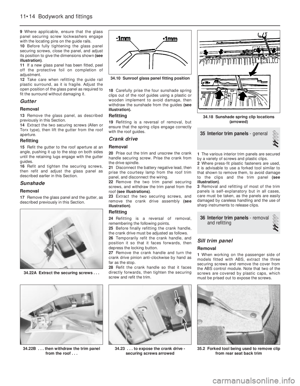
illustration).
11If a new glass panel has been fitted, peel
off the protective foil on completion of
adjustment.
12Take care when refitting the guide rail
plastic surround, as it is fragile. Adjust the
open position of the glass panel as required to
fit the surround without damaging it.
Gutter
Removal
13Remove the glass panel, as described
previously in this Section.
14Extract the two securing screws (Allen or
Torx type), then lift the gutter from the roof
aperture.
Refitting
15Refit the gutter to the roof aperture at an
angle, pushing it up to the stop on both sides
until the retaining lugs engage with the gutter
guides.
16Refit and tighten the securing screws,
then refit and adjust the glass panel as
described earlier in this Section.
Sunshade
Removal
17Remove the glass panel and the gutter, as
described previously in this Section. 18Carefully prise the four sunshade spring
clips out of the roof guides using a plastic or
wooden implement to avoid damage, then
withdraw the sunshade from the guides (see
illustration).
Refitting
19Refitting is a reversal of removal, but
ensure that the spring clips engage correctly
with the roof guides.
Crank drive
Removal
20Prise out the trim and unscrew the crank
handle securing screw. Prise the crank from
the drive spindle.
21Disconnect the battery negative lead, then
prise the courtesy lamp from the roof trim
panel, and disconnect the wiring.
22Remove the two trim panel securing
screws, and withdraw the trim panel from the
roof (see illustrations).
23Extract the two securing screws, and
remove the crank drive assembly (see
illustration).
Refitting
24Refitting is a reversal of removal,
remembering the following points.
25Before finally refitting the crank handle,
the crank drive must be adjusted as follows.
26Temporarily refit the crank handle, and
position it so that it faces forwards, then
depress the locking button.
27Remove the crank handle and turn the
crank drive pinion anti-clockwise by hand as
far as the stop.
28Refit the crank handle so that it faces
directly forwards, then tighten the securing
screw and refit the trim.
35Interior trim panels -general
2
1The various interior trim panels are secured
by a variety of screws and plastic clips.
2Where press-fit plastic fasteners are used,
it is advisable to use a forked tool similar to
that shown to remove them, to avoid damage
to the clips and the trim panel (see
illustration).
3Removal and refitting of most of the trim
panels is self-explanatory but in all cases,
care must be taken, as the panels are easily
damaged by careless handling and the use of
sharp instruments to release clips.
36Interior trim panels -removal
and refitting
2
Sill trim panel
Removal
1When working on the passenger side of
models fitted with ABS, extract the three
securing screws and remove the cover from
the ABS control module. Note that two of the
screws are covered by plastic caps, which
must be prised out to expose the screws.
11•14Bodywork and fittings
34.22A Extract the securing screws . . .
35.2 Forked tool being used to remove clip
from rear seat back trim34.23 . . . to expose the crank drive -
securing screws arrowed34.22B . . . then withdraw the trim panel
from the roof . . .
34.18 Sunshade spring clip locations
(arrowed)
34.10 Sunroof glass panel fitting position
Page 123 of 525
Refitting
10Refitting is a reversal of removal, but
where applicable, refit the sunroof crank drive,
as described in Section 34.
40Seats (without tensioners) -
removal and refitting
3
Front seats
Removal
1Remove the single securing screw from the
front edge of the outer seat rail trim, then
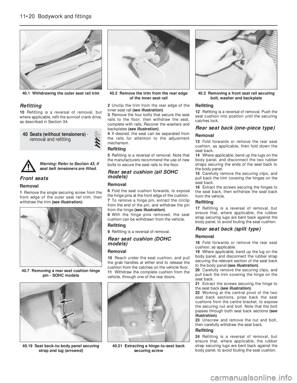
withdraw the trim (see illustration).2Unclip the trim from the rear edge of the
inner seat rail (see illustration).
3Remove the four bolts that secure the seat
rails to the floor, then withdraw the seat,
complete with rails. Recover the washers and
backplates (see illustration).
4If desired, the seat can be separated from
the rails for attention to the adjustment
mechanism.
Refitting
5Refitting is a reversal of removal. Note that
the manufacturers recommend the use of new
bolts to secure the seat rails to the floor.
Rear seat cushion (all SOHC
models)
Removal
6Fold the seat cushion forwards, to expose
the hinge pins at the front edge of the cushion.
7To remove a hinge pin, extract the circlip
from the end of the pin, and withdraw the pin
from the hinge (see illustration).
8With the hinge pins removed, the seat
cushion can be withdrawn from the vehicle.
Refitting
9Refitting is a reversal of removal.
Rear seat cushion (DOHC
models)
Removal
10Reach under the seat cushion, and pull
the grab handles at either end to release the
cushion from the catches on the vehicle floor.
11Withdraw the complete cushion from the
vehicle, through one of the rear doors.
Refitting
12Refitting is a reversal of removal. Push the
seat cushion into position until the securing
catches lock.
Rear seat back (one-piece type)
Removal
13Fold forwards or remove the rear seat
cushion, as applicable, then fold down the
seat back.
14Where applicable, bend up the lugs on the
body panel, and disconnect the two rubber
straps securing the ends of the seat back to
the body panel.
15Carefully remove the securing clips, and
pull back the trim covering the hinges on the
seat back.
16Extract the screws securing the hinges to
the seat back, then withdraw the seat back
from the vehicle.
Refitting
17Refitting is a reversal of removal, but
ensure that, where applicable, the rubber
strap securing lugs are bent back against the
body panel, to avoid fouling the seat cushion.
Rear seat back (split type)
Removal
18Fold forwards or remove the rear seat
cushion, as applicable.
19Where applicable, bend up the lug on the
body panel, and disconnect the rubber strap
securing the relevant section of the seat back
to the body panel (see illustration).
20Carefully remove the securing clips, and
pull back the trim covering the hinge on the
seat back.
21Extract the screws securing the hinge to
the seat back (see illustration).
22Working at the central pivot of the two
seat back sections, prise back the seat
cushions from the centre bracket, to expose
the securing nut and bolt. Note that the bolt
passes through both seat back sections (see
illustration).
23Unscrew and remove the nut and bolt,
then carefully withdraw the seat back.
Refitting
24Refitting is a reversal of removal, but
ensure that, where applicable, the rubber
strap securing lugs are bent back against the
body panel, to avoid fouling the seat cushion.
11•20Bodywork and fittings
40.1 Withdrawing the outer seat rail trim40.3 Removing a front seat rail securing
bolt, washer and backplate
40.7 Removing a rear seat cushion hinge
pin - SOHC models
40.21 Extracting a hinge-to-seat back
securing screw40.19 Seat back-to-body panel securing
strap and lug (arrowed)
40.2 Remove the trim from the rear edge
of the inner seat rail
Warning: Refer to Section 43, if
seat belt tensioners are fitted.
Page 125 of 525
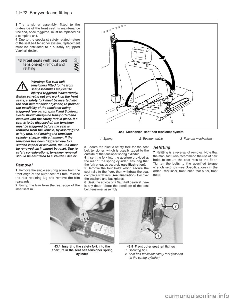
3The tensioner assembly, fitted to the
underside of the front seat, is maintenance
free and, once triggered, must be replaced as
a complete unit.
4Due to the specialist safety related nature
of the seat belt tensioner system, replacement
must be entrusted to a suitably equipped
Vauxhall dealer.
43Front seats (with seat belt
tensioners) -removal and
refitting
3
Removal
1Remove the single securing screw from the
front edge of the outer seat rail trim, release
the rear retaining lug and remove the trim
rearwards.
2Unclip the trim from the rear edge of the
inner seat rail.3Locate the plastic safety fork for the seat
belt tensioner, which is usually taped to the
outside of the tensioner spring cylinder.
4Insert the fork into the aperture provided at
the rear of the spring cylinder, ensuring that
the fork engages securely (see illustration).
5Remove the four bolts which secure the
seat rails to the floor, then withdraw the seat
complete with rails (see illustration). Recover
the washers and backplates.
6Seek the advice of a Vauxhall dealer if there
is any doubt about the condition of the seat
belt tensioner assembly.
Refitting
7Refitting is a reversal of removal. Note that
the manufacturers recommend the use of new
bolts to secure the seat rails to the floor.
Tighten the bolts to the specified torque
wrench settings (see Specifications) in the
order - rear inner, front inner, rear outer, front
outer.
11•22Bodywork and fittings
42.1 Mechanical seat belt tensioner system
1 Spring2 Bowden cable3 Fulcrum mechanism
43.5 Front outer seat rail fixings
1 Securing bolt
2 Seat belt tensioner safety fork (inserted
in the spring cylinder)43.4 Inserting the safety fork into the
aperture in the seat belt tensioner spring
cylinder
Warning: The seat belt
tensioners fitted to the front
seat assemblies may cause
injury if triggered inadvertently.
Before carrying out any work on the front
seats, a safety fork must be inserted into
the seat belt tensioner cylinder, to prevent
the possibility of the tensioner being
triggered (see paragraphs 7 and 8 below).
Seats should always be transported and
installed with the safety fork in place. If a
seat is to be disposed of, the tensioner
must be triggered before the seat is
removed from the vehicle, by inserting the
safety fork, and striking the tensioner
cylinder sharply with a hammer. If the
tensioner has been triggered due to a
sudden impact or accident, the unit must
be renewed, as it cannot be reset. Due to
safety considerations, tensioner renewal
should be entrusted to a Vauxhall dealer.
Page 128 of 525
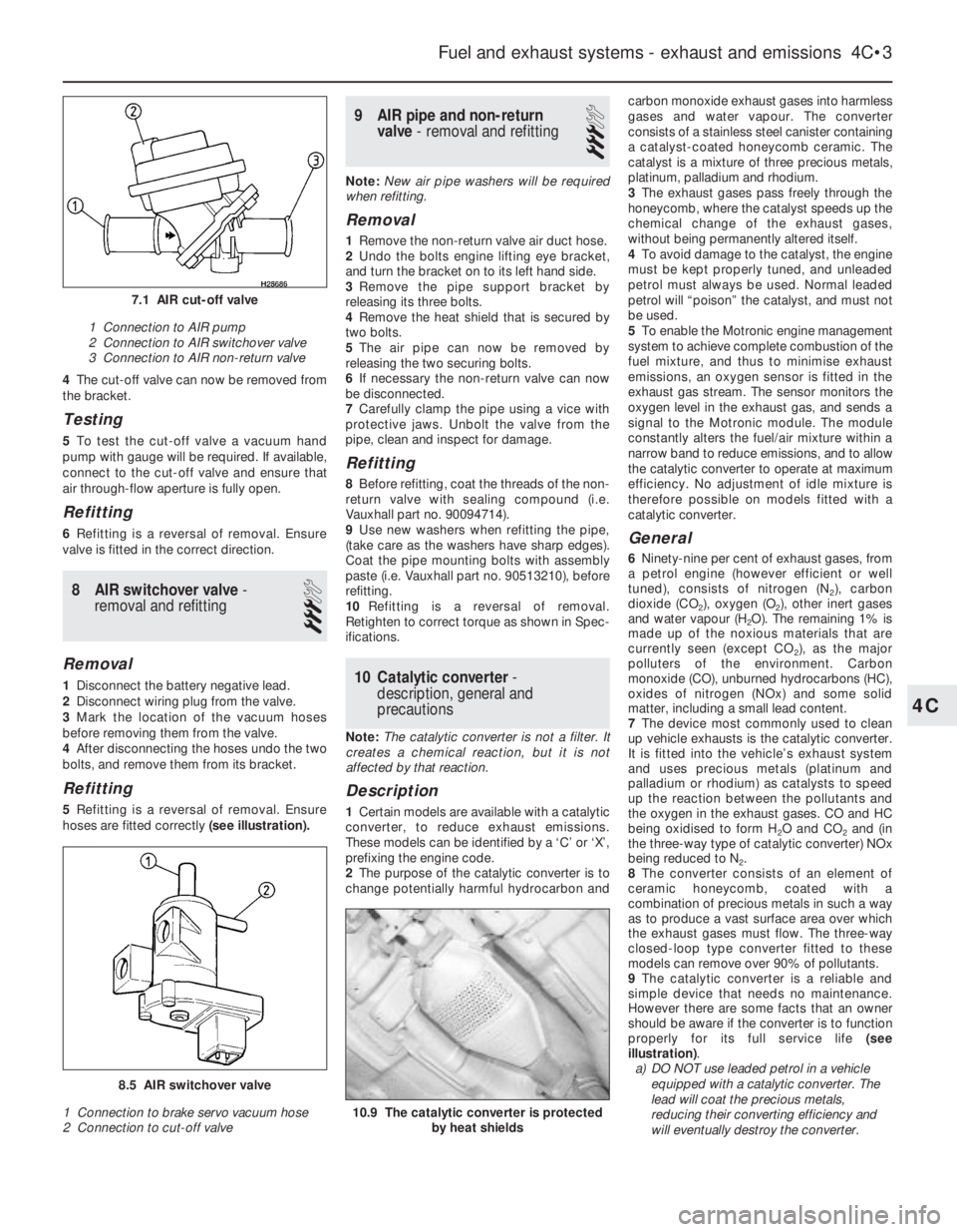
4The cut-off valve can now be removed from
the bracket.
Testing
5To test the cut-off valve a vacuum hand
pump with gauge will be required. If available,
connect to the cut-off valve and ensure that
air through-flow aperture is fully open.
Refitting
6Refitting is a reversal of removal. Ensure
valve is fitted in the correct direction.
8AIR switchover valve -
removal and refitting
3
Removal
1Disconnect the battery negative lead.
2Disconnect wiring plug from the valve.
3Mark the location of the vacuum hoses
before removing them from the valve.
4After disconnecting the hoses undo the two
bolts, and remove them from its bracket.
Refitting
5Refitting is a reversal of removal. Ensure
hoses are fitted correctly (see illustration).
9AIR pipe and non-return
valve - removal and refitting
3
Note:New air pipe washers will be required
when refitting.
Removal
1Remove the non-return valve air duct hose.
2Undo the bolts engine lifting eye bracket,
and turn the bracket on to its left hand side.
3Remove the pipe support bracket by
releasing its three bolts.
4Remove the heat shield that is secured by
two bolts.
5The air pipe can now be removed by
releasing the two securing bolts.
6If necessary the non-return valve can now
be disconnected.
7Carefully clamp the pipe using a vice with
protective jaws. Unbolt the valve from the
pipe, clean and inspect for damage.
Refitting
8Before refitting, coat the threads of the non-
return valve with sealing compound (i.e.
Vauxhall part no. 90094714).
9Use new washers when refitting the pipe,
(take care as the washers have sharp edges).
Coat the pipe mounting bolts with assembly
paste (i.e. Vauxhall part no. 90513210), before
refitting.
10Refitting is a reversal of removal.
Retighten to correct torque as shown in Spec-
ifications.
10Catalytic converter -
description, general and
precautions
Note: The catalytic converter is not a filter. It
creates a chemical reaction, but it is not
affected by that reaction.
Description
1Certain models are available with a catalytic
converter, to reduce exhaust emissions.
These models can be identified by a ‘C’ or ‘X’,
prefixing the engine code.
2The purpose of the catalytic converter is to
change potentially harmful hydrocarbon andcarbon monoxide exhaust gases into harmless
gases and water vapour. The converter
consists of a stainless steel canister containing
a catalyst-coated honeycomb ceramic. The
catalyst is a mixture of three precious metals,
platinum, palladium and rhodium.
3The exhaust gases pass freely through the
honeycomb, where the catalyst speeds up the
chemical change of the exhaust gases,
without being permanently altered itself.
4To avoid damage to the catalyst, the engine
must be kept properly tuned, and unleaded
petrol must always be used. Normal leaded
petrol will “poison” the catalyst, and must not
be used.
5To enable the Motronic engine management
system to achieve complete combustion of the
fuel mixture, and thus to minimise exhaust
emissions, an oxygen sensor is fitted in the
exhaust gas stream. The sensor monitors the
oxygen level in the exhaust gas, and sends a
signal to the Motronic module. The module
constantly alters the fuel/air mixture within a
narrow band to reduce emissions, and to allow
the catalytic converter to operate at maximum
efficiency. No adjustment of idle mixture is
therefore possible on models fitted with a
catalytic converter.
General
6Ninety-nine per cent of exhaust gases, from
a petrol engine (however efficient or well
tuned), consists of nitrogen (N
2), carbon
dioxide (CO
2), oxygen (O2), other inert gases
and water vapour (H
2O). The remaining 1% is
made up of the noxious materials that are
currently seen (except CO
2), as the major
polluters of the environment. Carbon
monoxide (CO), unburned hydrocarbons (HC),
oxides of nitrogen (NOx) and some solid
matter, including a small lead content.
7The device most commonly used to clean
up vehicle exhausts is the catalytic converter.
It is fitted into the vehicle’s exhaust system
and uses precious metals (platinum and
palladium or rhodium) as catalysts to speed
up the reaction between the pollutants and
the oxygen in the exhaust gases. CO and HC
being oxidised to form H
2O and CO2and (in
the three-way type of catalytic converter) NOx
being reduced to N
2.
8The converter consists of an element of
ceramic honeycomb, coated with a
combination of precious metals in such a way
as to produce a vast surface area over which
the exhaust gases must flow. The three-way
closed-loop type converter fitted to these
models can remove over 90% of pollutants.
9The catalytic converter is a reliable and
simple device that needs no maintenance.
However there are some facts that an owner
should be aware if the converter is to function
properly for its full service life (see
illustration).
a)DO NOT use leaded petrol in a vehicle
equipped with a catalytic converter. The
lead will coat the precious metals,
reducing their converting efficiency and
will eventually destroy the converter.
Fuel and exhaust systems - exhaust and emissions 4C•3
10.9 The catalytic converter is protected
by heat shields
8.5 AIR switchover valve
1 Connection to brake servo vacuum hose
2 Connection to cut-off valve
7.1 AIR cut-off valve
1 Connection to AIR pump
2 Connection to AIR switchover valve
3 Connection to AIR non-return valve
4C
Page 145 of 525

17Fit a new sealing ring to the end of the
cylinder bore.
18Where applicable, screw the pressure-
proportioning valves into the base of the
cylinder.
19Refit the master cylinder, as described in
Section 15.
ATE type master cylinder
20Clamp the master cylinder in a soft-jawed
vice.
21Where applicable, unscrew the pressure-
proportioning valves from the base of the
cylinder.
22Carefully prise out the sealing ring from
the end of the cylinder bore.
23Depress the primary piston slightly using
a piece of wood or plastic, then extract the
circlip from the end of the cylinder bore.
24Withdraw the primary piston assembly,
noting the location of the stop washers.
25Depress the secondary piston, again
using a piece of wood or plastic, and
withdraw the stop screw from the cylinder
body (see illustration).
26Withdraw the secondary piston assembly
from the cylinder, if necessary tapping the
cylinder on a wooden block to free the piston
from the bore.
27Clean all the components, in clean brake
fluid or methylated spirit only, and examine
them for wear and damage. In particular,
check the surfaces of the pistons and cylinder
bores for scoring and corrosion. If the bore
shows signs of wear, renew the complete
master cylinder assembly (see illustration).28If the cylinder bore is in good condition,
obtain a repair kit, which will contain all the
necessary renewable items. A Vauxhall dealer
will supply a complete kit of parts, which
should be fitted as follows.
29Lubricate the cylinder bore with clean
brake fluid or brake grease, then clamp the
cylinder in a soft-jawed vice, with the bore
horizontal.
30Fit a new sealing ring to the stop screw,
then screw it into the cylinder body a little
way, but not so far that it protrudes into the
bore.
31Remove the plugs from the ends of the
assembly tube, then remove all the
components from the short part of the tube,
and push the short part into the long part until
they are flush.
32Insert the assembly tube into the cylinder
bore as far as the collar on the short sleeve.
Then use a piece of wood or plastic to push
the secondary piston assembly into the bore
until it contacts the end of the cylinder.
33Lightly tighten the stop screw, then
withdraw the piece of wood or plastic and the
assembly tube, and fully tighten the stop
screw.
34Reposition the master cylinder in the vice,
with the bore facing upwards.
35Smear the primary piston skirt and the
seal grooves with the special grease provided
in the repair kit. Fit the stop washer to the
piston.
36Adjust the assembly tube so that the end
of the long part is flush with the inner shoulder
of the short part.37Fit the front seal to the primary piston,
with the open end of the seal facing the front
of the master cylinder.
38Place the assembly tube over the cylinder
to compress the seal, insert the piston and
tube part way into the bore, and withdraw the
tube.
39Place the intermediate ring on the primary
piston, then fit the remaining seal using the
assembly tube as described previously.
40Place the stop washer as the primary
piston, then depress the piston slightly using
a piece of wood or plastic, and fit a new circlip
to the end of the cylinder bore. Ensure that the
circlip is correctly seated, and that the piston
is free to move.
41Fit a new sealing ring to the end of the
cylinder bore.
9•14Braking system
16.25 Depressing the secondary piston
while extracting the stop screw - ATE type
master cylinder
16.27 Exploded view of ATE type master
cylinder
1 Filler cap (standard)
2 Strainer
3 Filler cap (with fluid level sensor)
4 Guide sleeve for float
5 Fluid reservoir
6 Cylinder body
7 Sealing ring
8 Fluid reservoir seals
9 Stop screw
10 Repair kit assembly tube
11 Pressure-proportioning valves
16.10 Exploded view of GMF type master
cylinder
1 Filler cap (standard)
2 Filler cap (with fluid level sensor)
3 Fluid reservoir
4 Fluid reservoir retaining clips
5 Fluid reservoir seals
6 Cylinder body
7 Secondary piston and springs
8 Primary piston
9 Circlip
10 Sealing ring
11 Pressure-proportioning valves
Page 152 of 525
19On DOHC models, use a new self-locking
nut to secure the equaliser yoke to the
handbrake lever operating rod, and screw the
nut onto the rod to the position noted before
removal.
20On SOHC models, tighten the cable
adjuster to expose the length of thread noted
before removal.
21Before lowering the vehicle to the ground,
adjust the handbrake, (Section 26).
29Brake pedal - removal and
refitting
3
Removal
1Disconnect the battery negative lead.
2Remove the lower trim panel from the
driver’s footwell.3Disconnect the wiring plug from the brake
lamp switch, then twist the switch anti-
clockwise and remove it from its bracket.
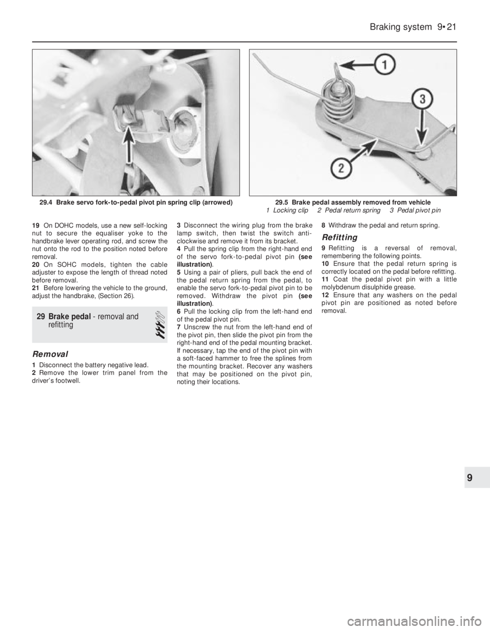
4Pull the spring clip from the right-hand end
of the servo fork-to-pedal pivot pin (see
illustration).
5Using a pair of pliers, pull back the end of
the pedal return spring from the pedal, to
enable the servo fork-to-pedal pivot pin to be
removed. Withdraw the pivot pin (see
illustration).
6Pull the locking clip from the left-hand end
of the pedal pivot pin.
7Unscrew the nut from the left-hand end of
the pivot pin, then slide the pivot pin from the
right-hand end of the pedal mounting bracket.
If necessary, tap the end of the pivot pin with
a soft-faced hammer to free the splines from
the mounting bracket. Recover any washers
that may be positioned on the pivot pin,
noting their locations.8Withdraw the pedal and return spring.
Refitting
9Refitting is a reversal of removal,
remembering the following points.
10Ensure that the pedal return spring is
correctly located on the pedal before refitting.
11Coat the pedal pivot pin with a little
molybdenum disulphide grease.
12Ensure that any washers on the pedal
pivot pin are positioned as noted before
removal.
Braking system 9•21
29.5 Brake pedal assembly removed from vehicle
1 Locking clip 2 Pedal return spring 3 Pedal pivot pin29.4 Brake servo fork-to-pedal pivot pin spring clip (arrowed)
9