1988 OPEL CALIBRA washer
[x] Cancel search: washerPage 194 of 525
pitting. If evident, the cylinder head and all
bearing caps must be renewed as a matched
set, as there is no provision for refacing if the
bearing caps cannot be renewed individually.
8The camshaft(s) should show no marks or
scoring on the journal or cam lobe surfaces. if
evident, renew the camshaft(s).
9It is advisable to renew the camshaft front
oil seal(s) as a matter of course. Prise the old
seal(s) from the front of the camshaft(s) and
discard them.
Refitting
10Begin refitting by liberally coating the
contact faces of the hydraulic valve lifters and
the camshaft(s) with molybdenum disulphide
paste.
11Coat the mating faces of the front and
rear bearing caps with sealing compound and
refit the bearing caps in their original positions
as noted during removal.
12Tighten the camshaft bearing cap nuts to
the specified torque in half-turn stages, as
when loosening the nuts. Note that when
refitting the exhaust camshaft, the two smaller
rear bearing cap securing nuts should be
tightened after all the main camshaft bearing
cap nuts have been tightened. Note also that
the two smaller nuts should be tightened to a
lower torque wrench setting than the main
nuts.
13Turn the camshaft until the locating peg
for the camshaft sprocket is uppermost, then
lubricate the lips of a rear camshaft front oil
seal with a little grease, and fit the oil seal,
using a tube or socket of similar diameter with
a washer and the camshaft sprocket bolt.
Screw the camshaft sprocket bolt into the end
of the camshaft to draw the oil seal into
position on its shoulder.
14Repeat the procedure for the remaining
camshaft.
15Refit the distributor with reference to
Chapter 5. Fit a new timing belt and the
camshaft sprockets, then adjust the timing
belt as described in Section 4 or 5, as
applicable.
8Cylinder head -removal and
refitting (engine in vehicle)
4
Note: The engine must be cold when the
cylinder head is removed. Do not remove the
cylinder head from a hot engine. New cylinder
head bolts, a new cylinder head gasket and a
new timing belt must be used on refitting.
The torque settings (as shown in Chapter 2A)
are only applicable to latest specification head
bolts, available from Vauxhall. Earlier type or
alternative make, head bolts may require
different torques. Consult your supplier
Removal
1Disconnect the battery negative lead.
2Drain the cooling system, as described in
Chapter 3.3Remove the front section of the exhaust
system, as described in Chapter 4C.
4The cylinder head can be removed
complete with the inlet manifold, or the inlet
manifold can be detached from the cylinder
head before removal, with reference to
Chapter 4B. If no work is to be carried out on
the inlet manifold, it can be unbolted from the
cylinder head and supported to one side out
of the way, thus avoiding the need to
disconnect the relevant hoses, pipes and
wiring.
5If the cylinder head is to be removed
complete with the inlet manifold, disconnect
all relevant hoses, pipes and wiring from the
inlet manifold and associated components,
referring to Chapter 4B, and unbolt the
manifold support bracket from the manifold.
Loosen the alternator mountings with
reference to Chapter 5, then unbolt the upper
alternator mounting from the inlet manifold.
6If the inlet manifold is to be left in the engine
compartment, continue as follows, otherwise
go on to paragraph 17.
7Disconnect the wiring plug from the airflow
meter, and the breather hose from the air box
on the throttle body. Disconnect the air
cleaner trunking and remove the airflow
meter/air box assembly from the throttle
body. Refer to Chapter 4B if necessary.
8Disconnect the end of the throttle cable
from the throttle valve lever, then unbolt the
throttle cable support bracket and remove it
from the inlet manifold.
9Unscrew the two earth lead securing nuts
from the fuel rail (one at each end of the rail)
and disconnect the three earth leads.
10Disconnect the wiring plug from the
throttle position switch.
11Pull up on the wiring harness housing, and
disconnect the wiring plugs from the fuel
injectors by compressing the retaining clips.
Move the wiring harness housing to one side.
12Disconnect the two breather hoses from
the rear of the camshaft cover.
13Loosen the alternator mountings, with
reference to Chapter 5, then unbolt the upper
alternator mounting from the inlet manifold.
14Unbolt the manifold support bracket from
the manifold.15Make a final check to ensure that all
necessary hoses, pipes and wires have been
disconnected, then unscrew the securing nuts
and lift the inlet manifold from the cylinder
head. Ensure that the manifold is properly
supported, taking care not to strain any of the
hoses, pipes and wires, etc., which are still
connected.
16Recover the manifold gasket from the
cylinder head.
17Remove the timing belt, camshaft
sprockets, and timing belt tensioner and idler
pulleys, as described in Section 4.
18Unscrew the upper and middle studs for
the timing belt outer cover screws. Note that
the upper stud simply unscrews from the
cylinder head, but the middle stud is secured
by a bolt.
19Unscrew the two upper rear timing belt
cover securing bolts from the cylinder head.
20Remove the distributor cap and HT leads
with reference to Chapter 5.
21Disconnect the distributor wiring plug.
22Disconnect the coolant hose from the
left-hand end of the cylinder head.
23Unscrew the bolt securing the crankcase
breather tube bracket to the end of the
cylinder head.
24Disconnect the radiator top hose from the
thermostat housing, and disconnect the
wiring plugs from the temperature gauge
sender and the coolant temperature sensor
(both situated in the thermostat housing).
25Make a final check to ensure that all
relevant hoses, pipes and wires have been
disconnected.
26On X20 XEV models, remove the
camshaft, as described in Section 7.
27Using a Torx socket, and working in the
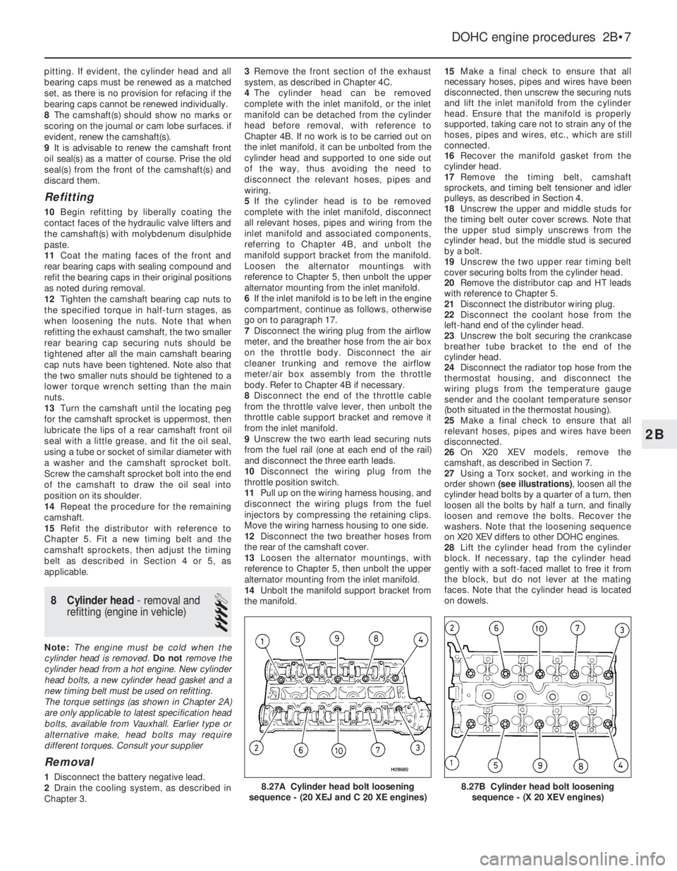
order shown (see illustrations), loosen all the
cylinder head bolts by a quarter of a turn, then
loosen all the bolts by half a turn, and finally
loosen and remove the bolts. Recover the
washers. Note that the loosening sequence
on X20 XEV differs to other DOHC engines.
28Lift the cylinder head from the cylinder
block. If necessary, tap the cylinder head
gently with a soft-faced mallet to free it from
the block, but do not lever at the mating
faces. Note that the cylinder head is located
on dowels.
DOHC engine procedures 2B•7
8.27B Cylinder head bolt loosening
sequence - (X 20 XEV engines)8.27A Cylinder head bolt loosening
sequence - (20 XEJ and C 20 XE engines)
2B
Page 195 of 525
29Recover the cylinder head gasket and
discard it.
30Clean the cylinder head and block mating
faces by careful scraping. Take care not to
damage the cylinder head, which is made of
light alloy and is easily scored. Cover the
coolant passages and other openings with
masking tape or rag, to prevent dirt and
carbon falling in. Mop out all the oil from the
bolt holes; if oil is left in the holes, hydraulic
pressure could crack the block when the bolts
are refitted.
31If desired, the cylinder head can be
dismantled and inspected as described in
Section 10.
Refitting
32Begin refitting by locating a new gasket
on the block so that the word “OBEN” or
“TOP” is uppermost at the timing belt end of
the engine.
33With the mating faces scrupulously clean,
locate the cylinder head on the block so that
the positioning dowels engage in their holes.
34Temporarily refit the crankshaft pulley and
the camshaft sprockets, and ensure that the
timing marks are still positioned as they were
before the timing belt was removed (see
Section 4).35Fit the new cylinder head bolts, ensuring
that the washers are in place under their
heads, and screw the bolts in by hand as far
as possible.
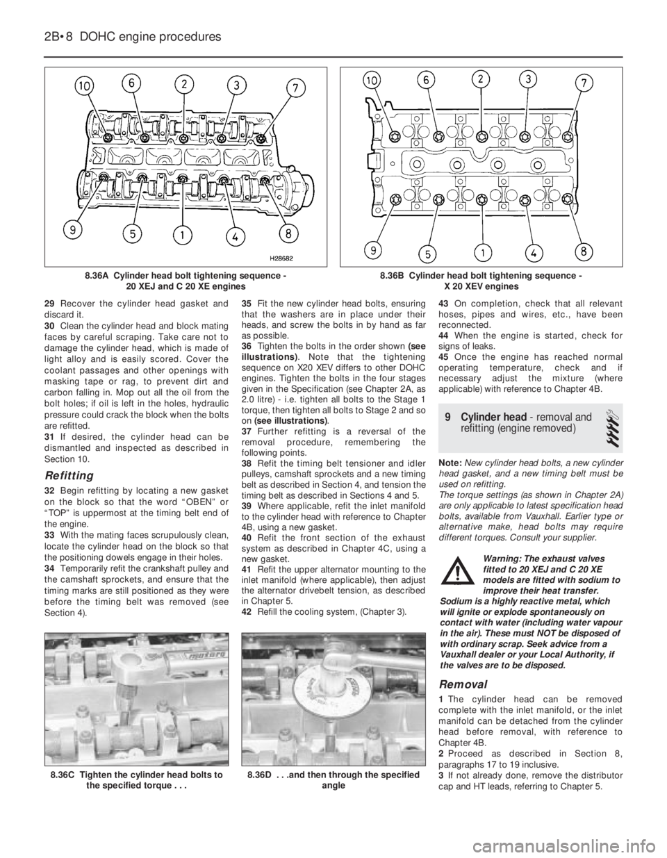
36Tighten the bolts in the order shown (see
illustrations). Note that the tightening
sequence on X20 XEV differs to other DOHC
engines. Tighten the bolts in the four stages
given in the Specification (see Chapter 2A, as
2.0 litre) - i.e. tighten all bolts to the Stage 1
torque, then tighten all bolts to Stage 2 and so
on (see illustrations).
37Further refitting is a reversal of the
removal procedure, remembering the
following points.
38Refit the timing belt tensioner and idler
pulleys, camshaft sprockets and a new timing
belt as described in Section 4, and tension the
timing belt as described in Sections 4 and 5.
39Where applicable, refit the inlet manifold
to the cylinder head with reference to Chapter
4B, using a new gasket.
40Refit the front section of the exhaust
system as described in Chapter 4C, using a
new gasket.
41Refit the upper alternator mounting to the
inlet manifold (where applicable), then adjust
the alternator drivebelt tension, as described
in Chapter 5.
42Refill the cooling system, (Chapter 3).43On completion, check that all relevant
hoses, pipes and wires, etc., have been
reconnected.
44When the engine is started, check for
signs of leaks.
45Once the engine has reached normal
operating temperature, check and if
necessary adjust the mixture (where
applicable) with reference to Chapter 4B.
9Cylinder head -removal and
refitting (engine removed)
4
Note: New cylinder head bolts, a new cylinder
head gasket, and a new timing belt must be
used on refitting.
The torque settings (as shown in Chapter 2A)
are only applicable to latest specification head
bolts, available from Vauxhall. Earlier type or
alternative make, head bolts may require
different torques. Consult your supplier.
Removal
1The cylinder head can be removed
complete with the inlet manifold, or the inlet
manifold can be detached from the cylinder
head before removal, with reference to
Chapter 4B.
2Proceed as described in Section 8,
paragraphs 17 to 19 inclusive.
3If not already done, remove the distributor
cap and HT leads, referring to Chapter 5.
2B•8DOHC engine procedures
8.36A Cylinder head bolt tightening sequence -
20 XEJ and C 20 XE engines
8.36C Tighten the cylinder head bolts to
the specified torque . . .8.36D . . .and then through the specified
angle
8.36B Cylinder head bolt tightening sequence -
X 20 XEV engines
Warning: The exhaust valves
fitted to 20 XEJ and C 20 XE
models are fitted with sodium to
improve their heat transfer.
Sodium is a highly reactive metal, which
will ignite or explode spontaneously on
contact with water (including water vapour
in the air). These must NOT be disposed of
with ordinary scrap. Seek advice from a
Vauxhall dealer or your Local Authority, if
the valves are to be disposed.
Page 209 of 525
9Engine and transmission
mountings - renewal
3
Note: New left and right-hand
engine/transmission mounting-to-body bolts
must be used on refitting
1The engine/transmission assembly is
suspended in the engine compartment on
three mountings, two of which are attached to
the transmission, and one to the engine.
Right-hand mounting
2If not already done, apply the handbrake,
then raise the front of the vehicle, and support
securely on axle stands (see “Jacking and
Vehicle Support”)..
3Attach lifting tackle and a hoist to the
engine lifting brackets on the cylinder head,
and support the weight of the engine.
4Working under the vehicle, unbolt the
engine mounting bracket from the cylinder
block, and unbolt the mounting block from the
body, then withdraw the bracket/mounting
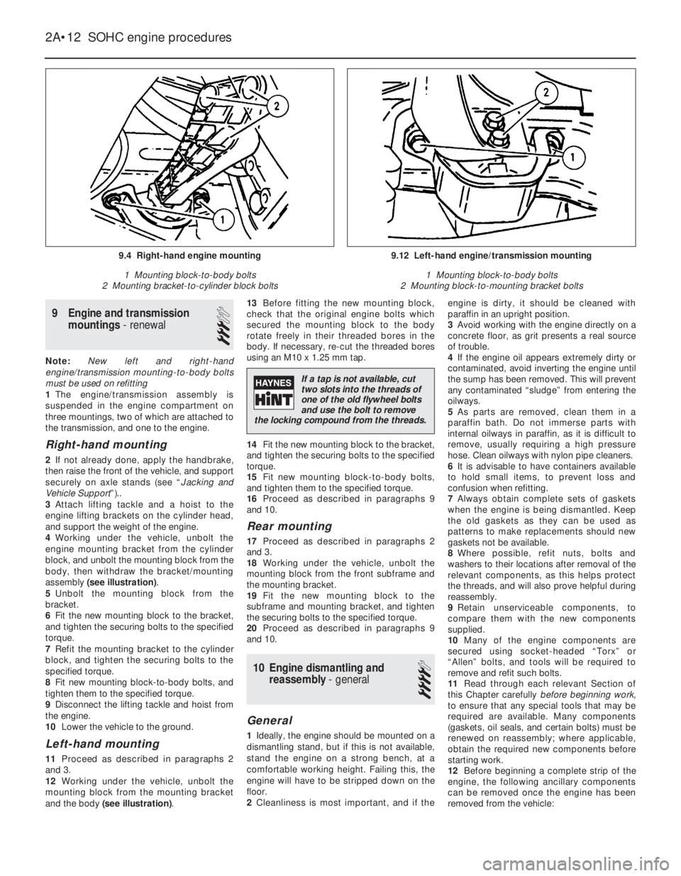
assembly (see illustration).
5Unbolt the mounting block from the
bracket.
6Fit the new mounting block to the bracket,
and tighten the securing bolts to the specified
torque.
7Refit the mounting bracket to the cylinder
block, and tighten the securing bolts to the
specified torque.
8Fit new mounting block-to-body bolts, and
tighten them to the specified torque.
9Disconnect the lifting tackle and hoist from
the engine.
10Lower the vehicle to the ground.
Left-hand mounting
11Proceed as described in paragraphs 2
and 3.
12Working under the vehicle, unbolt the
mounting block from the mounting bracket
and the body (see illustration).13Before fitting the new mounting block,
check that the original engine bolts which
secured the mounting block to the body
rotate freely in their threaded bores in the
body. If necessary, re-cut the threaded bores
using an M10 x 1.25 mm tap.
14Fit the new mounting block to the bracket,
and tighten the securing bolts to the specified
torque.
15Fit new mounting block-to-body bolts,
and tighten them to the specified torque.
16Proceed as described in paragraphs 9
and 10.
Rear mounting
17Proceed as described in paragraphs 2
and 3.
18Working under the vehicle, unbolt the
mounting block from the front subframe and
the mounting bracket.
19Fit the new mounting block to the
subframe and mounting bracket, and tighten
the securing bolts to the specified torque.
20Proceed as described in paragraphs 9
and 10.
10Engine dismantling and
reassembly - general
4
General
1Ideally, the engine should be mounted on a
dismantling stand, but if this is not available,
stand the engine on a strong bench, at a
comfortable working height. Failing this, the
engine will have to be stripped down on the
floor.
2Cleanliness is most important, and if theengine is dirty, it should be cleaned with
paraffin in an upright position.
3Avoid working with the engine directly on a
concrete floor, as grit presents a real source
of trouble.
4If the engine oil appears extremely dirty or
contaminated, avoid inverting the engine until
the sump has been removed. This will prevent
any contaminated “sludge” from entering the
oilways.
5As parts are removed, clean them in a
paraffin bath. Do not immerse parts with
internal oilways in paraffin, as it is difficult to
remove, usually requiring a high pressure
hose. Clean oilways with nylon pipe cleaners.
6It is advisable to have containers available
to hold small items, to prevent loss and
confusion when refitting.
7Always obtain complete sets of gaskets
when the engine is being dismantled. Keep
the old gaskets as they can be used as
patterns to make replacements should new
gaskets not be available.
8Where possible, refit nuts, bolts and
washers to their locations after removal of the
relevant components, as this helps protect
the threads, and will also prove helpful during
reassembly.
9Retain unserviceable components, to
compare them with the new components
supplied.
10Many of the engine components are
secured using socket-headed “Torx” or
“Allen” bolts, and tools will be required to
remove and refit such bolts.
11Read through each relevant Section of
this Chapter carefullybeforebeginning work,
to ensure that any special tools that may be
required are available. Many components
(gaskets, oil seals, and certain bolts) must be
renewed on reassembly; where applicable,
obtain the required new components before
starting work.
12Before beginning a complete strip of the
engine, the following ancillary components
can be removed once the engine has been
removed from the vehicle:
2A•12SOHC engine procedures
9.4 Right-hand engine mounting
1 Mounting block-to-body bolts
2 Mounting bracket-to-cylinder block bolts9.12 Left-hand engine/transmission mounting
1 Mounting block-to-body bolts
2 Mounting block-to-mounting bracket bolts
If a tap is not available, cut
two slots into the threads of
one of the old flywheel bolts
and use the bolt to remove
the locking compound from the threads.
Page 210 of 525
a)Inlet and exhaust manifolds (where
applicable)
b)Starter motor
c)Rear coolant gallery and hoses
d)Oil pressure switch
e)Oil temperature switch (where applicable)
f)Oil level sensor (where applicable)
g)Knock sensor (where applicable)
h)TDC sensor (where applicable)
i)Distributor components
j)Fuel pump (where applicable)
k)Thermostat/housing (N 16 NZ2, 1.8 and
2.0 litre models)
l)Power steering pump and mounting
bracket (where applicable)
m)Alternator mounting bracket
n)Engine lifting brackets
o)Dipstick/crankcase breather tube
p)Inlet manifold mounting bracket (where
applicable)
13To ensure maximum life, with minimum
trouble, from a rebuilt engine, not only must
everything be correctly assembled, but it must
also be spotlessly clean. All oilways and
coolant passages must be clear, and all
washers must be fitted in their original
positions. Oil all bearings and other moving
surfaces thoroughly with clean engine oil
during assembly.
14Before assembly begins, renew any bolts
or studs with damaged threads.
15Obtain a torque wrench, an angle-torque
gauge, sockets and bits, an oil can, clean
lint-free rag, and a set of engine gaskets and
oil seals, together with a new oil filter.16If they have been removed, new cylinder
head bolts, flywheel bolts, big-end bearing
cap bolts and main bearing cap bolts will also
be required.
17On completion of reassembly, refit the
applicable ancillary components listed in
paragraph 12.
18Follow procedure shown in Section 37.
11Timing belt and sprockets
(without automatic tensioner) -
removal, refitting and adjustment
3
Note: A two-legged puller may be required to
remove the crankshaft sprocket on N 16 NZ2,
1.8 and 2.0 litre models.Some of the later 1.4
and 1.6 litre engines, identifiable by the
squared-off top surfaces of the timing belt
covers, are fitted with spring-loaded auto-matic timing belt tensioners to ensure correct
belt tensioning on assembly.
Removal
1Disconnect the battery negative lead.
2On models with power steering, remove the
pump drivebelt, see Chapters 1 and 10.
3Remove the alternator drivebelt, as
described in Chapter 5.
4On C 16 NZ2, 1.8 and 2.0 litre models,
disconnect the wiring from the temperature
gauge sender.
5Release the securing clips (or hexagon-
headed screws, if fitted), and remove the main
outer timing belt cover, then unclip the smaller
outer timing belt cover from the coolant pump.
Where applicable, three screws retain the lower
(small) outer cover to the rear cover, the fourth
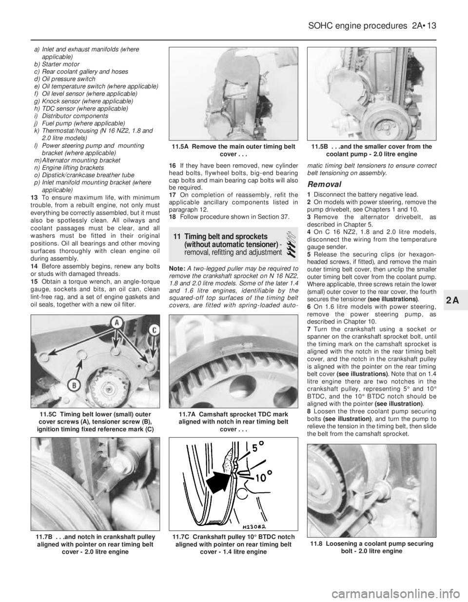
secures the tensioner (see illustrations).
6On 1.6 litre models with power steering,
remove the power steering pump, as
described in Chapter 10.
7Turn the crankshaft using a socket or
spanner on the crankshaft sprocket bolt, until
the timing mark on the camshaft sprocket is
aligned with the notch in the rear timing belt
cover, and the notch in the crankshaft pulley
is aligned with the pointer on the rear timing
belt cover (see illustrations). Note that on 1.4
litre engine there are two notches in the
crankshaft pulley, representing 5°and 10°
BTDC, and the 10°BTDC notch should be
aligned with the pointer (see illustration).
8Loosen the three coolant pump securing
bolts (see illustration), and turn the pump to
relieve the tension in the timing belt, then slide
the belt from the camshaft sprocket.
SOHC engine procedures 2A•13
11.5C Timing belt lower (small) outer
cover screws (A), tensioner screw (B),
ignition timing fixed reference mark (C)
11.8 Loosening a coolant pump securing
bolt - 2.0 litre engine11.7C Crankshaft pulley 10°BTDC notch
aligned with pointer on rear timing belt
cover - 1.4 litre engine11.7B . . .and notch in crankshaft pulley
aligned with pointer on rear timing belt
cover - 2.0 litre engine
11.7A Camshaft sprocket TDC mark
aligned with notch in rear timing belt
cover . . .
11.5B . . .and the smaller cover from the
coolant pump - 2.0 litre engine11.5A Remove the main outer timing belt
cover . . .
2A
Page 211 of 525

9The crankshaft pulley must now be
removed. On 1.4 and 1.6 litre engines (except
C 16 NZ2), the pulley is secured by a single
bolt, which also secures the crankshaft
sprocket. On C 16 NZ2, 1.8 and 2.0 litre
engines, the pulley is secured by four bolts,
which must be unscrewed using an Allen key
or hexagon bit. On manual transmission
models, if the engine is in the vehicle, the
crankshaft can be prevented from turning by
having an assistant engage first gear and
depress the brake pedal. Alternatively, the
flywheel ring gear teeth can be jammed using
a large screwdriver or similar tool.
10With the crankshaft pulley removed, the
timing belt can be withdrawn.
11If desired, the sprockets and the rear
timing belt cover can be removed as follows,
otherwise go on to paragraph 23.
12To remove the camshaft sprocket, firstdisconnect the breather hose(s) from the
camshaft cover, then unscrew the securing
bolts noting the locations of the HT lead
brackets and any other wiring brackets, and
remove the camshaft cover.
13Recover the gasket. Prevent the camshaft
from turning by holding it with a spanner on
the flats provided between No’s 3 and 4
camshaft lobes, and unscrew the camshaft
sprocket bolt.
14Withdraw the sprocket from the end of the
camshaft.
15To remove the crankshaft sprocket on 1.4
and 1.6 litre engines (except C 16 NZ2), if
necessary, remove the lower securing bolts
from the main rear timing belt cover and use
two large screwdrivers behind the cover to
lever off the sprocket. Remove the Woodruff
key if it is loose.
16To remove the crankshaft sprocket on C
16 NZ2, 1.8 and 2.0 litre engines, it will benecessary to prevent the crankshaft from
turning, as described in paragraph 9. Take
care when unscrewing the sprocket bolt, as it
is very tight. If necessary, use a two-legged
puller to remove the sprocket. Recover the
Woodruff key and the thrustwasher from the
end of the crankshaft.
17To remove the main rear timing belt cover
on C 16 NZ2, 1.8 and 2.0 litre models
disconnect the TDC sensor wiring plug and
unclip the wiring from the belt cover. Then
unscrew the two upper securing bolts and the
lower securing bolt(s) (one in the case of C 16
NZ2, 1.8 and 2.0 litre engines, two on other
SOHC engines). Withdraw the cover,
manipulating it from the smaller rear belt
cover on the coolant pump (see illustrations).
18If desired, the smaller rear belt cover can
be removed from the coolant pump, after
unscrewing the securing bolt (see
illustration), by rotating it to disengage it from
the retaining flange on the pump.
Refitting
19Refit the rear timing belt cover(s) using a
reversal of the removal procedure, and
ensuring that the main cover engages correctly
with the smaller cover on the coolant pump.
20On C 16 NZ2, 1.8 and 2.0 litre engines,
refit the thrustwasher and the Woodruff key to
the end of the crankshaft. Then refit the
crankshaft sprocket, and tighten the securing
bolt to the specified torque in the two stages
given in the Specifications. Ensure that the
washer is in place under the bolt head, and
prevent the crankshaft from turning as during
removal (see illustrations).
2A•14SOHC engine procedures
11.17A Loosening the main rear timing
belt cover lower securing bolt -
2.0 litre engine11.18 Unscrewing the coolant pump rear
belt cover securing bolt - 2.0 litre engine
11.20E Tighten the bolt to the specified
torque . . .11.20D . . .and the washer and bolt11.20C . . .the crankshaft sprocket . . .
11.20B . . . the Woodruff key . . .11.20A Refit the thrustwasher . . .
11.17B Main rear timing belt cover lower
securing bolts (arrowed) - 1.6 SV engine
Page 217 of 525
supported to one side out of the way, thus
avoiding the need to disconnect the relevant
hoses, pipes and wiring.
5If the cylinder head is to be removed
complete with the manifolds, disconnect all
relevant hoses, pipes and wiring from the inlet
manifold and associated components,
referring to Chapter 4A or 4B. On carburettor
models, disconnect the hot air hose from the
shroud on the exhaust manifold. Loosen the
alternator mountings, with reference to
Chapter 5, then unbolt the upper alternator
mounting from the inlet manifold.
6If the inlet manifold is to be left in the engine
compartment, continue as follows, otherwise
go on to paragraph 15.
7Disconnect the air cleaner trunking from the
air box on the carburettor or throttle body, or
directly from the throttle body (as applicable),
and disconnect the camshaft cover breather
hose that runs to the carburettor or throttle
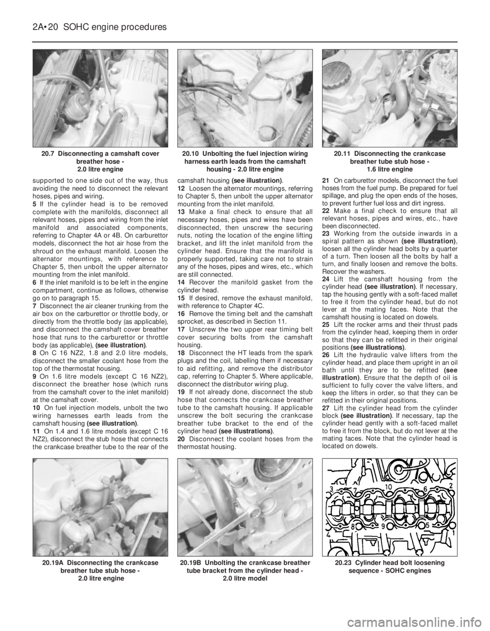
body (as applicable), (see illustration).
8On C 16 NZ2, 1.8 and 2.0 litre models,
disconnect the smaller coolant hose from the
top of the thermostat housing.
9On 1.6 litre models (except C 16 NZ2),
disconnect the breather hose (which runs
from the camshaft cover to the inlet manifold)
at the camshaft cover.
10On fuel injection models, unbolt the two
wiring harnesses earth leads from the
camshaft housing (see illustration).
11On 1.4 and 1.6 litre models (except C 16
NZ2), disconnect the stub hose that connects
the crankcase breather tube to the rear of thecamshaft housing (see illustration).
12Loosen the alternator mountings, referring
to Chapter 5, then unbolt the upper alternator
mounting from the inlet manifold.
13Make a final check to ensure that all
necessary hoses, pipes and wires have been
disconnected, then unscrew the securing
nuts, noting the location of the engine lifting
bracket, and lift the inlet manifold from the
cylinder head. Ensure that the manifold is
properly supported, taking care not to strain
any of the hoses, pipes and wires, etc., which
are still connected.
14Recover the manifold gasket from the
cylinder head.
15If desired, remove the exhaust manifold,
with reference to Chapter 4C.
16Remove the timing belt and the camshaft
sprocket, as described in Section 11.
17Unscrew the two upper rear timing belt
cover securing bolts from the camshaft
housing.
18Disconnect the HT leads from the spark
plugs and the coil, labelling them if necessary
to aid refitting, and remove the distributor
cap, referring to Chapter 5. Where applicable,
disconnect the distributor wiring plug.
19If not already done, disconnect the stub
hose that connects the crankcase breather
tube to the camshaft housing. If applicable
unscrew the bolt securing the crankcase
breather tube bracket to the end of the
cylinder head (see illustrations).
20Disconnect the coolant hoses from the
thermostat housing.21On carburettor models, disconnect the fuel
hoses from the fuel pump. Be prepared for fuel
spillage, and plug the open ends of the hoses,
to prevent further fuel loss and dirt ingress.
22Make a final check to ensure that all
relevant hoses, pipes and wires, etc., have
been disconnected.
23Working from the outside inwards in a
spiral pattern as shown (see illustration),
loosen all the cylinder head bolts by a quarter
of a turn. Then loosen all the bolts by half a
turn, and finally loosen and remove the bolts.
Recover the washers.
24Lift the camshaft housing from the
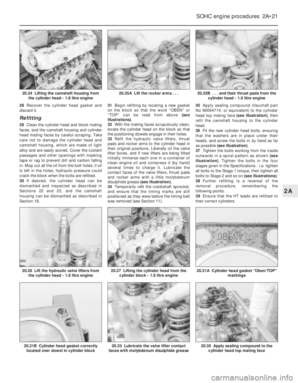
cylinder head (see illustration). If necessary,
tap the housing gently with a soft-faced mallet
to free it from the cylinder head, but do not
lever at the mating faces. Note that the
camshaft housing is located on dowels.
25Lift the rocker arms and their thrust pads
from the cylinder head, keeping them in order
so that they can be refitted in their original
positions (see illustrations).
26Lift the hydraulic valve lifters from the
cylinder head, and place them upright in an oil
bath until they are to be refitted (see
illustration). Ensure that the depth of oil is
sufficient to fully cover the valve lifters, and
keep the lifters in order, so that they can be
refitted in their original positions.
27Lift the cylinder head from the cylinder
block (see illustration). If necessary, tap the
cylinder head gently with a soft-faced mallet
to free it from the block, but do not lever at the
mating faces. Note that the cylinder head is
located on dowels.
2A•20SOHC engine procedures
20.7 Disconnecting a camshaft cover
breather hose -
2.0 litre engine20.11 Disconnecting the crankcase
breather tube stub hose -
1.6 litre engine
20.23 Cylinder head bolt loosening
sequence - SOHC engines20.19B Unbolting the crankcase breather
tube bracket from the cylinder head -
2.0 litre model20.19A Disconnecting the crankcase
breather tube stub hose -
2.0 litre engine
20.10 Unbolting the fuel injection wiring
harness earth leads from the camshaft
housing - 2.0 litre engine
Page 218 of 525
28Recover the cylinder head gasket and
discard it.
Refitting
29Clean the cylinder head and block mating
faces, and the camshaft housing and cylinder
head mating faces by careful scraping. Take
care not to damage the cylinder head and
camshaft housing, which are made of light
alloy and are easily scored. Cover the coolant
passages and other openings with masking
tape or rag to prevent dirt and carbon falling
in. Mop out all the oil from the bolt holes; if oil
is left in the holes, hydraulic pressure could
crack the block when the bolts are refitted.
30If desired, the cylinder head can be
dismantled and inspected as described in
Sections 22 and 23, and the camshaft
housing can be dismantled as described in
Section 18.31Begin refitting by locating a new gasket
on the block so that the word “OBEN” or
“TOP” can be read from above (see
illustrations).
32With the mating faces scrupulously clean,
locate the cylinder head on the block so that
the positioning dowels engage in their holes.
33Refit the hydraulic valve lifters, thrust
pads and rocker arms to the cylinder head in
their original positions. Liberally oil the valve
lifter bores, and if new lifters are being fitted
initially immerse each one in a container of
clean engine oil and compress it (by hand)
several times to charge it. Lubricate the
contact faces of the valve lifters, thrust pads
and rocker arms with a little molybdenum
disulphide grease (see illustration).
34Temporarily refit the crankshaft sprocket,
and ensure that the timing marks are still
positioned as they were before the timing belt
was removed (see Section 11).35Apply sealing compound (Vauxhall part
No 90094714, or equivalent) to the cylinder
head top mating face (see illustration), then
refit the camshaft housing to the cylinder
head.
36Fit the new cylinder head bolts, ensuring
that the washers are in place under their
heads, and screw the bolts in by hand as far
as possible (see illustration).
37Tighten the bolts working from the inside
outwards in a spiral pattern as shown (see
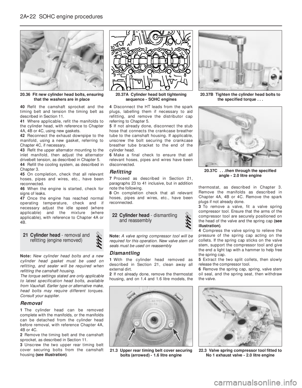
illustration). Tighten the bolts in the four
stages given in the Specifications -i.e. tighten
all bolts to the Stage 1 torque, then tighten all
bolts to Stage 2 and so on (see illustrations).
38Further refitting is a reversal of the
removal procedure, remembering the
following points.
39Ensure that the HT leads are refitted to
their correct cylinders.
SOHC engine procedures 2A•21
20.25B . . . and their thrust pads from the
cylinder head - 1.6 litre engine
20.35 Apply sealing compound to the
cylinder head top mating face20.33 Lubricate the valve lifter contact
faces with molybdenum disulphide grease20.31B Cylinder head gasket correctly
located over dowel in cylinder block
20.31A Cylinder head gasket “Oben/TOP”
markings20.27 Lifting the cylinder head from the
cylinder block - 1.6 litre engine20.26 Lift the hydraulic valve lifters from
the cylinder head - 1.6 litre engine
20.25A Lift the rocker arms . . .20.24 Lifting the camshaft housing from
the cylinder head - 1.6 litre engine
2A
Page 219 of 525
40Refit the camshaft sprocket and the
timing belt and tension the timing belt as
described in Section 11.
41Where applicable, refit the manifolds to
the cylinder head, with reference to Chapter
4A, 4B or 4C, using new gaskets.
42Reconnect the exhaust downpipe to the
manifold, using a new gasket, referring to
Chapter 4C, if necessary.
43Refit the upper alternator mounting to the
inlet manifold, then adjust the alternator
drivebelt tension, as described in Chapter 5.
44Refill the cooling system, as described in
Chapter 3.
45On completion, check that all relevant
hoses, pipes and wires, etc., have been
reconnected.
46When the engine is started, check for
signs of leaks.
47Once the engine has reached normal
operating temperature, check and if
necessary adjust the idle speed (where
applicable) and the mixture (where
applicable), with reference to Chapter 4A or
4B.
21Cylinder head - removal and
refitting (engine removed)
4
Note: New cylinder head bolts and a new
cylinder head gasket must be used on
refitting, and sealer will be required when
refitting the camshaft housing.
The torque settings stated are only applicable
to latest specification head bolts, available
from Vauxhall. Earlier type or alternative make,
head bolts may require different torques.
Consult your supplier.
Removal
1The cylinder head can be removed
complete with the manifolds, or the manifolds
can be detached from the cylinder head
before removal, with reference Chapter 4A,
4B or 4C.
2Remove the timing belt and the camshaft
sprocket, as described in Section 11.
3Unscrew the two upper rear timing belt
cover securing bolts from the camshaft
housing (see illustration).4Disconnect the HT leads from the spark
plugs, labelling them if necessary to aid
refitting, and remove the distributor cap
referring to Chapter 5.
5If not already done, disconnect the stub
hose that connects the crankcase breather
tube to the camshaft housing. If applicable,
unscrew the bolt securing the crankcase
breather tube bracket to the end of the
cylinder head.
6Make a final check to ensure that all
relevant hoses, pipes and wires have been
disconnected.
Refitting
7Proceed as described in Section 21,
paragraphs 23 to 41 inclusive, but in addition
note the following.
8On completion check that all relevant
hoses, pipes and wires, etc., have been
reconnected.
22Cylinder head -dismantling
and reassembly
4
Note: A valve spring compressor tool will be
required for this operation. New valve stem oil
seals must be used on reassembly
Dismantling
1With the cylinder head removed as
described in Section 21, clean away all
external dirt.
2If not already done, remove the thermostat
housing, and on 1.4 and 1.6 litre models, thethermostat, as described in Chapter 3.
Remove the manifolds as described in
Chapter 4A, 4B or 4C. Remove the spark
plugs if not already done.
3To remove a valve, fit a valve spring
compressor tool. Ensure that the arms of the
compressor tool are securely positioned on
the head of the valve and the spring cap (see
illustration).
4Compress the valve spring to relieve the
pressure of the spring cap acting on the
collets. If the spring cap sticks on the valve
stem, support the compressor tool and give
the end a light tap with a hammer to help free
the spring cap.
5Extract the two split collets, then slowly
release the compressor tool.
6Remove the spring cap, spring, valve stem
oil seal, and the spring seat, then withdraw
the valve.
2A•22SOHC engine procedures
20.36 Fit new cylinder head bolts, ensuring
that the washers are in place20.37B Tighten the cylinder head bolts to
the specified torque . . .
22.3 Valve spring compressor tool fitted to
No 1 exhaust valve - 2.0 litre engine21.3 Upper rear timing belt cover securing
bolts (arrowed) - 1.6 litre engine
20.37C . . .then through the specified
angle - 2.0 litre engine
20.37A Cylinder head bolt tightening
sequence - SOHC engines