1988 OPEL CALIBRA fold seats
[x] Cancel search: fold seatsPage 12 of 525

Refitting
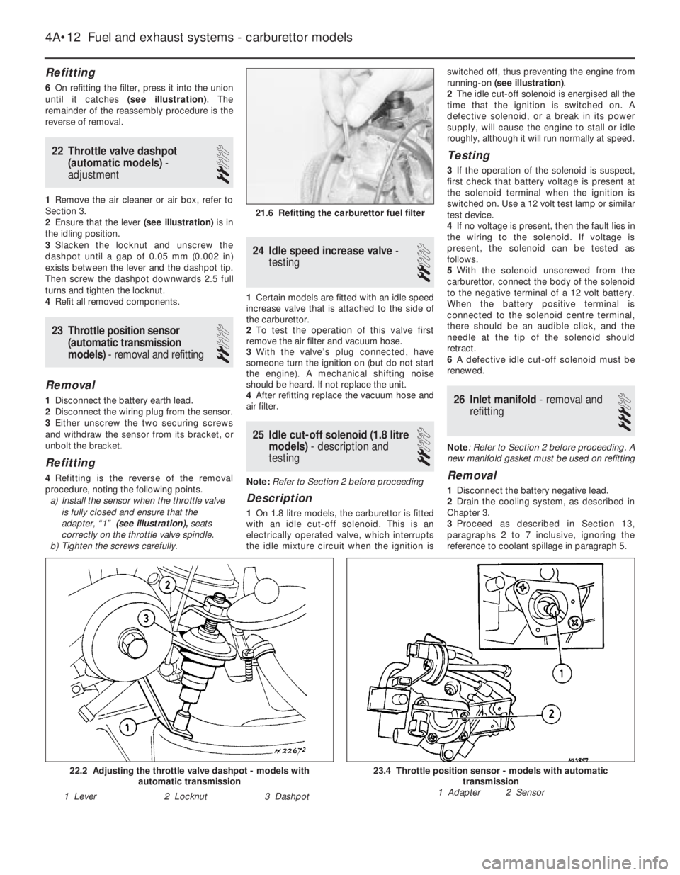
6On refitting the filter, press it into the union
until it catches (see illustration). The
remainder of the reassembly procedure is the
reverse of removal.
22Throttle valve dashpot
(automatic models) -
adjustment
2
1Remove the air cleaner or air box, refer to
Section 3.
2Ensure that the lever (see illustration)is in
the idling position.
3Slacken the locknut and unscrew the
dashpot until a gap of 0.05 mm (0.002 in)
exists between the lever and the dashpot tip.
Then screw the dashpot downwards 2.5 full
turns and tighten the locknut.
4Refit all removed components.
23Throttle position sensor
(automatic transmission
models) - removal and refitting
2
Removal
1Disconnect the battery earth lead.
2Disconnect the wiring plug from the sensor.
3Either unscrew the two securing screws
and withdraw the sensor from its bracket, or
unbolt the bracket.
Refitting
4Refitting is the reverse of the removal
procedure, noting the following points.
a)Install the sensor when the throttle valve
is fully closed and ensure that the
adapter, “1” (see illustration),seats
correctly on the throttle valve spindle.
b)Tighten the screws carefully.
24Idle speed increase valve -
testing
2
1Certain models are fitted with an idle speed
increase valve that is attached to the side of
the carburettor.
2To test the operation of this valve first
remove the air filter and vacuum hose.
3With the valve’s plug connected, have
someone turn the ignition on (but do not start
the engine). A mechanical shifting noise
should be heard. If not replace the unit.
4After refitting replace the vacuum hose and
air filter.
25Idle cut-off solenoid (1.8 litre
models) - description and
testing
2
Note: Refer to Section 2 before proceeding
Description
1On 1.8 litre models, the carburettor is fitted
with an idle cut-off solenoid. This is an
electrically operated valve, which interrupts
the idle mixture circuit when the ignition isswitched off, thus preventing the engine from
running-on (see illustration).
2The idle cut-off solenoid is energised all the
time that the ignition is switched on. A
defective solenoid, or a break in its power
supply, will cause the engine to stall or idle
roughly, although it will run normally at speed.
Testing
3If the operation of the solenoid is suspect,
first check that battery voltage is present at
the solenoid terminal when the ignition is
switched on. Use a 12 volt test lamp or similar
test device.
4If no voltage is present, then the fault lies in
the wiring to the solenoid. If voltage is
present, the solenoid can be tested as
follows.
5With the solenoid unscrewed from the
carburettor, connect the body of the solenoid
to the negative terminal of a 12 volt battery.
When the battery positive terminal is
connected to the solenoid centre terminal,
there should be an audible click, and the
needle at the tip of the solenoid should
retract.
6A defective idle cut-off solenoid must be
renewed.
26Inlet manifold - removal and
refitting
3
Note: Refer to Section 2 before proceeding. A
new manifold gasket must be used on refitting
Removal
1Disconnect the battery negative lead.
2Drain the cooling system, as described in
Chapter 3.
3Proceed as described in Section 13,
paragraphs 2 to 7 inclusive, ignoring the
reference to coolant spillage in paragraph 5.
4A•12Fuel and exhaust systems - carburettor models
21.6 Refitting the carburettor fuel filter
23.4 Throttle position sensor - models with automatic
transmission
1 Adapter 2 Sensor22.2 Adjusting the throttle valve dashpot - models with
automatic transmission
1 Lever2 Locknut3 Dashpot
Page 36 of 525

12•22Body electrical systems
Explanations of abbreviations used in wiring diagrams
ABSAnti-lock braking system
ACAir conditioning
AZVTrailer hitch
ATAutomatic transmission
ATCAutomatic temperature control
BRTrip (on-board) computer
CCCheck control system
CRCCruise control
DDiesel
DSTheft protection
DTTurbo Diesel
DWAAnti-theft warning system
DZMTachometer
EFCElectric folding roof (Convertible)
EKSPinch guard (electric windows)
EMPRadio
EUREuronorm (emission control standard)
engine
EZ + ElPlus ignition system (with self-
diagnosis)
EZVEcotronic
FHElectric windows
GBGreat Britain
HSHeated rear window
HWRear window wiper
HZGHeating
HRLLuggage compartment lampINSInstrument panel
IRLCourtesy lamps
KATCatalytic converter
KBSWiring harness
KVContact breaker distributor
L3.1Bosch Jetronic fuel injection system
LCDLiquid crystal display (LCD)
instruments
LHDLeft-hand drive
4WDFour-wheel-drive
LWRHeadlamp aim adjustment
M1.5Bosch Motronic M1.5 engine
management system
M2.5Bosch Motronic M2.5 engine
management system
MOTMotronic (general)
MTManual gearbox
MULMultec fuel injection system
NNorway
NSFront foglamps
NSLRear foglamps
OELOil level/pressure check system
OPTOptional equipment
PBSLPark and brake shift block
(automatic transmission, selector
lever in position ‘P’)P/NPark/neutral (automatic transmission)
POTPotentiometer
RCRear suspension level control
system
RFSReversing lamps
RHDRight-hand drive
SSweden
SDSunroof
SHHeated seats
SRAHeadlamp washers and wipers
TANKFuel level sender unit
TDTurbo Diesel
TEMPTemperature gauge
TFLDaytime driving lamps
TKSCourtesy lamp (door pillar) switches
TSZITransistorised ignition (inductive-
triggered) system
VGSCarburettor
WEGOdometer frequency/roadspeed
sensor
WHRRear suspension level control
system
WSWarning buzzer
ZVCentral locking
ZYLCylinder
Colour codes
BLBlue
HBLLight blue
BRBrown
GEYellow
GRGrey
GNGreenRTRed
WSWhite
SWBlack
LILilac
VIViolet
Wiring identification
Example: GEWS 1.5
GE -Wire basic colour
WS -Wire tracer colour
1.5 -Wire cross-section in mm
2
Note: Not all items shown are fitted to all models. Refer to Section 62 (Chapter 12) for details of diagram usage.
Page 123 of 525

Refitting
10Refitting is a reversal of removal, but
where applicable, refit the sunroof crank drive,
as described in Section 34.
40Seats (without tensioners) -
removal and refitting
3
Front seats
Removal
1Remove the single securing screw from the
front edge of the outer seat rail trim, then
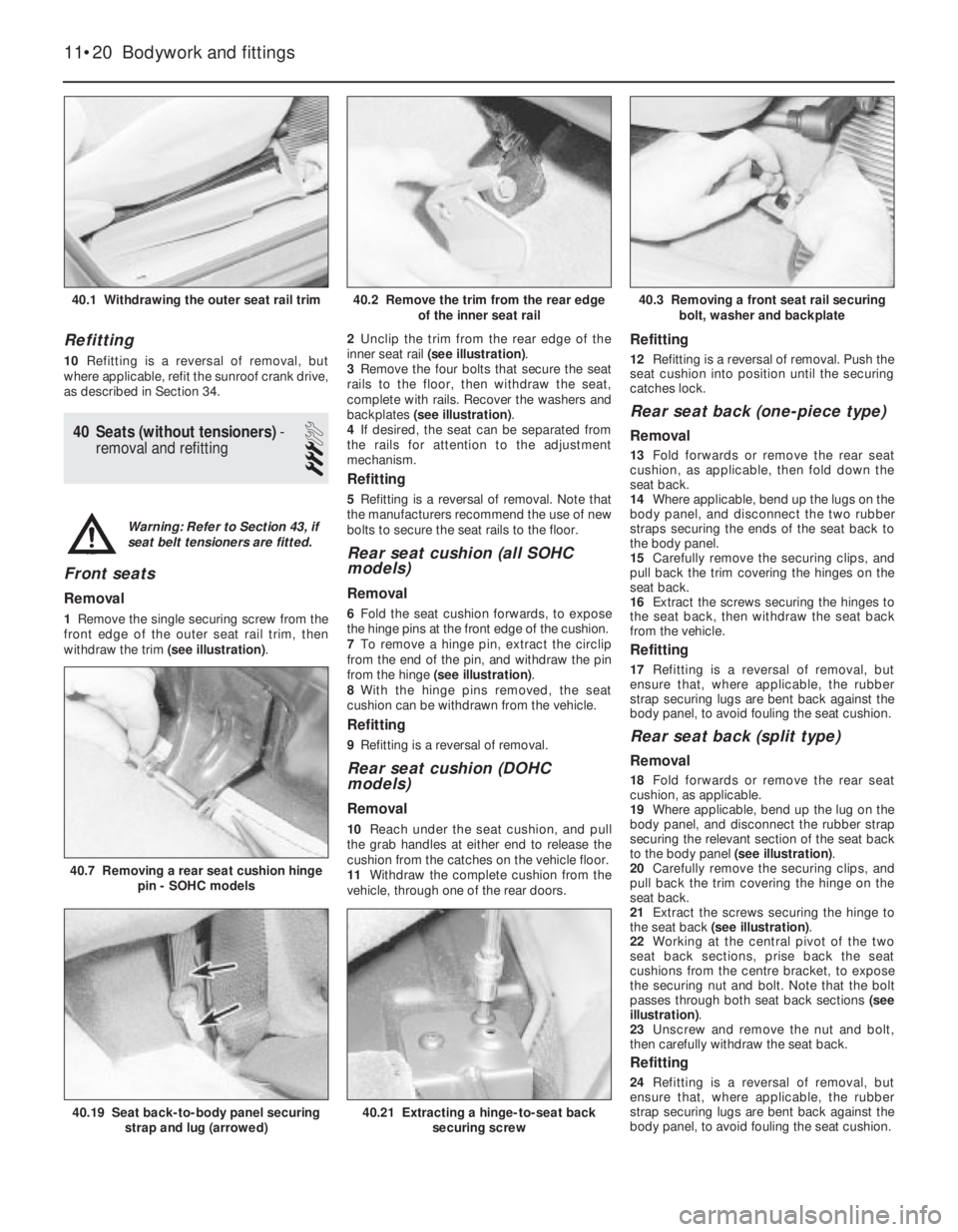
withdraw the trim (see illustration).2Unclip the trim from the rear edge of the
inner seat rail (see illustration).
3Remove the four bolts that secure the seat
rails to the floor, then withdraw the seat,
complete with rails. Recover the washers and
backplates (see illustration).
4If desired, the seat can be separated from
the rails for attention to the adjustment
mechanism.
Refitting
5Refitting is a reversal of removal. Note that
the manufacturers recommend the use of new
bolts to secure the seat rails to the floor.
Rear seat cushion (all SOHC
models)
Removal
6Fold the seat cushion forwards, to expose
the hinge pins at the front edge of the cushion.
7To remove a hinge pin, extract the circlip
from the end of the pin, and withdraw the pin
from the hinge (see illustration).
8With the hinge pins removed, the seat
cushion can be withdrawn from the vehicle.
Refitting
9Refitting is a reversal of removal.
Rear seat cushion (DOHC
models)
Removal
10Reach under the seat cushion, and pull
the grab handles at either end to release the
cushion from the catches on the vehicle floor.
11Withdraw the complete cushion from the
vehicle, through one of the rear doors.
Refitting
12Refitting is a reversal of removal. Push the
seat cushion into position until the securing
catches lock.
Rear seat back (one-piece type)
Removal
13Fold forwards or remove the rear seat
cushion, as applicable, then fold down the
seat back.
14Where applicable, bend up the lugs on the
body panel, and disconnect the two rubber
straps securing the ends of the seat back to
the body panel.
15Carefully remove the securing clips, and
pull back the trim covering the hinges on the
seat back.
16Extract the screws securing the hinges to
the seat back, then withdraw the seat back
from the vehicle.
Refitting
17Refitting is a reversal of removal, but
ensure that, where applicable, the rubber
strap securing lugs are bent back against the
body panel, to avoid fouling the seat cushion.
Rear seat back (split type)
Removal
18Fold forwards or remove the rear seat
cushion, as applicable.
19Where applicable, bend up the lug on the
body panel, and disconnect the rubber strap
securing the relevant section of the seat back
to the body panel (see illustration).
20Carefully remove the securing clips, and
pull back the trim covering the hinge on the
seat back.
21Extract the screws securing the hinge to
the seat back (see illustration).
22Working at the central pivot of the two
seat back sections, prise back the seat
cushions from the centre bracket, to expose
the securing nut and bolt. Note that the bolt
passes through both seat back sections (see
illustration).
23Unscrew and remove the nut and bolt,
then carefully withdraw the seat back.
Refitting
24Refitting is a reversal of removal, but
ensure that, where applicable, the rubber
strap securing lugs are bent back against the
body panel, to avoid fouling the seat cushion.
11•20Bodywork and fittings
40.1 Withdrawing the outer seat rail trim40.3 Removing a front seat rail securing
bolt, washer and backplate
40.7 Removing a rear seat cushion hinge
pin - SOHC models
40.21 Extracting a hinge-to-seat back
securing screw40.19 Seat back-to-body panel securing
strap and lug (arrowed)
40.2 Remove the trim from the rear edge
of the inner seat rail
Warning: Refer to Section 43, if
seat belt tensioners are fitted.
Page 169 of 525

b)Check the throttle cable operation and
adjustment (see above).
c)When reconnecting the vacuum hoses
and pipes, ensure that they are connected
to the front unions as shown in the
accompanying photograph.
d)As no fuel vapour trap is fitted, it is
essential that the manifold absolute
pressure sensor vacuum hose is routed
so that it falls steadily from the sensor to
the throttle body. This precaution will
prevent any fuel droplets being trapped in
the sensor or hose and allowing them to
drain into the inlet port.
e)Ensure that the fuel hoses are correctly
reconnected; the feed hose is on the
injector end of the throttle body.
f)Switch on the ignition and check for signs
of fuel leaks from all disturbed unions; if
any signs of leakage are detected, the
problem must be rectified before the
engine is started.
33Idle air control stepper
motor - removal and refitting
3
Removal
1Remove the air box (see Section 5).
2Disconnect the battery earth lead.3Disconnect the wiring plug from the stepper
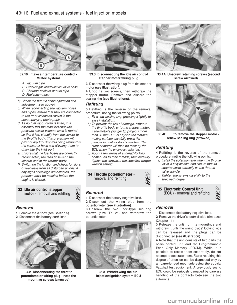
motor (see illustration).
4Undo its two screws, then withdraw the
stepper motor. Remove and discard the
sealing ring (see illustrations).
Refitting
5Refitting is the reverse of the removal
procedure, noting the following points.
a)Fit a new sealing ring, greasing it lightly to
ease installation.
b)To prevent the risk of damage, either to
the throttle body or to the stepper motor,
if the motor’s plunger tip projects more
than 28 mm (1.1 in) beyond the motor’s
mating surface, carefully press the
plunger in until its stop is reached. The
stepper motor will then be reset by the
ECU when the engine is restarted.
c)Apply a few drops of a thread-locking
compound to their threads, then carefully
tighten the screws to the specified torque
wrench setting.
34Throttle potentiometer -
removal and refitting
3
Removal
1Disconnect the battery negative lead.
2Disconnect the wiring plug from the
potentiometer (see illustration).
3Unscrew the two Torx-type securing
screws (size TX 25) and withdraw the
potentiometer.
Refitting
4Refitting is the reverse of the removal
procedure, noting the following points.
a)Install the potentiometer when the throttle
valve is fully closed, and ensure that its
adapter seats correctly on the throttle
valve spindle.
b)Tighten the screws carefully to the
specified torque.
35Electronic Control Unit
(ECU) - removal and refitting
3
Removal
1Disconnect the battery negative lead.
2Remove the driver’s footwell side trim panel
(Chapter 11).
3Release the unit from its mountings and
withdraw it until the wiring plugs’ locking lugs
can be released and the plugs can be
disconnected (see illustration).
4Note that the unit consists of two parts the
basic control unit and the Programmable
Read Only Memory (PROM). While it is
possible to renew them separately, do not
attempt to separate them. Faults requiring this
degree of attention can be diagnosed only by
an experienced mechanic using the special
Vauxhall test equipment. A previously sound
ECU could be seriously damaged by careless
handling of the contacts between the two
sub-units.
4B•16Fuel and exhaust systems - fuel injection models
32.10 Intake air temperature control -
Multec systems
A Vacuum pipe
B Exhaust gas recirculation valve hose
C Charcoal canister control pipe
D Fuel return hose
33.4A Unscrew retaining screws (second
screw arrowed) . . .
35.3 Withdrawing the fuel
injection/ignition system ECU34.2 Disconnecting the throttle
potentiometer wiring plug - note the
mounting screws (arrowed)
33.4B . . . to remove the stepper motor -
renew sealing ring (arrowed)
33.3 Disconnecting the idle air control
stepper motor wiring plug