1988 OPEL CALIBRA seat memory
[x] Cancel search: seat memoryPage 33 of 525

53Anti-theft alarm - general
1Certain models are fitted with an anti-theft
alarm as standard equipment.
2The alarm system is triggered by door,
bonnet and boot lid/tailgate mounted
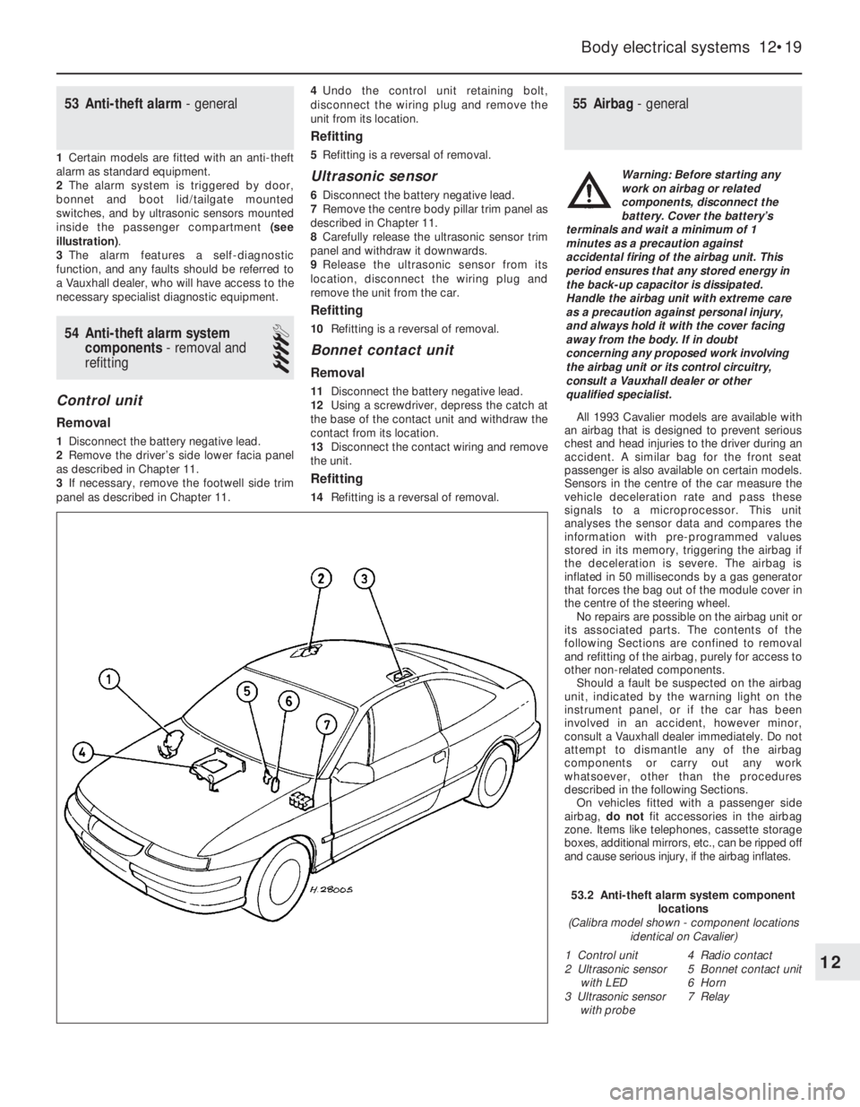
switches, and by ultrasonic sensors mounted
inside the passenger compartment (see
illustration).
3The alarm features a self-diagnostic
function, and any faults should be referred to
a Vauxhall dealer, who will have access to the
necessary specialist diagnostic equipment.
54Anti-theft alarm system
components -removal and
refitting
4
Control unit
Removal
1Disconnect the battery negative lead.
2Remove the driver’s side lower facia panel
as described in Chapter 11.
3If necessary, remove the footwell side trim
panel as described in Chapter 11.4Undo the control unit retaining bolt,
disconnect the wiring plug and remove the
unit from its location.
Refitting
5Refitting is a reversal of removal.
Ultrasonic sensor
6Disconnect the battery negative lead.
7Remove the centre body pillar trim panel as
described in Chapter 11.
8Carefully release the ultrasonic sensor trim
panel and withdraw it downwards.
9Release the ultrasonic sensor from its
location, disconnect the wiring plug and
remove the unit from the car.
Refitting
10Refitting is a reversal of removal.
Bonnet contact unit
Removal
11Disconnect the battery negative lead.
12Using a screwdriver, depress the catch at
the base of the contact unit and withdraw the
contact from its location.
13Disconnect the contact wiring and remove
the unit.
Refitting
14Refitting is a reversal of removal.
55Airbag - general
All 1993 Cavalier models are available with
an airbag that is designed to prevent serious
chest and head injuries to the driver during an
accident. A similar bag for the front seat
passenger is also available on certain models.
Sensors in the centre of the car measure the
vehicle deceleration rate and pass these
signals to a microprocessor. This unit
analyses the sensor data and compares the
information with pre-programmed values
stored in its memory, triggering the airbag if
the deceleration is severe. The airbag is
inflated in 50 milliseconds by a gas generator
that forces the bag out of the module cover in
the centre of the steering wheel.
No repairs are possible on the airbag unit or
its associated parts. The contents of the
following Sections are confined to removal
and refitting of the airbag, purely for access to
other non-related components.
Should a fault be suspected on the airbag
unit, indicated by the warning light on the
instrument panel, or if the car has been
involved in an accident, however minor,
consult a Vauxhall dealer immediately. Do not
attempt to dismantle any of the airbag
components or carry out any work
whatsoever, other than the procedures
described in the following Sections.
On vehicles fitted with a passenger side
airbag, do notfit accessories in the airbag
zone. Items like telephones, cassette storage
boxes, additional mirrors, etc., can be ripped off
and cause serious injury, if the airbag inflates.
Body electrical systems 12•19
12
53.2 Anti-theft alarm system component
locations
(Calibra model shown - component locations
identical on Cavalier)
1 Control unit
2 Ultrasonic sensor
with LED
3 Ultrasonic sensor
with probe4 Radio contact
5 Bonnet contact unit
6 Horn
7 Relay
Warning: Before starting any
work on airbag or related
components, disconnect the
battery. Cover the battery’s
terminals and wait a minimum of 1
minutes as a precaution against
accidental firing of the airbag unit. This
period ensures that any stored energy in
the back-up capacitor is dissipated.
Handle the airbag unit with extreme care
as a precaution against personal injury,
and always hold it with the cover facing
away from the body. If in doubt
concerning any proposed work involving
the airbag unit or its control circuitry,
consult a Vauxhall dealer or other
qualified specialist.
Page 169 of 525

b)Check the throttle cable operation and
adjustment (see above).
c)When reconnecting the vacuum hoses
and pipes, ensure that they are connected
to the front unions as shown in the
accompanying photograph.
d)As no fuel vapour trap is fitted, it is
essential that the manifold absolute
pressure sensor vacuum hose is routed
so that it falls steadily from the sensor to
the throttle body. This precaution will
prevent any fuel droplets being trapped in
the sensor or hose and allowing them to
drain into the inlet port.
e)Ensure that the fuel hoses are correctly
reconnected; the feed hose is on the
injector end of the throttle body.
f)Switch on the ignition and check for signs
of fuel leaks from all disturbed unions; if
any signs of leakage are detected, the
problem must be rectified before the
engine is started.
33Idle air control stepper
motor - removal and refitting
3
Removal
1Remove the air box (see Section 5).
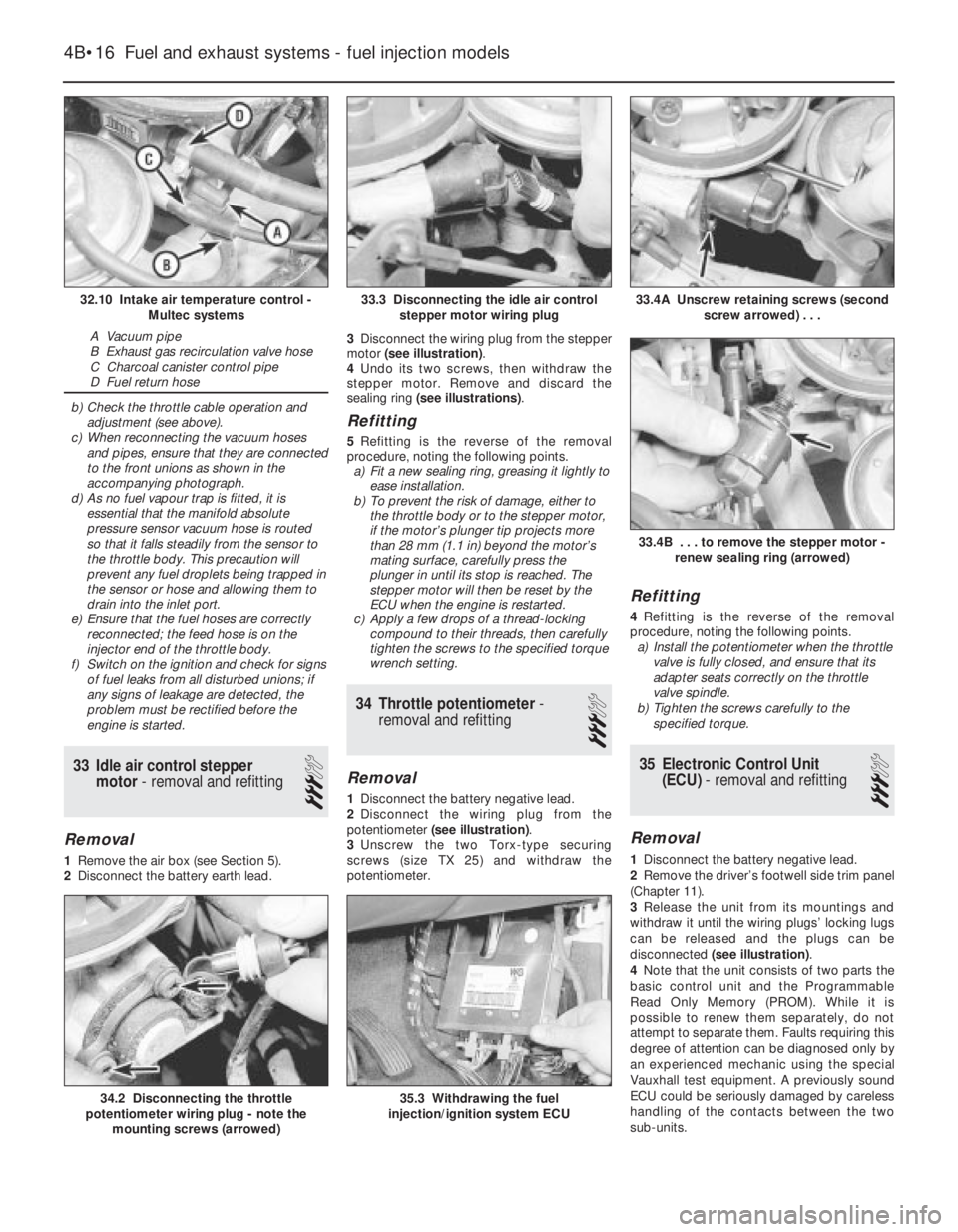
2Disconnect the battery earth lead.3Disconnect the wiring plug from the stepper
motor (see illustration).
4Undo its two screws, then withdraw the
stepper motor. Remove and discard the
sealing ring (see illustrations).
Refitting
5Refitting is the reverse of the removal
procedure, noting the following points.
a)Fit a new sealing ring, greasing it lightly to
ease installation.
b)To prevent the risk of damage, either to
the throttle body or to the stepper motor,
if the motor’s plunger tip projects more
than 28 mm (1.1 in) beyond the motor’s
mating surface, carefully press the
plunger in until its stop is reached. The
stepper motor will then be reset by the
ECU when the engine is restarted.
c)Apply a few drops of a thread-locking
compound to their threads, then carefully
tighten the screws to the specified torque
wrench setting.
34Throttle potentiometer -
removal and refitting
3
Removal
1Disconnect the battery negative lead.
2Disconnect the wiring plug from the
potentiometer (see illustration).
3Unscrew the two Torx-type securing
screws (size TX 25) and withdraw the
potentiometer.
Refitting
4Refitting is the reverse of the removal
procedure, noting the following points.
a)Install the potentiometer when the throttle
valve is fully closed, and ensure that its
adapter seats correctly on the throttle
valve spindle.
b)Tighten the screws carefully to the
specified torque.
35Electronic Control Unit
(ECU) - removal and refitting
3
Removal
1Disconnect the battery negative lead.
2Remove the driver’s footwell side trim panel
(Chapter 11).
3Release the unit from its mountings and
withdraw it until the wiring plugs’ locking lugs
can be released and the plugs can be
disconnected (see illustration).
4Note that the unit consists of two parts the
basic control unit and the Programmable
Read Only Memory (PROM). While it is
possible to renew them separately, do not
attempt to separate them. Faults requiring this
degree of attention can be diagnosed only by
an experienced mechanic using the special
Vauxhall test equipment. A previously sound
ECU could be seriously damaged by careless
handling of the contacts between the two
sub-units.
4B•16Fuel and exhaust systems - fuel injection models
32.10 Intake air temperature control -
Multec systems
A Vacuum pipe
B Exhaust gas recirculation valve hose
C Charcoal canister control pipe
D Fuel return hose
33.4A Unscrew retaining screws (second
screw arrowed) . . .
35.3 Withdrawing the fuel
injection/ignition system ECU34.2 Disconnecting the throttle
potentiometer wiring plug - note the
mounting screws (arrowed)
33.4B . . . to remove the stepper motor -
renew sealing ring (arrowed)
33.3 Disconnecting the idle air control
stepper motor wiring plug