1988 OPEL CALIBRA instrument panel
[x] Cancel search: instrument panelPage 5 of 525

10Throttle pedal - removal and
refitting
3
Removal
1Working inside the vehicle, remove the
lower trim panel from the driver’s footwell.
2Slide the cable retainer from the bracket on
the top of the pedal, and disconnect the cable
end from the pedal.
3Extract the circlip from the right-hand end
of the pedal pivot shaft, then slide out the
pivot shaft from the left-hand side of the pivot
bracket (see illustration). Recover the pivot
bushes and the pedal return spring.
4Examine the pivot bushes for wear, and
renew if necessary.
Refitting
5Refitting is a reversal of removal, but on
completion check the throttle mechanism for
satisfactory operation, and check the throttle
cable adjustment, as described in Section 11.
11Throttle cable - removal,
refitting and adjustment
3
Removal
1Remove the air cleaner, on early models.
On later models, disconnect the air trunking
from the air cleaner, then disconnect the
vacuum pipe and breather hose from the airbox. Extract the three securing screws and lift
off the air box, complete with air trunking(see
illustration).
2Extract the clip from the cable end fitting at
the bracket on the carburettor, then slide the
cable end grommet from the bracket (see
illustrations).
3Slide the cable end from the throttle valve
lever on the carburettor.
4Working inside the vehicle, remove the
lower trim panel from the driver’s footwell.
5Slide the cable retainer from the bracket on
the top of the pedal, and disconnect the cable
end from the pedal.
6Make a careful note of the cable routing,
then withdraw the cable through the bulkhead
into the engine compartment.Refitting
7Refitting is a reversal of removal,
remembering the following points.
8Ensure that the cable is correctly routed, as
noted before removal.
9Ensure that the bulkhead grommet is
correctly seated in its hole.
Adjustment
10On completion, check the throttle
mechanism for satisfactory operation, and if
necessary adjust the cable, as described in
the following paragraphs.
11Two points of cable adjustment are
provided. A stop screw is located on the
pedal arm to control the fully released position
of the pedal stop (see illustration).A clip is
located on a threaded section of the cable
sheath at the bracket on the carburettor, to
adjust the cable free play.12The cable should be adjusted so that
when the throttle pedal is released, there is
very slight free play in the cable at the
carburettor end.
13Check that when the throttle pedal is fully
depressed, the throttle valve is fully open.
Adjust the position of the clip on the cable
sheath, and the pedal stop screw, to achieve
the desired results.
12Carburettor - general
1The Pierburg 2E3 carburettor is of twin-
venturi, fixed-jet sequential throttle type. The
primary throttle valve operates alone except
at high engine speeds and loads, when the
secondary throttle valve is operated, until at
full-throttle, both are fully open. This
arrangement allows good fuel economy
during light acceleration and cruising, but also
gives maximum power at full-throttle. The
secondary throttle valve is vacuum-operated,
according to the vacuum produced in the
primary venturi. The primary throttle barrel
and venturi diameters are smaller than their
secondary counterparts. The carburettor is a
complicated instrument, with various
refinements and sub-systems added to
achieve improved driveability, economy and
exhaust emission levels(see illustrations).
Fuel and exhaust systems - carburettor models 4A•5
11.2A Extract the throttle cable end
clip . . .
12.1A Side view of carburettor, showing
accelerator pump (1) and main choke pull-
down diaphragm unit (2)11.11 Throttle pedal stop screw11.2B . . .and slide the grommet from the
bracket
11.1 Removing an air box securing screw10.3 Throttle pedal pivot assembly. Circlip
arrowed
4A
Page 15 of 525
12
Wiper blades
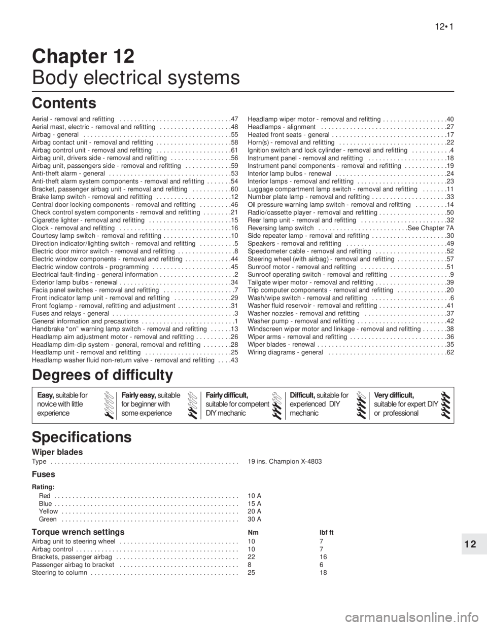
Type . . . . . . . . . . . . . . . . . . . . . . . . . . . . . . . . . . . . . . . . . . . . . . . . . . . . 19 ins. Champion X-4803
Fuses
Rating:
Red . . . . . . . . . . . . . . . . . . . . . . . . . . . . . . . . . . . . . . . . . . . . . . . . . . . 10 A
Blue . . . . . . . . . . . . . . . . . . . . . . . . . . . . . . . . . . . . . . . . . . . . . . . . . . . 15 A
Yellow . . . . . . . . . . . . . . . . . . . . . . . . . . . . . . . . . . . . . . . . . . . . . . . . . 20 A
Green . . . . . . . . . . . . . . . . . . . . . . . . . . . . . . . . . . . . . . . . . . . . . . . . . 30 A
Torque wrench settingsNm lbf ft
Airbag unit to steering wheel . . . . . . . . . . . . . . . . . . . . . . . . . . . . . . . . . 10 7
Airbag control . . . . . . . . . . . . . . . . . . . . . . . . . . . . . . . . . . . . . . . . . . . . . 10 7
Brackets, passenger airbag . . . . . . . . . . . . . . . . . . . . . . . . . . . . . . . . . . 22 16
Passenger airbag to bracket . . . . . . . . . . . . . . . . . . . . . . . . . . . . . . . . . 8 6
Steering to column . . . . . . . . . . . . . . . . . . . . . . . . . . . . . . . . . . . . . . . . . 25 18
Chapter 12
Body electrical systems
Aerial - removal and refitting . . . . . . . . . . . . . . . . . . . . . . . . . . . . . . .47
Aerial mast, electric - removal and refitting . . . . . . . . . . . . . . . . . . . .48
Airbag - general . . . . . . . . . . . . . . . . . . . . . . . . . . . . . . . . . . . . . . . . .55
Airbag contact unit - removal and refitting . . . . . . . . . . . . . . . . . . . . .58
Airbag control unit - removal and refitting . . . . . . . . . . . . . . . . . . . . .61
Airbag unit, drivers side - removal and refitting . . . . . . . . . . . . . . . . .56
Airbag unit, passengers side - removal and refitting . . . . . . . . . . . . .59
Anti-theft alarm - general . . . . . . . . . . . . . . . . . . . . . . . . . . . . . . . . . .53
Anti-theft alarm system components - removal and refitting . . . . . . .54
Bracket, passenger airbag unit - removal and refitting . . . . . . . . . . .60
Brake lamp switch - removal and refitting . . . . . . . . . . . . . . . . . . . . .12
Central door locking components - removal and refitting . . . . . . . . .46
Check control system components - removal and refitting . . . . . . . .21
Cigarette lighter - removal and refitting . . . . . . . . . . . . . . . . . . . . . . .15
Clock - removal and refitting . . . . . . . . . . . . . . . . . . . . . . . . . . . . . . .16
Courtesy lamp switch - removal and refitting . . . . . . . . . . . . . . . . . . .10
Direction indicator/lighting switch - removal and refitting . . . . . . . . . .5
Electric door mirror switch - removal and refitting . . . . . . . . . . . . . . . .8
Electric window components - removal and refitting . . . . . . . . . . . . .44
Electric window controls - programming . . . . . . . . . . . . . . . . . . . . . .45
Electrical fault-finding - general information . . . . . . . . . . . . . . . . . . . . .2
Exterior lamp bulbs - renewal . . . . . . . . . . . . . . . . . . . . . . . . . . . . . . .34
Facia panel switches - removal and refitting . . . . . . . . . . . . . . . . . . . .7
Front indicator lamp unit - removal and refitting . . . . . . . . . . . . . . . .29
Front foglamp - removal, refitting and adjustment . . . . . . . . . . . . . . .31
Fuses and relays - general . . . . . . . . . . . . . . . . . . . . . . . . . . . . . . . . . .3
General information and precautions . . . . . . . . . . . . . . . . . . . . . . . . . .1
Handbrake “on” warning lamp switch - removal and refitting . . . . . .13
Headlamp aim adjustment motor - removal and refitting . . . . . . . . . .26
Headlamp dim-dip system - general, removal and refitting . . . . . . . .28
Headlamp unit - removal and refitting . . . . . . . . . . . . . . . . . . . . . . . .25
Headlamp washer fluid non-return valve - removal and refitting . . . .43Headlamp wiper motor - removal and refitting . . . . . . . . . . . . . . . . . .40
Headlamps - alignment . . . . . . . . . . . . . . . . . . . . . . . . . . . . . . . . . . .27
Heated front seats - general . . . . . . . . . . . . . . . . . . . . . . . . . . . . . . . .17
Horn(s) - removal and refitting . . . . . . . . . . . . . . . . . . . . . . . . . . . . . .22
Ignition switch and lock cylinder - removal and refitting . . . . . . . . . . .4
Instrument panel - removal and refitting . . . . . . . . . . . . . . . . . . . . . .18
Instrument panel components - removal and refitting . . . . . . . . . . . .19
Interior lamp bulbs - renewal . . . . . . . . . . . . . . . . . . . . . . . . . . . . . . .24
Interior lamps - removal and refitting . . . . . . . . . . . . . . . . . . . . . . . . .23
Luggage compartment lamp switch - removal and refitting . . . . . . .11
Number plate lamp - removal and refitting . . . . . . . . . . . . . . . . . . . . .33
Oil pressure warning lamp switch - removal and refitting . . . . . . . . .14
Radio/cassette player - removal and refitting . . . . . . . . . . . . . . . . . . .50
Rear lamp unit - removal and refitting . . . . . . . . . . . . . . . . . . . . . . . .32
Reversing lamp switch . . . . . . . . . . . . . . . . . . . . . . . . .See Chapter 7A
Side repeater lamp - removal and refitting . . . . . . . . . . . . . . . . . . . . .30
Speakers - removal and refitting . . . . . . . . . . . . . . . . . . . . . . . . . . . .49
Speedometer cable - removal and refitting . . . . . . . . . . . . . . . . . . . .52
Steering wheel (with airbag) - removal and refitting . . . . . . . . . . . . . .57
Sunroof motor - removal and refitting . . . . . . . . . . . . . . . . . . . . . . . .51
Sunroof operating switch - removal and refitting . . . . . . . . . . . . . . . . .9
Tailgate wiper motor - removal and refitting . . . . . . . . . . . . . . . . . . . .39
Trip computer components - removal and refitting . . . . . . . . . . . . . .20
Wash/wipe switch - removal and refitting . . . . . . . . . . . . . . . . . . . . . .6
Washer fluid reservoir - removal and refitting . . . . . . . . . . . . . . . . . . .41
Washer nozzles - removal and refitting . . . . . . . . . . . . . . . . . . . . . . .37
Washer pump - removal and refitting . . . . . . . . . . . . . . . . . . . . . . . . .42
Windscreen wiper motor and linkage - removal and refitting . . . . . . .38
Wiper arms - removal and refitting . . . . . . . . . . . . . . . . . . . . . . . . . . .36
Wiper blades - renewal . . . . . . . . . . . . . . . . . . . . . . . . . . . . . . . . . . . .35
Wiring diagrams - general . . . . . . . . . . . . . . . . . . . . . . . . . . . . . . . . .62
12•1
Specifications Contents
Easy,suitable for
novice with little
experienceFairly easy,suitable
for beginner with
some experienceFairly difficult,
suitable for competent
DIY mechanic
Difficult,suitable for
experienced DIY
mechanicVery difficult,
suitable for expert DIY
or professional
Degrees of difficulty
54321
Page 20 of 525
3To remove the cigarette lighter assembly,
simply pull it from the illumination ring
assembly. If desired, the illumination ring
assembly can be removed, by pulling it from
the housing after depressing the retaining
clips.
Refitting
4Refitting is a reversal of removal.
16Clock - removal and refitting
2
Removal
1Disconnect the battery negative lead.
2Using a thin-bladed screwdriver, carefully
prise the clock from the facia panel.
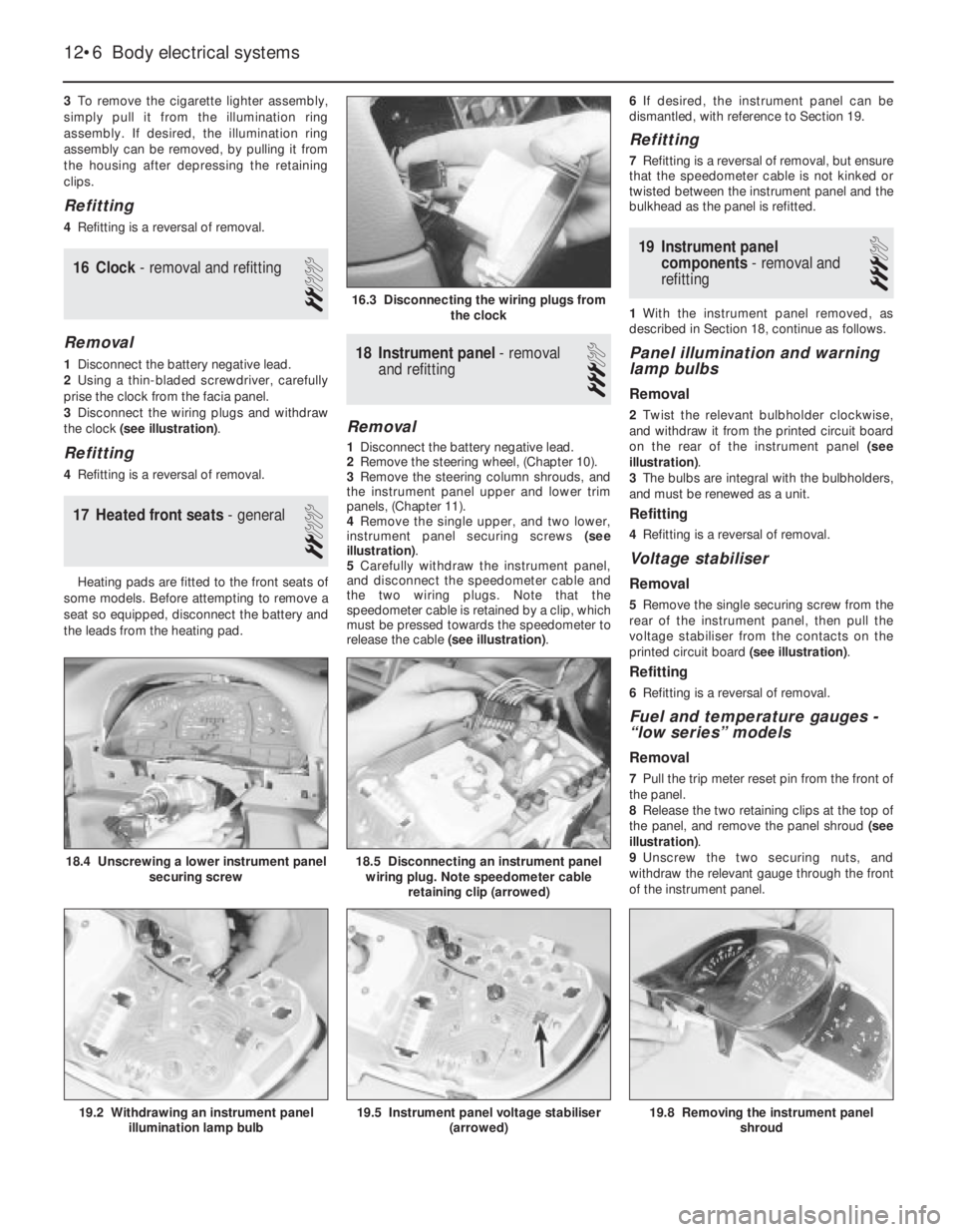
3Disconnect the wiring plugs and withdraw
the clock (see illustration).
Refitting
4Refitting is a reversal of removal.
17Heated front seats - general
2
Heating pads are fitted to the front seats of
some models. Before attempting to remove a
seat so equipped, disconnect the battery and
the leads from the heating pad.
18Instrument panel -removal
and refitting
3
Removal
1Disconnect the battery negative lead.
2Remove the steering wheel, (Chapter 10).
3Remove the steering column shrouds, and
the instrument panel upper and lower trim
panels, (Chapter 11).
4Remove the single upper, and two lower,
instrument panel securing screws (see
illustration).
5Carefully withdraw the instrument panel,
and disconnect the speedometer cable and
the two wiring plugs. Note that the
speedometer cable is retained by a clip, which
must be pressed towards the speedometer to
release the cable (see illustration).6If desired, the instrument panel can be
dismantled, with reference to Section 19.
Refitting
7Refitting is a reversal of removal, but ensure
that the speedometer cable is not kinked or
twisted between the instrument panel and the
bulkhead as the panel is refitted.
19Instrument panel
components - removal and
refitting
3
1With the instrument panel removed, as
described in Section 18, continue as follows.
Panel illumination and warning
lamp bulbs
Removal
2Twist the relevant bulbholder clockwise,
and withdraw it from the printed circuit board
on the rear of the instrument panel (see
illustration).
3The bulbs are integral with the bulbholders,
and must be renewed as a unit.
Refitting
4Refitting is a reversal of removal.
Voltage stabiliser
Removal
5Remove the single securing screw from the
rear of the instrument panel, then pull the
voltage stabiliser from the contacts on the
printed circuit board (see illustration).
Refitting
6Refitting is a reversal of removal.
Fuel and temperature gauges -
“low series” models
Removal
7Pull the trip meter reset pin from the front of
the panel.
8Release the two retaining clips at the top of
the panel, and remove the panel shroud (see
illustration).
9Unscrew the two securing nuts, and
withdraw the relevant gauge through the front
of the instrument panel.
12•6Body electrical systems
16.3 Disconnecting the wiring plugs from
the clock
18.5 Disconnecting an instrument panel
wiring plug. Note speedometer cable
retaining clip (arrowed)
19.8 Removing the instrument panel
shroud19.5 Instrument panel voltage stabiliser
(arrowed)19.2 Withdrawing an instrument panel
illumination lamp bulb
18.4 Unscrewing a lower instrument panel
securing screw
Page 21 of 525
Refitting
10Refitting is a reversal of removal.
Fuel and temperature gauge
assembly -“high series” models
11The procedure is as described in
paragraphs 7 to 10 inclusive, except that the
gauge assembly is secured by four nuts.
Tachometer
12The procedure is as described in
paragraphs 7 to 10 inclusive except that the
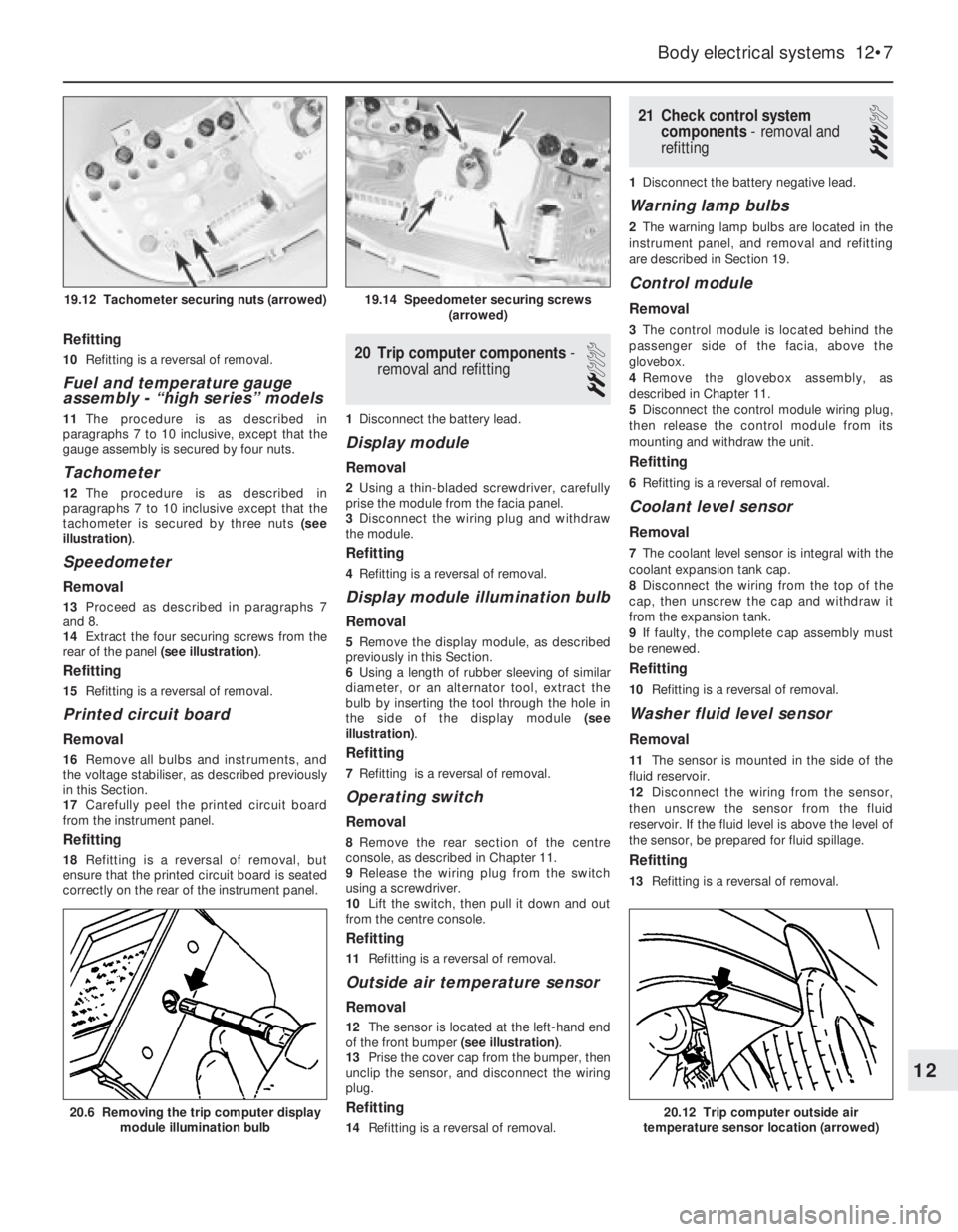
tachometer is secured by three nuts (see
illustration).
Speedometer
Removal
13Proceed as described in paragraphs 7
and 8.
14Extract the four securing screws from the
rear of the panel (see illustration).
Refitting
15Refitting is a reversal of removal.
Printed circuit board
Removal
16Remove all bulbs and instruments, and
the voltage stabiliser, as described previously
in this Section.
17Carefully peel the printed circuit board
from the instrument panel.
Refitting
18Refitting is a reversal of removal, but
ensure that the printed circuit board is seated
correctly on the rear of the instrument panel.
20Trip computer components -
removal and refitting
2
1Disconnect the battery lead.
Display module
Removal
2Using a thin-bladed screwdriver, carefully
prise the module from the facia panel.
3Disconnect the wiring plug and withdraw
the module.
Refitting
4Refitting is a reversal of removal.
Display module illumination bulb
Removal
5Remove the display module, as described
previously in this Section.
6Using a length of rubber sleeving of similar
diameter, or an alternator tool, extract the
bulb by inserting the tool through the hole in
the side of the display module (see
illustration).
Refitting
7Refitting is a reversal of removal.
Operating switch
Removal
8Remove the rear section of the centre
console, as described in Chapter 11.
9Release the wiring plug from the switch
using a screwdriver.
10Lift the switch, then pull it down and out
from the centre console.
Refitting
11Refitting is a reversal of removal.
Outside air temperature sensor
Removal
12The sensor is located at the left-hand end
of the front bumper (see illustration).
13Prise the cover cap from the bumper, then
unclip the sensor, and disconnect the wiring
plug.
Refitting
14Refitting is a reversal of removal.
21Check control system
components - removal and
refitting
3
1Disconnect the battery negative lead.
Warning lamp bulbs
2The warning lamp bulbs are located in the
instrument panel, and removal and refitting
are described in Section 19.
Control module
Removal
3The control module is located behind the
passenger side of the facia, above the
glovebox.
4Remove the glovebox assembly, as
described in Chapter 11.
5Disconnect the control module wiring plug,
then release the control module from its
mounting and withdraw the unit.
Refitting
6Refitting is a reversal of removal.
Coolant level sensor
Removal
7The coolant level sensor is integral with the
coolant expansion tank cap.
8Disconnect the wiring from the top of the
cap, then unscrew the cap and withdraw it
from the expansion tank.
9If faulty, the complete cap assembly must
be renewed.
Refitting
10Refitting is a reversal of removal.
Washer fluid level sensor
Removal
11The sensor is mounted in the side of the
fluid reservoir.
12Disconnect the wiring from the sensor,
then unscrew the sensor from the fluid
reservoir. If the fluid level is above the level of
the sensor, be prepared for fluid spillage.
Refitting
13Refitting is a reversal of removal.
Body electrical systems 12•7
20.6 Removing the trip computer display
module illumination bulb20.12 Trip computer outside air
temperature sensor location (arrowed)
19.14 Speedometer securing screws
(arrowed)19.12 Tachometer securing nuts (arrowed)
12
Page 32 of 525
6Remove the three securing screws, and
withdraw the speaker from the door.
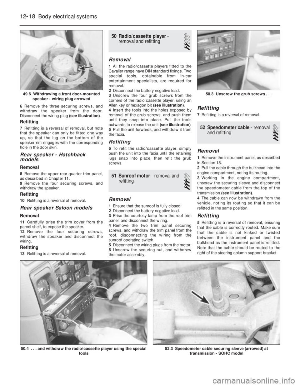
Disconnect the wiring plug (see illustration).
Refitting
7Refitting is a reversal of removal, but note
that the speaker can only be fitted one way
up, so that the lug on the bottom of the
speaker rim engages with the corresponding
hole in the door skin.
Rear speaker -Hatchback
models
Removal
8Remove the upper rear quarter trim panel,
as described in Chapter 11.
9Remove the four securing screws, and
withdraw the speaker.
Refitting
10Refitting is a reversal of removal.
Rear speaker Saloon models
Removal
11Carefully prise the trim cover from the
parcel shelf, to expose the speaker.
12Remove the four securing screws,
withdraw the speaker and disconnect the
wiring.
Refitting
13Refitting is a reversal of removal.
50Radio/cassette player -
removal and refitting
2
Removal
1All the radio/cassette players fitted to the
Cavalier range have DIN standard fixings. Two
special tools, obtainable from in-car
entertainment specialists, are required for
removal.
2Disconnect the battery negative lead.
3Unscrew the four grub screws from the
corners of the radio cassette player, using an
Allen key or hexagon bit (see illustration).
4Insert the tools into the holes exposed by
removal of the grub screws, and push them
until they snap into place. Pull the tools
outwards to release the unit (see illustration).
5Pull the unit forwards, and withdraw it from
the facia.
Refitting
6To refit the radio/cassette player, simply
push the unit into the facia until the retaining
lugs snap into place, then refit the grub
screws.
51Sunroof motor - removal and
refitting
3
Removal
1Ensure that the sunroof is fully closed.
2Disconnect the battery negative lead.
3Prise the courtesy lamp from the roof trim
panel, and disconnect the wiring.
4Remove the two trim panel securing
screws, and withdraw the trim panel from the
roof, disconnecting the wiring from the
sunroof operating switch.
5Disconnect the wiring plugs from the motor.
6Unscrew the securing nut, and withdraw
the motor assembly.
Refitting
7Refitting is a reversal of removal.
52Speedometer cable - removal
and refitting
3
Removal
1Remove the instrument panel, as described
in Section 18.
2Pull the cable through the bulkhead into the
engine compartment, noting its routing.
3Working in the engine compartment,
unscrew the securing sleeve and disconnect
the speedometer cable from the top of the
transmission (see illustration).
4The cable can now be withdrawn from the
vehicle, noting its routing so that it can be
refitted in the same position.
Refitting
5Refitting is a reversal of removal, ensuring
that the cable is correctly routed. Make sure
that the cable is not kinked or twisted
between the instrument panel and the
bulkhead as the instrument panel is refitted.
Note that the cable should be routed to the
right of the steering column support bracket.
12•18Body electrical systems
49.6 Withdrawing a front door-mounted
speaker - wiring plug arrowed
50.4 . . . and withdraw the radio/cassette player using the special
tools52.3 Speedometer cable securing sleeve (arrowed) at
transmission - SOHC model
50.3 Unscrew the grub screws . . .
Page 33 of 525
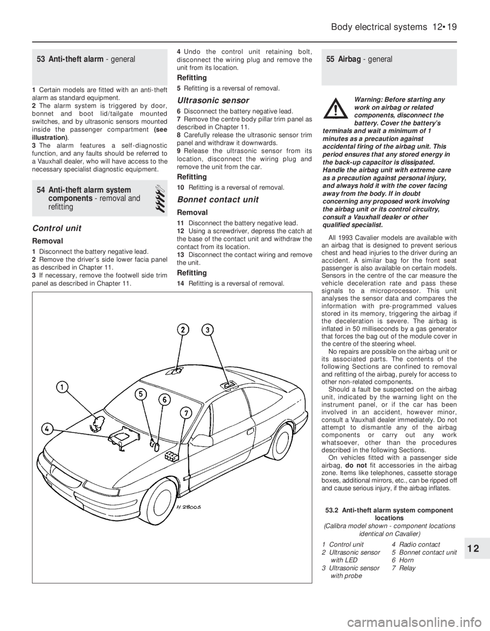
53Anti-theft alarm - general
1Certain models are fitted with an anti-theft
alarm as standard equipment.
2The alarm system is triggered by door,
bonnet and boot lid/tailgate mounted
switches, and by ultrasonic sensors mounted
inside the passenger compartment (see
illustration).
3The alarm features a self-diagnostic
function, and any faults should be referred to
a Vauxhall dealer, who will have access to the
necessary specialist diagnostic equipment.
54Anti-theft alarm system
components -removal and
refitting
4
Control unit
Removal
1Disconnect the battery negative lead.
2Remove the driver’s side lower facia panel
as described in Chapter 11.
3If necessary, remove the footwell side trim
panel as described in Chapter 11.4Undo the control unit retaining bolt,
disconnect the wiring plug and remove the
unit from its location.
Refitting
5Refitting is a reversal of removal.
Ultrasonic sensor
6Disconnect the battery negative lead.
7Remove the centre body pillar trim panel as
described in Chapter 11.
8Carefully release the ultrasonic sensor trim
panel and withdraw it downwards.
9Release the ultrasonic sensor from its
location, disconnect the wiring plug and
remove the unit from the car.
Refitting
10Refitting is a reversal of removal.
Bonnet contact unit
Removal
11Disconnect the battery negative lead.
12Using a screwdriver, depress the catch at
the base of the contact unit and withdraw the
contact from its location.
13Disconnect the contact wiring and remove
the unit.
Refitting
14Refitting is a reversal of removal.
55Airbag - general
All 1993 Cavalier models are available with
an airbag that is designed to prevent serious
chest and head injuries to the driver during an
accident. A similar bag for the front seat
passenger is also available on certain models.
Sensors in the centre of the car measure the
vehicle deceleration rate and pass these
signals to a microprocessor. This unit
analyses the sensor data and compares the
information with pre-programmed values
stored in its memory, triggering the airbag if
the deceleration is severe. The airbag is
inflated in 50 milliseconds by a gas generator
that forces the bag out of the module cover in
the centre of the steering wheel.
No repairs are possible on the airbag unit or
its associated parts. The contents of the
following Sections are confined to removal
and refitting of the airbag, purely for access to
other non-related components.
Should a fault be suspected on the airbag
unit, indicated by the warning light on the
instrument panel, or if the car has been
involved in an accident, however minor,
consult a Vauxhall dealer immediately. Do not
attempt to dismantle any of the airbag
components or carry out any work
whatsoever, other than the procedures
described in the following Sections.
On vehicles fitted with a passenger side
airbag, do notfit accessories in the airbag
zone. Items like telephones, cassette storage
boxes, additional mirrors, etc., can be ripped off
and cause serious injury, if the airbag inflates.
Body electrical systems 12•19
12
53.2 Anti-theft alarm system component
locations
(Calibra model shown - component locations
identical on Cavalier)
1 Control unit
2 Ultrasonic sensor
with LED
3 Ultrasonic sensor
with probe4 Radio contact
5 Bonnet contact unit
6 Horn
7 Relay
Warning: Before starting any
work on airbag or related
components, disconnect the
battery. Cover the battery’s
terminals and wait a minimum of 1
minutes as a precaution against
accidental firing of the airbag unit. This
period ensures that any stored energy in
the back-up capacitor is dissipated.
Handle the airbag unit with extreme care
as a precaution against personal injury,
and always hold it with the cover facing
away from the body. If in doubt
concerning any proposed work involving
the airbag unit or its control circuitry,
consult a Vauxhall dealer or other
qualified specialist.
Page 36 of 525

12•22Body electrical systems
Explanations of abbreviations used in wiring diagrams
ABSAnti-lock braking system
ACAir conditioning
AZVTrailer hitch
ATAutomatic transmission
ATCAutomatic temperature control
BRTrip (on-board) computer
CCCheck control system
CRCCruise control
DDiesel
DSTheft protection
DTTurbo Diesel
DWAAnti-theft warning system
DZMTachometer
EFCElectric folding roof (Convertible)
EKSPinch guard (electric windows)
EMPRadio
EUREuronorm (emission control standard)
engine
EZ + ElPlus ignition system (with self-
diagnosis)
EZVEcotronic
FHElectric windows
GBGreat Britain
HSHeated rear window
HWRear window wiper
HZGHeating
HRLLuggage compartment lampINSInstrument panel
IRLCourtesy lamps
KATCatalytic converter
KBSWiring harness
KVContact breaker distributor
L3.1Bosch Jetronic fuel injection system
LCDLiquid crystal display (LCD)
instruments
LHDLeft-hand drive
4WDFour-wheel-drive
LWRHeadlamp aim adjustment
M1.5Bosch Motronic M1.5 engine
management system
M2.5Bosch Motronic M2.5 engine
management system
MOTMotronic (general)
MTManual gearbox
MULMultec fuel injection system
NNorway
NSFront foglamps
NSLRear foglamps
OELOil level/pressure check system
OPTOptional equipment
PBSLPark and brake shift block
(automatic transmission, selector
lever in position ‘P’)P/NPark/neutral (automatic transmission)
POTPotentiometer
RCRear suspension level control
system
RFSReversing lamps
RHDRight-hand drive
SSweden
SDSunroof
SHHeated seats
SRAHeadlamp washers and wipers
TANKFuel level sender unit
TDTurbo Diesel
TEMPTemperature gauge
TFLDaytime driving lamps
TKSCourtesy lamp (door pillar) switches
TSZITransistorised ignition (inductive-
triggered) system
VGSCarburettor
WEGOdometer frequency/roadspeed
sensor
WHRRear suspension level control
system
WSWarning buzzer
ZVCentral locking
ZYLCylinder
Colour codes
BLBlue
HBLLight blue
BRBrown
GEYellow
GRGrey
GNGreenRTRed
WSWhite
SWBlack
LILilac
VIViolet
Wiring identification
Example: GEWS 1.5
GE -Wire basic colour
WS -Wire tracer colour
1.5 -Wire cross-section in mm
2
Note: Not all items shown are fitted to all models. Refer to Section 62 (Chapter 12) for details of diagram usage.
Page 117 of 525
9Where applicable, ensure that the glass
panel securing screw lockwashers engage
with the locating pins on the guide rails.
10Before fully tightening the glass panel
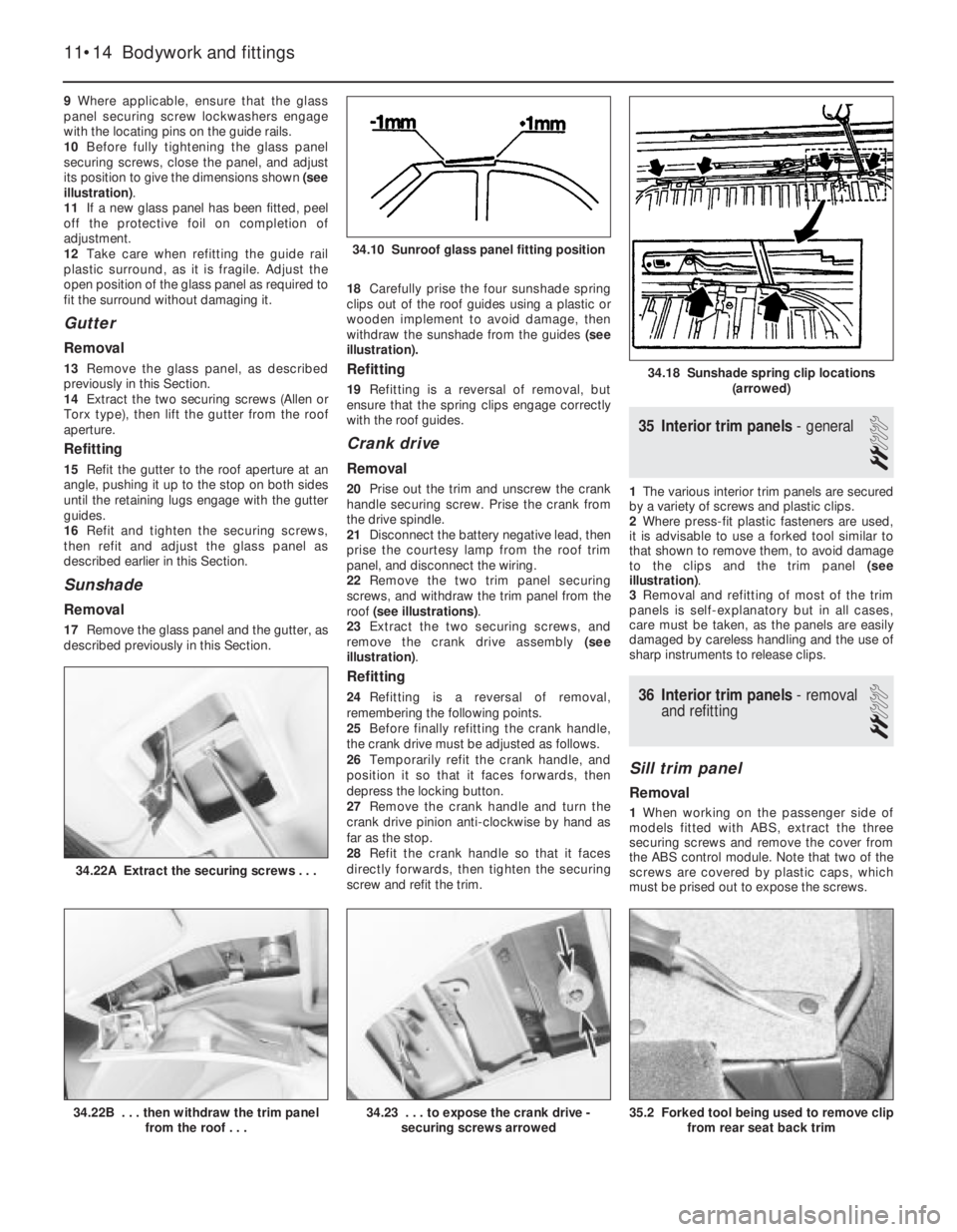
securing screws, close the panel, and adjust
its position to give the dimensions shown (see
illustration).
11If a new glass panel has been fitted, peel
off the protective foil on completion of
adjustment.
12Take care when refitting the guide rail
plastic surround, as it is fragile. Adjust the
open position of the glass panel as required to
fit the surround without damaging it.
Gutter
Removal
13Remove the glass panel, as described
previously in this Section.
14Extract the two securing screws (Allen or
Torx type), then lift the gutter from the roof
aperture.
Refitting
15Refit the gutter to the roof aperture at an
angle, pushing it up to the stop on both sides
until the retaining lugs engage with the gutter
guides.
16Refit and tighten the securing screws,
then refit and adjust the glass panel as
described earlier in this Section.
Sunshade
Removal
17Remove the glass panel and the gutter, as
described previously in this Section. 18Carefully prise the four sunshade spring
clips out of the roof guides using a plastic or
wooden implement to avoid damage, then
withdraw the sunshade from the guides (see
illustration).
Refitting
19Refitting is a reversal of removal, but
ensure that the spring clips engage correctly
with the roof guides.
Crank drive
Removal
20Prise out the trim and unscrew the crank
handle securing screw. Prise the crank from
the drive spindle.
21Disconnect the battery negative lead, then
prise the courtesy lamp from the roof trim
panel, and disconnect the wiring.
22Remove the two trim panel securing
screws, and withdraw the trim panel from the
roof (see illustrations).
23Extract the two securing screws, and
remove the crank drive assembly (see
illustration).
Refitting
24Refitting is a reversal of removal,
remembering the following points.
25Before finally refitting the crank handle,
the crank drive must be adjusted as follows.
26Temporarily refit the crank handle, and
position it so that it faces forwards, then
depress the locking button.
27Remove the crank handle and turn the
crank drive pinion anti-clockwise by hand as
far as the stop.
28Refit the crank handle so that it faces
directly forwards, then tighten the securing
screw and refit the trim.
35Interior trim panels -general
2
1The various interior trim panels are secured
by a variety of screws and plastic clips.
2Where press-fit plastic fasteners are used,
it is advisable to use a forked tool similar to
that shown to remove them, to avoid damage
to the clips and the trim panel (see
illustration).
3Removal and refitting of most of the trim
panels is self-explanatory but in all cases,
care must be taken, as the panels are easily
damaged by careless handling and the use of
sharp instruments to release clips.
36Interior trim panels -removal
and refitting
2
Sill trim panel
Removal
1When working on the passenger side of
models fitted with ABS, extract the three
securing screws and remove the cover from
the ABS control module. Note that two of the
screws are covered by plastic caps, which
must be prised out to expose the screws.
11•14Bodywork and fittings
34.22A Extract the securing screws . . .
35.2 Forked tool being used to remove clip
from rear seat back trim34.23 . . . to expose the crank drive -
securing screws arrowed34.22B . . . then withdraw the trim panel
from the roof . . .
34.18 Sunshade spring clip locations
(arrowed)
34.10 Sunroof glass panel fitting position