1988 OPEL CALIBRA washer
[x] Cancel search: washerPage 71 of 525
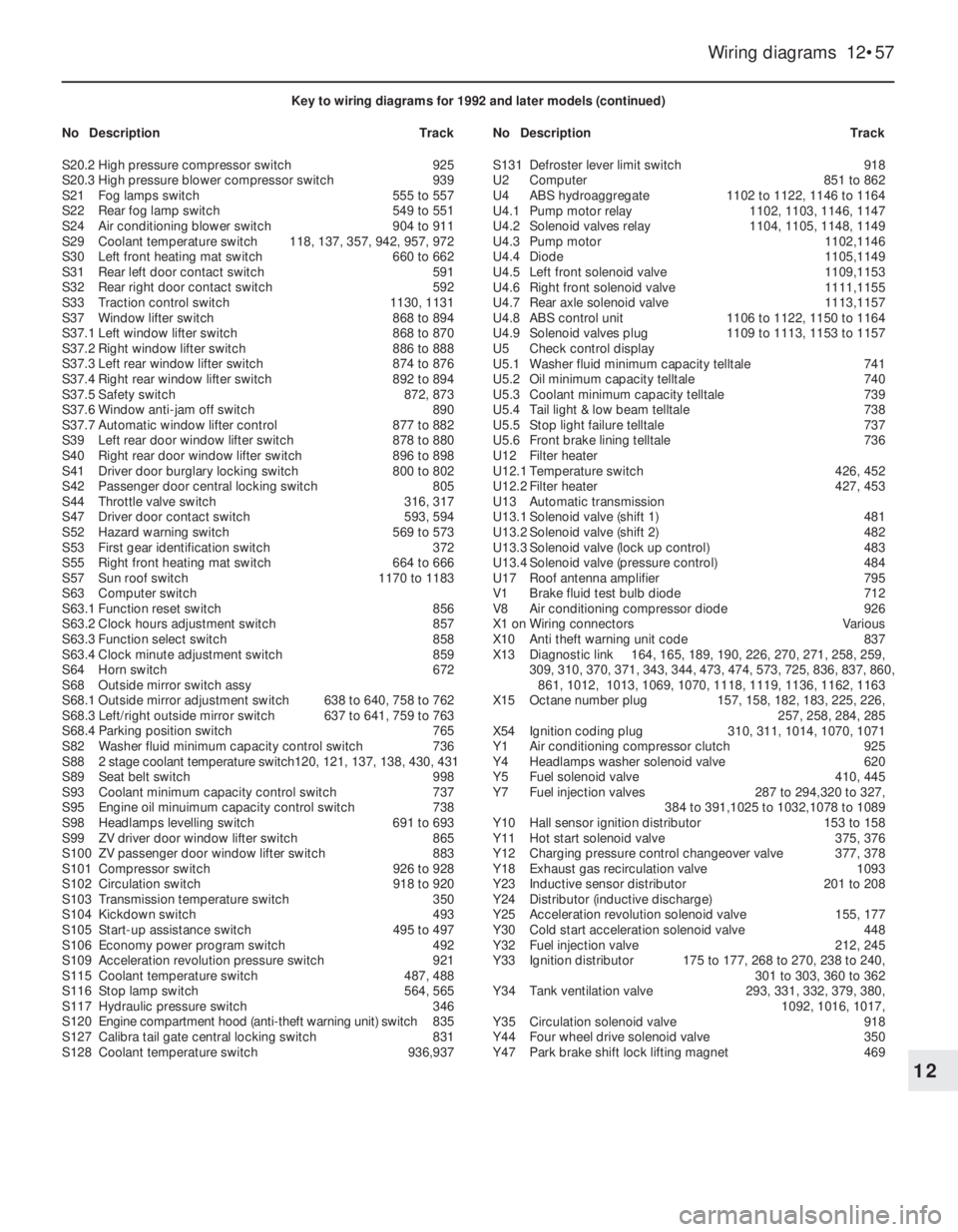
Wiring diagrams 12•57
12
Key to wiring diagrams for 1992 and later models (continued)
NoDescriptionTrackNoDescriptionTrack
S20.2High pressure compressor switch925
S20.3High pressure blower compressor switch939
S21Fog lamps switch555 to 557
S22Rear fog lamp switch549 to 551
S24Air conditioning blower switch904 to 911
S29Coolant temperature switch118, 137, 357, 942, 957, 972
S30Left front heating mat switch660 to 662
S31Rear left door contact switch591
S32Rear right door contact switch592
S33Traction control switch1130, 1131
S37Window lifter switch868 to 894
S37.1Left window lifter switch868 to 870
S37.2Right window lifter switch886 to 888
S37.3Left rear window lifter switch874 to 876
S37.4Right rear window lifter switch892 to 894
S37.5Safety switch872, 873
S37.6Window anti-jam off switch890
S37.7Automatic window lifter control877 to 882
S39Left rear door window lifter switch878 to 880
S40Right rear door window lifter switch896 to 898
S41Driver door burglary locking switch800 to 802
S42Passenger door central locking switch805
S44Throttle valve switch316, 317
S47Driver door contact switch593, 594
S52Hazard warning switch569 to 573
S53First gear identification switch372
S55Right front heating mat switch664 to 666
S57Sun roof switch1170 to 1183
S63Computer switch
S63.1Function reset switch856
S63.2Clock hours adjustment switch857
S63.3Function select switch858
S63.4Clock minute adjustment switch859
S64Horn switch672
S68Outside mirror switch assy
S68.1Outside mirror adjustment switch638 to 640, 758 to 762
S68.3Left/right outside mirror switch637 to 641, 759 to 763
S68.4Parking position switch765
S82Washer fluid minimum capacity control switch736
S882 stage coolant temperature switch120, 121, 137, 138, 430, 431
S89Seat belt switch998
S93Coolant minimum capacity control switch737
S95Engine oil minuimum capacity control switch738
S98Headlamps levelling switch691 to 693
S99ZV driver door window lifter switch865
S100ZV passenger door window lifter switch883
S101Compressor switch926 to 928
S102Circulation switch918 to 920
S103Transmission temperature switch350
S104Kickdown switch493
S105Start-up assistance switch495 to 497
S106Economy power program switch492
S109Acceleration revolution pressure switch921
S115Coolant temperature switch487, 488
S116Stop lamp switch564, 565
S117Hydraulic pressure switch346
S120Engine compartment hood (anti-theft warning unit) switch835
S127Calibra tail gate central locking switch831
S128Coolant temperature switch936,937S131Defroster lever limit switch918
U2Computer851 to 862
U4ABS hydroaggregate1102 to 1122, 1146 to 1164
U4.1Pump motor relay1102, 1103, 1146, 1147
U4.2Solenoid valves relay1104, 1105, 1148, 1149
U4.3Pump motor1102,1146
U4.4Diode1105,1149
U4.5Left front solenoid valve1109,1153
U4.6Right front solenoid valve1111,1155
U4.7Rear axle solenoid valve1113,1157
U4.8ABS control unit1106 to 1122, 1150 to 1164
U4.9Solenoid valves plug1109 to 1113, 1153 to 1157
U5Check control display
U5.1Washer fluid minimum capacity telltale741
U5.2Oil minimum capacity telltale740
U5.3Coolant minimum capacity telltale739
U5.4Tail light & low beam telltale738
U5.5Stop light failure telltale737
U5.6Front brake lining telltale736
U12Filter heater
U12.1Temperature switch426, 452
U12.2Filter heater427, 453
U13Automatic transmission
U13.1Solenoid valve (shift 1)481
U13.2Solenoid valve (shift 2)482
U13.3Solenoid valve (lock up control)483
U13.4Solenoid valve (pressure control)484
U17Roof antenna amplifier795
V1Brake fluid test bulb diode712
V8Air conditioning compressor diode926
X1 onWiring connectorsVarious
X10Anti theft warning unit code837
X13Diagnostic link164, 165, 189, 190, 226, 270, 271, 258, 259,
309, 310, 370, 371, 343, 344, 473, 474, 573, 725, 836, 837, 860,
861, 1012, 1013, 1069, 1070, 1118, 1119, 1136, 1162, 1163
X15Octane number plug157, 158, 182, 183, 225, 226,
257, 258, 284, 285
X54Ignition coding plug310, 311, 1014, 1070, 1071
Y1Air conditioning compressor clutch925
Y4Headlamps washer solenoid valve620
Y5Fuel solenoid valve410, 445
Y7Fuel injection valves287 to 294,320 to 327,
384 to 391,1025 to 1032,1078 to 1089
Y10Hall sensor ignition distributor153 to 158
Y11Hot start solenoid valve375, 376
Y12Charging pressure control changeover valve377, 378
Y18Exhaust gas recirculation valve1093
Y23Inductive sensor distributor201 to 208
Y24Distributor (inductive discharge)
Y25Acceleration revolution solenoid valve155, 177
Y30Cold start acceleration solenoid valve 448
Y32Fuel injection valve212, 245
Y33Ignition distributor175 to 177, 268 to 270, 238 to 240,
301 to 303, 360 to 362
Y34Tank ventilation valve293, 331, 332, 379, 380,
1092, 1016, 1017,
Y35Circulation solenoid valve918
Y44Four wheel drive solenoid valve350
Y47Park brake shift lock lifting magnet469
Page 94 of 525

9Alternator-removal and
refitting
3
Note: Refer to Section 3 before proceeding
Except ‘compact’ series
alternators
Removal
1Disconnect the battery leads.
2Disconnect the air trunking from the air
cleaner, and the air box or throttle body, as
applicable, and remove it for improved
access.
3Disconnect the wiring plug, or disconnect
the wires from their terminals on the rear of
the alternator, noting their locations (see
illustration).
4Remove the drivebelt, (Section 8).
5Unscrew the two mounting bolts and nuts
and recover any washers and insulating
bushes, noting their locations. Note the earth
strap attached to the top mounting bolt (see
illustration).
6Withdraw the alternator, taking care not to
knock or drop it, as this can cause irreparable
damage.
Refitting
7Refitting is a reversal of removal,
remembering the following points.
8Ensure that the earth lead is in place on the
top mounting bolt.
9Refit and tension the drivebelt, (Section 8).
‘Compact’ series alternators
Removal
10Disconnect the battery negative lead.
11Remove the air inlet trunking and, if
necessary for improved access, the air
cleaner assembly.
12Mark the rotational direction on the
alternator drivebelt with chalk.
13Using a spanner or socket on the
automatic tensioning roller hexagon turn the
tensioning roller clockwise (as viewed from
the right-hand side of the car) and hold it in
this position. With the drivebelt tension
released, slip the drivebelt off the alternator
pulley, then allow the tensioner to return to its
original position.14Disconnect the electrical cable
connections at the rear of the alternator.
15Undo and remove the alternator lower
mounting bolt, and slacken both upper bolts
that secure the alternator mounting brackets
to the engine.
16Undo and remove both bolts that secure
the alternator to its mounting brackets, noting
the location of the different length bolts.
Swing the brackets clear and remove the
alternator from the engine.
Refitting
17Refitting is a reversal of removal. Tighten
the mounting bolts to the specified torque,
and refit the drivebelt as described in
Section 8.
10Alternator -testing
5
Due to the specialist knowledge and
equipment required to test or service an
alternator, it is recommended that if a fault is
suspected, the vehicle is taken to a dealer or a
specialist. Information is limited to the
inspection and renewal of the brushes.
Should the alternator not charge, or the
system be suspect, the following points may
be checked before seeking further assistance:
a)Check the drivebelt tension, as described
in Section 8
b)Check the condition of the battery and its
connections -see Section 5c)Inspect all electrical cables and
connections for condition and security
Note that if the alternator is found to be
faulty, it may prove more economical to buy a
factory-reconditioned unit, rather than having
the existing unit overhauled.
11Alternator brushes -removal,
inspection and refitting
3
Removal
Delco-Remy type (except ‘compact’
series)
1Remove the alternator, as described in
Section 9
2Scribe a line across the drive end housing
and the slip ring end housing, to ensure
correct alignment when reassembling.
3Unscrew the three through-bolts, and prise
the drive end housing and rotor away from the
slip ring end housing and stator (see
illustration).
4Check the condition of the slip rings, and if
necessary clean with a rag or very fine glass
paper (see illustration).
5Remove the three nuts and washers
securing the stator leads to the rectifier, and
lift away the stator assembly (see
illustration).
Engine electrical systems 5•7
11.3 Separating the drive end housing
from the slip ring end housing - Delco-
Remy alternator
11.4 Alternator slip rings (arrowed) -
Delco-Remy alternator
11.5 Delco-Remy alternator
A Stator lead securing nuts
B Brush holder/voltage regulator
securing screws
9.5 Disconnecting the earth lead from the
top alternator mounting bolt9.3 Disconnecting the wires from the
terminals on the rear of the alternator -
Delco-Remy alternator
5
Page 95 of 525
6Remove the terminal screw and lift out the
diode assembly.
7Extract the two screws securing the brush
holder and voltage regulator to the slip ring
end housing, and remove the brush holder
assembly. Note the insulation washers under
the screw heads.
8Check that the brushes move freely in their
guides, and that the brush lengths are within
the limits given in the Specifications. If any
doubt exists regarding the condition of the
brushes, the best policy is to renew them.
9To fit new brushes, unsolder the old brush
leads from the brush holder, and solder on the
new leads in exactly the same place.
10Check that the new brushes move freely
in the guides.
Refitting
11Before refitting the brush holder
assembly, retain the brushes in the retracted
position using a stiff piece of wire or a twist
drill.
12Refit the brush holder assembly so that
the wire or drill protrudes through the slot in
the slip ring end housing, and tighten the
securing screws.
13Refit the diode assembly and the stator
assembly to the housing, ensuring that the
stator leads are in their correct positions, and
refit the terminal screw and nuts.
14Assemble the drive end housing and rotor
to the slip ring end housing, ensuring that the
previously made marks are aligned. Insert and
tighten the three through-bolts.
15Pull the wire or drill, as applicable, from
the slot in the slip ring end housing so that the
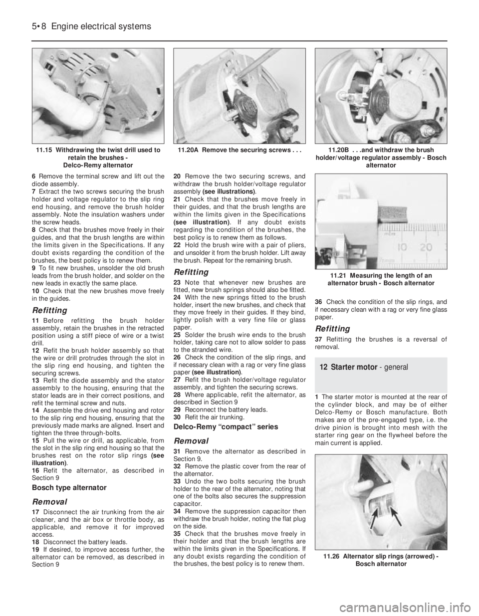
brushes rest on the rotor slip rings (see
illustration).
16Refit the alternator, as described in
Section 9
Bosch type alternator
Removal
17Disconnect the air trunking from the air
cleaner, and the air box or throttle body, as
applicable, and remove it for improved
access.
18Disconnect the battery leads.
19If desired, to improve access further, the
alternator can be removed, as described in
Section 920Remove the two securing screws, and
withdraw the brush holder/voltage regulator
assembly (see illustrations).
21Check that the brushes move freely in
their guides, and that the brush lengths are
within the limits given in the Specifications
(see illustration). If any doubt exists
regarding the condition of the brushes, the
best policy is to renew them as follows.
22Hold the brush wire with a pair of pliers,
and unsolder it from the brush holder. Lift away
the brush. Repeat for the remaining brush.
Refitting
23Note that whenever new brushes are
fitted, new brush springs should also be fitted.
24With the new springs fitted to the brush
holder, insert the new brushes, and check that
they move freely in their guides. If they bind,
lightly polish with a very fine file or glass
paper.
25Solder the brush wire ends to the brush
holder, taking care not to allow solder to pass
to the stranded wire.
26Check the condition of the slip rings, and
if necessary clean with a rag or very fine glass
paper (see illustration).
27Refit the brush holder/voltage regulator
assembly, and tighten the securing screws.
28Where applicable, refit the alternator, as
described in Section 9
29Reconnect the battery leads.
30Refit the air trunking.
Delco-Remy “compact” series
Removal
31Remove the alternator as described in
Section 9.
32Remove the plastic cover from the rear of
the alternator.
33Undo the two bolts securing the brush
holder to the rear of the alternator, noting that
one of the bolts also secures the suppression
capacitor.
34Remove the suppression capacitor then
withdraw the brush holder, noting the flat plug
on the side.
35Check that the brushes move freely in
their holder and that the brush lengths are
within the limits given in the Specifications. If
any doubt exists regarding the condition of
the brushes, the best policy is to renew them.36Check the condition of the slip rings, and
if necessary clean with a rag or very fine glass
paper.
Refitting
37Refitting the brushes is a reversal of
removal.
12Starter motor - general
1The starter motor is mounted at the rear of
the cylinder block, and may be of either
Delco-Remy or Bosch manufacture. Both
makes are of the pre-engaged type, i.e. the
drive pinion is brought into mesh with the
starter ring gear on the flywheel before the
main current is applied.
5•8Engine electrical systems
11.15 Withdrawing the twist drill used to
retain the brushes -
Delco-Remy alternator11.20B . . .and withdraw the brush
holder/voltage regulator assembly - Bosch
alternator
11.26 Alternator slip rings (arrowed) -
Bosch alternator
11.21 Measuring the length of an
alternator brush - Bosch alternator
11.20A Remove the securing screws . . .
Page 99 of 525
been removed, check that No 1 cylinder is on
its firing stroke by removing No 1 cylinder
spark plug and placing a finger over the plug
hole. Turn the crankshaft until compression
can be felt, which indicates that No 1 piston is
rising on its compression stroke. Continue
turning the crankshaft until the relevant timing
marks are in alignment.
11Turn the rotor arm to the position noted in
paragraph 6c, and hold the rotor arm in this
position as the distributor is fitted. Note that
the distributor driveshaft will only engage with
the camshaft in one position. If the original
distributor is being refitted, align the marks
made on the distributor body and camshaft
housing before removal.
12Refit the clamp plate and nut, but do not
fully tighten the nut at this stage.
13On the Bosch distributor, remove the rotor
arm, then refit the plastic shield and the rotor
arm.
14On 14 NV models, reconnect the vacuum
pipe to the diaphragm unit.
15Reconnect the distributor wiring plug.
16Refit the distributor cap as described in
Section 17.
17Reconnect the battery negative lead.
18Check and if necessary adjust the ignition
timing, as described in Section 21.
19Distributor (DOHC models),
where applicable - removal
and refitting
3
Removal
1Disconnect the battery negative lead.
2Remove the distributor cap, as described in
Section 17.
3Disconnect the distributor wiring plug.
4Unscrew the two securing bolts, and
remove the distributor from the cylinder head.
5Examine the O-ring on the rear of the
distributor, and renew if necessary.
Refitting
6Refitting is a reversal of removal. However,
note that the distributor should be fitted so
that the wiring plug is positioned on the upper
left-hand side of the distributor body, when
viewed from the distributor cap end.
20Distributor - dismantling,
inspection and reassembly
3
Note: Before contemplating dismantling of a
distributor, check the cost and availability of
replacement parts. It may prove more
economical to renew the complete distributor
assembly
14 NV models
Dismantling
1With the distributor removed as described
in Section 18, continue as follows.
2Pull off the rotor arm, and remove the
plastic shield.
3The top bearing plate can be removed after
unscrewing the two securing screws, however
(other than the vacuum diaphragm unit), no
spares are available for the distributor and no
adjustments are required.
4If desired, the vacuum diaphragm unit can
be removed by extracting the two securing
screws and unhooking the operating arm from
the distributor baseplate. Note that the
screws are of differing lengths, the longer
screw also secures one of the distributor cap
clips.
Inspection
5The vacuum unit can be tested by applying
suction to the vacuum port, and checking that
the operating rod moves into the unit as
suction is applied. Remove the suction, and
check that the operating rod returns to its
original position. If the operating rod does not
move as described, renew the vacuum unit.
6Check the distributor cap for corrosion of
the segments, and for signs of tracking,
indicated by a thin black line between the
segments. Make sure that the carbon brush in
the centre of the cap moves freely and stands
proud of the surface of the cap. Renew the
cap if necessary.
7If the metal portion of the rotor arm is badly
burnt or loose, renew it. If slightly burnt or
corroded; it may be cleaned with a fine file.
8Examine the seal ring at the rear of the
distributor body, and renew if necessary.
Reassembly
9Reassembly is a reversal of dismantling,
ensuring that the vacuum unit operating arm
is correctly engaged with the peg on the
baseplate, several attempts may be required
to reconnect it.
10Refit the distributor as described in
Section 18, and then check and if necessary
adjust the ignition timing, as described in
Section 21.
16 SV models
Dismantling
11With the distributor removed as described
in Section 18, pull off the rotor arm and, on
the Bosch distributor, remove the plastic
shield.
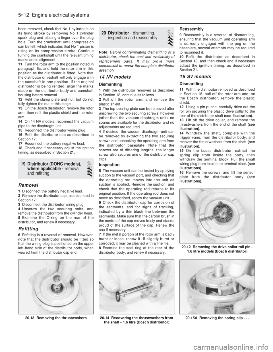
12Using a pin punch, carefully drive out the
roll pin securing the plastic drive collar to the
rear of the distributor shaft (see illustration).
13Lift off the drive collar, and remove the
thrustwashers from the end of the shaft (see
illustration).
14Withdraw the shaft, complete with the
trigger vane, from the distributor body, and
recover the thrustwashers from the shaft (see
illustration).
15On the Lucas distributor, extract the
spring clip from inside the body, then
withdraw the terminal block. Pull the small
wiring plug from inside the terminal block (see
illustrations).
16Remove the screws, and lift the sensor
plate from the distributor body (see
illustrations).
5•12Engine electrical systems
20.15A Removing the spring clip . . .20.14 Recovering the thrustwashers from
the shaft - 1.6 litre (Bosch distributor)20.13 Removing the thrustwashers
20.12 Removing the drive collar roll pin -
1.6 litre models (Bosch distributor)
Page 100 of 525
Inspection
17Examine the distributor cap and rotor arm,
as described in paragraphs 6 and 7. Examine
the O-rings at the rear of the distributor body,
and on the rear of the shaft, and renew if
necessary.
Reassembly
18Reassembly is a reversal of dismantling,
ensuring that the thrustwashers are correctly
located. Note that the drive collar should be
refitted so that the drive peg on the collar is
aligned with the groove in the top of the
distributor shaft (it is possible to fit the drive
collar 180°out of position).
19Refit the distributor as described in
Section 18, and then check and if necessary
adjust the ignition timing, as described in
Section 21.
DOHC models (where
applicable)
20The distributor cap and rotor arm can be
examined as described in paragraphs 6 and 7.
21Ignition timing -checking and
adjustment
4
Note: Refer to Section 3 before proceeding. A
tachometer and a timing light will be required
during this procedure. For details of ignition
timing adjustment required to operate vehicles
on unleaded petrol, refer to Section 22.
14 NV and 16 SV models
Checking
1Start the engine and run it until it reaches
normal operating temperature, then switch
off.
2On 14 NV models, disconnect the vacuum
pipe from the distributor vacuum diaphragm
unit.
3On all models use a spanner applied to the
crankshaft pulley bolt to rotate the crankshaft
clockwise until the notch in the pulley’s
inboard rim aligns with the pointer protruding
from the oil pump housing. On 14 NV models,
where two notches (indicating 10°and 5°
BTDC respectively) are found, rotate the
crankshaft until the second notch (in thedirection of rotation -i.e. 5°BTDC) aligns. Use
white paint or similar to emphasise the pointer
and notch, to make them easier to see.
4Connect a timing light to No 1 cylinder
(nearest the timing belt end of the engine) HT
lead, also a tachometer; follow the equipment
manufacturer’s instructions for connection.
5Start the engine and allow it to idle -the
speed should be between 700 and 1000 rpm.
6On 14 NV models, aim the timing light at the
pointer and check that it is aligned with the
crankshaft pulley notch.
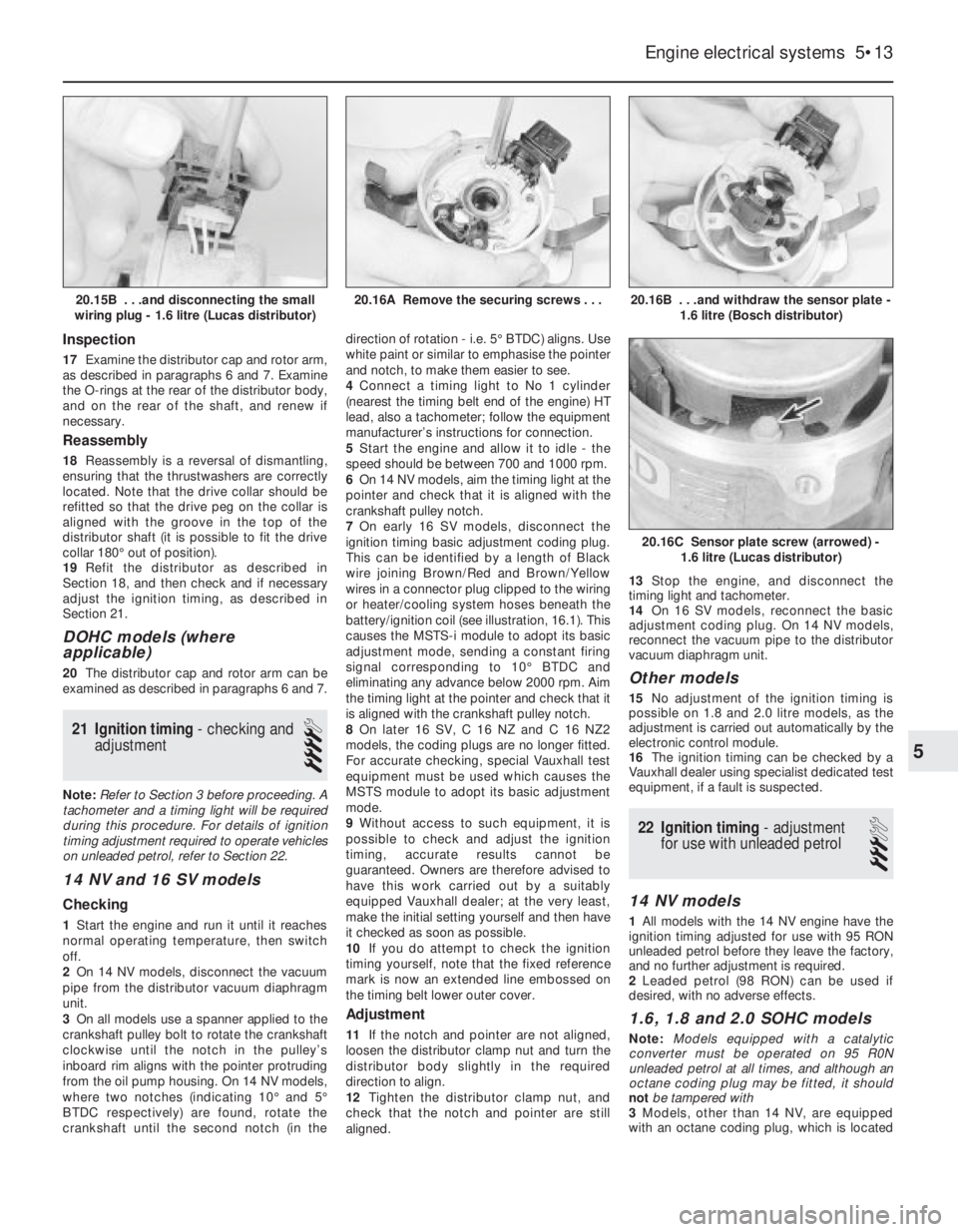
7On early 16 SV models, disconnect the
ignition timing basic adjustment coding plug.
This can be identified by a length of Black
wire joining Brown/Red and Brown/Yellow
wires in a connector plug clipped to the wiring
or heater/cooling system hoses beneath the
battery/ignition coil (see illustration, 16.1). This
causes the MSTS-i module to adopt its basic
adjustment mode, sending a constant firing
signal corresponding to 10°BTDC and
eliminating any advance below 2000 rpm. Aim
the timing light at the pointer and check that it
is aligned with the crankshaft pulley notch.
8On later 16 SV, C 16 NZ and C 16 NZ2
models, the coding plugs are no longer fitted.
For accurate checking, special Vauxhall test
equipment must be used which causes the
MSTS module to adopt its basic adjustment
mode.
9Without access to such equipment, it is
possible to check and adjust the ignition
timing, accurate results cannot be
guaranteed. Owners are therefore advised to
have this work carried out by a suitably
equipped Vauxhall dealer; at the very least,
make the initial setting yourself and then have
it checked as soon as possible.
10If you do attempt to check the ignition
timing yourself, note that the fixed reference
mark is now an extended line embossed on
the timing belt lower outer cover.
Adjustment
11If the notch and pointer are not aligned,
loosen the distributor clamp nut and turn the
distributor body slightly in the required
direction to align.
12Tighten the distributor clamp nut, and
check that the notch and pointer are still
aligned. 13Stop the engine, and disconnect the
timing light and tachometer.
14On 16 SV models, reconnect the basic
adjustment coding plug. On 14 NV models,
reconnect the vacuum pipe to the distributor
vacuum diaphragm unit.
Other models
15No adjustment of the ignition timing is
possible on 1.8 and 2.0 litre models, as the
adjustment is carried out automatically by the
electronic control module.
16The ignition timing can be checked by a
Vauxhall dealer using specialist dedicated test
equipment, if a fault is suspected.
22Ignition timing -adjustment
for use with unleaded petrol
3
14 NV models
1All models with the 14 NV engine have the
ignition timing adjusted for use with 95 RON
unleaded petrol before they leave the factory,
and no further adjustment is required.
2Leaded petrol (98 RON) can be used if
desired, with no adverse effects.
1.6, 1.8 and 2.0 SOHC models
Note: Models equipped with a catalytic
converter must be operated on 95 R0N
unleaded petrol at all times, and although an
octane coding plug may be fitted, it should
not be tampered with
3Models, other than 14 NV, are equipped
with an octane coding plug, which is located
Engine electrical systems 5•13
20.16B . . .and withdraw the sensor plate -
1.6 litre (Bosch distributor)
20.16C Sensor plate screw (arrowed) -
1.6 litre (Lucas distributor)
20.16A Remove the securing screws . . .20.15B . . .and disconnecting the small
wiring plug - 1.6 litre (Lucas distributor)
5
Page 107 of 525
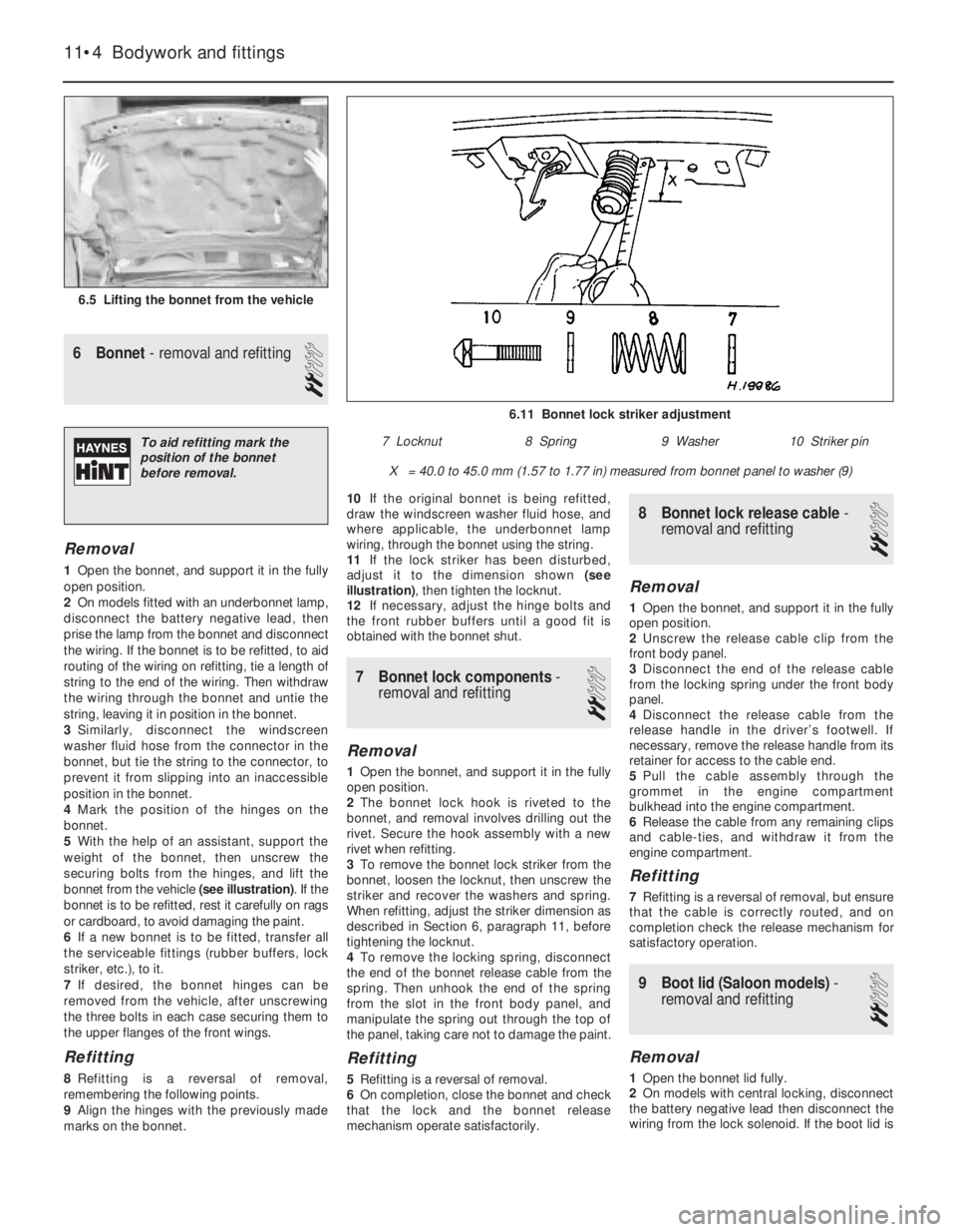
6Bonnet - removal and refitting
2
Removal
1Open the bonnet, and support it in the fully
open position.
2On models fitted with an underbonnet lamp,
disconnect the battery negative lead, then
prise the lamp from the bonnet and disconnect
the wiring. If the bonnet is to be refitted, to aid
routing of the wiring on refitting, tie a length of
string to the end of the wiring. Then withdraw
the wiring through the bonnet and untie the
string, leaving it in position in the bonnet.
3Similarly, disconnect the windscreen
washer fluid hose from the connector in the
bonnet, but tie the string to the connector, to
prevent it from slipping into an inaccessible
position in the bonnet.
4Mark the position of the hinges on the
bonnet.
5With the help of an assistant, support the
weight of the bonnet, then unscrew the
securing bolts from the hinges, and lift the
bonnet from the vehicle (see illustration). If the
bonnet is to be refitted, rest it carefully on rags
or cardboard, to avoid damaging the paint.
6If a new bonnet is to be fitted, transfer all
the serviceable fittings (rubber buffers, lock
striker, etc.), to it.
7If desired, the bonnet hinges can be
removed from the vehicle, after unscrewing
the three bolts in each case securing them to
the upper flanges of the front wings.
Refitting
8Refitting is a reversal of removal,
remembering the following points.
9Align the hinges with the previously made
marks on the bonnet.10If the original bonnet is being refitted,
draw the windscreen washer fluid hose, and
where applicable, the underbonnet lamp
wiring, through the bonnet using the string.
11If the lock striker has been disturbed,
adjust it to the dimension shown (see
illustration), then tighten the locknut.
12If necessary, adjust the hinge bolts and
the front rubber buffers until a good fit is
obtained with the bonnet shut.
7Bonnet lock components -
removal and refitting
2
Removal
1Open the bonnet, and support it in the fully
open position.
2The bonnet lock hook is riveted to the
bonnet, and removal involves drilling out the
rivet. Secure the hook assembly with a new
rivet when refitting.
3To remove the bonnet lock striker from the
bonnet, loosen the locknut, then unscrew the
striker and recover the washers and spring.
When refitting, adjust the striker dimension as
described in Section 6, paragraph 11, before
tightening the locknut.
4To remove the locking spring, disconnect
the end of the bonnet release cable from the
spring. Then unhook the end of the spring
from the slot in the front body panel, and
manipulate the spring out through the top of
the panel, taking care not to damage the paint.
Refitting
5Refitting is a reversal of removal.
6On completion, close the bonnet and check
that the lock and the bonnet release
mechanism operate satisfactorily.
8Bonnet lock release cable -
removal and refitting
2
Removal
1Open the bonnet, and support it in the fully
open position.
2Unscrew the release cable clip from the
front body panel.
3Disconnect the end of the release cable
from the locking spring under the front body
panel.
4Disconnect the release cable from the
release handle in the driver’s footwell. If
necessary, remove the release handle from its
retainer for access to the cable end.
5Pull the cable assembly through the
grommet in the engine compartment
bulkhead into the engine compartment.
6Release the cable from any remaining clips
and cable-ties, and withdraw it from the
engine compartment.
Refitting
7Refitting is a reversal of removal, but ensure
that the cable is correctly routed, and on
completion check the release mechanism for
satisfactory operation.
9Boot lid (Saloon models) -
removal and refitting
2
Removal
1Open the bonnet lid fully.
2On models with central locking, disconnect
the battery negative lead then disconnect the
wiring from the lock solenoid. If the boot lid is
11•4Bodywork and fittings
6.5 Lifting the bonnet from the vehicle
6.11 Bonnet lock striker adjustment
X = 40.0 to 45.0 mm (1.57 to 1.77 in) measured from bonnet panel to washer (9)
7 Locknut8 Spring9 Washer10 Striker pinTo aid refitting mark the
position of the bonnet
before removal.
Page 108 of 525
to be refitted, tie a length of string to the end
of the wiring. Then feed the wiring through the
boot lid and untie the string, leaving it in
position in the boot lid to assist refitting.
3Mark the position of the hinges on the boot
lid.
4With the help of an assistant, support the
weight of the boot lid, then unscrew the
securing bolts from the hinges, and lift the
boot lid from the vehicle. If the boot lid is to be
refitted, rest it carefully on rags or cardboard,
to avoid damaging the paint.
5If a new boot lid is to be fitted, transfer all
the serviceable fittings (rubber buffers, lock
mechanism, etc.), to it.
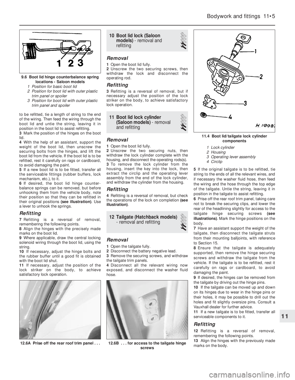
6If desired, the boot lid hinge counter-
balance springs can be removed, but before
unhooking them from the vehicle body, note
their position so that they can be refitted in
their original positions (see illustration). Use
a lever to unhook the springs.
Refitting
7Refitting is a reversal of removal,
remembering the following points.
8Align the hinges with the precisely made
marks on the boot lid.
9Where applicable, draw the central locking
solenoid wiring through the boot lid, using the
string.
10If necessary, adjust the hinge bolts and
the rubber buffer until a good fit is obtained
with the boot lid shut.
11If necessary, adjust the position of the
lock striker on the body, to achieve
satisfactory lock operation.
10Boot lid lock (Saloon
models) - removal and
refitting
2
Removal
1Open the boot lid fully.
2Unscrew the two securing screws, then
withdraw the lock and disconnect the
operating rod.
Refitting
3Refitting is a reversal of removal, but if
necessary adjust the position of the lock
striker on the body, to achieve satisfactory
lock operation.
11Boot lid lock cylinder
(Saloon models) - removal
and refitting
2
Removal
1Open the boot lid fully.
2Unscrew the two securing nuts, then
withdraw the lock cylinder complete with the
housing, and disconnect the operating rods(s).
3To remove the lock cylinder from the
housing, insert the key into the lock, then
extract the circlip and the operating lever
assembly from the end of the lock cylinder,
and withdraw the cylinder from the housing.
Refitting
4Refitting is a reversal of removal, but check
the operations of the lock on completion (see
illustration).
12Tailgate (Hatchback models)
-removal and refitting
2
Removal
1Open the tailgate fully.
2Disconnect the battery negative lead.
3Remove the securing screws, and withdraw
the tailgate trim panels.
4Disconnect all the relevant wiring now
exposed, and disconnect the washer fluid
hose.5If the original tailgate is to be refitted, tie
string to the ends of all the relevant wires, and
if necessary the washer fluid hose, then feed
the wiring and the hose through the top edge
of the tailgate. Untie the string, leaving it in
position in the tailgate to assist refitting.
6Prise off the rear roof trim panel, taking care
not to break the securing clips, and lower the
rear of the headlining slightly for access to the
tailgate hinge securing screws (see
illustrations). Mark the hinge positions on the
body.
7Have an assistant support the weight of the
tailgate, then disconnect the tailgate struts
from their mounting balljoints, with reference
to Section 15.
8Ensure that the tailgate is adequately
supported, then remove the hinge securing
screws and withdraw the tailgate from the
vehicle. If the tailgate is to be refitted, rest it
carefully on rags or cardboard, to avoid
damaging the paint.
9If desired, the hinges can be removed from
the tailgate by driving out the hinge pins.
10If the tailgate can be moved up and down
on its hinges due to wear in the hinge pins or
their holes, it may be possible to drill out the
holes and fit slightly oversize pins. Consult a
Vauxhall dealer for further advice.
11If a new tailgate is to be fitted, transfer all
serviceable components to it.
Refitting
12Refitting is a reversal of removal,
remembering the following points.
13Align the hinges with the previously made
marks on the body.
Bodywork and fittings 11•5
12.6B . . . for access to the tailgate hinge
screws12.6A Prise off the rear roof trim panel . . .
11.4 Boot lid/tailgate lock cylinder
components
1 Lock cylinder
2 Housing
3 Operating lever assembly
4 Circlip
9.6 Boot lid hinge counterbalance spring
locations - Saloon models
1 Position for basic boot lid
2 Position for boot lid with outer plastic
trim panel or spoiler
3 Position for boot lid with outer plastic
trim panel and spoiler
11
Page 109 of 525
14If the original tailgate is being refitted,
draw the wiring and washer fluid hose (where
applicable) through the tailgate, using the
string.
15If necessary, adjust the hinge bolts and
the rubber buffers, to obtain a good fit when
the tailgate is shut.
16If necessary, adjust the position of the
lock striker on the body, to achieve
satisfactory lock operation.
13Tailgate lock (Hatchback
models) - removal and
refitting
2
Proceed as described in Section 10, but
note that for access to the lock, the rear
tailgate trim panel must be removed, after
unscrewing the securing screws. Note also
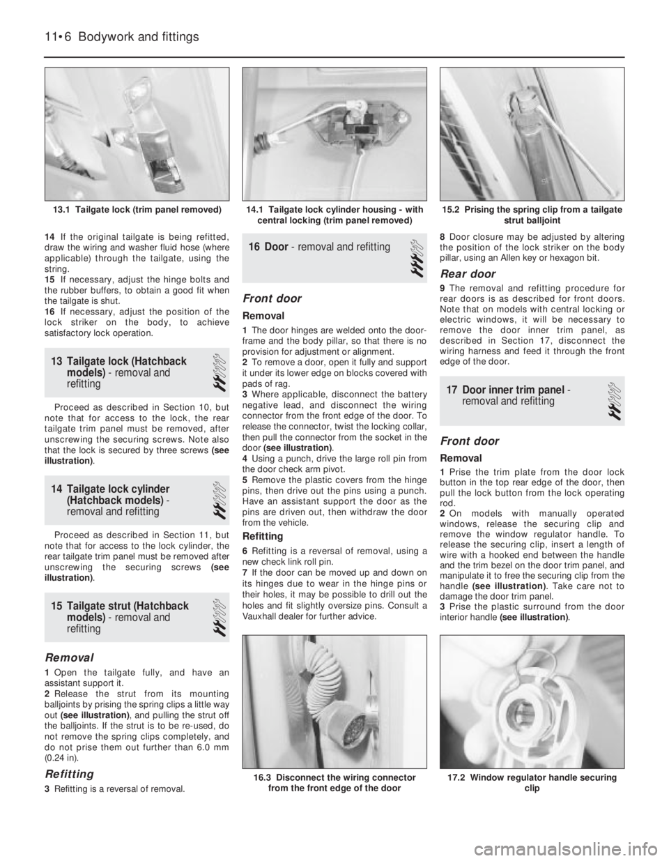
that the lock is secured by three screws (see
illustration).
14Tailgate lock cylinder
(Hatchback models) -
removal and refitting
2
Proceed as described in Section 11, but
note that for access to the lock cylinder, the
rear tailgate trim panel must be removed after
unscrewing the securing screws (see
illustration).
15Tailgate strut (Hatchback
models) - removal and
refitting
2
Removal
1Open the tailgate fully, and have an
assistant support it.
2Release the strut from its mounting
balljoints by prising the spring clips a little way
out (see illustration), and pulling the strut off
the balljoints. If the strut is to be re-used, do
not remove the spring clips completely, and
do not prise them out further than 6.0 mm
(0.24 in).
Refitting
3Refitting is a reversal of removal.
16Door - removal and refitting
3
Front door
Removal
1The door hinges are welded onto the door-
frame and the body pillar, so that there is no
provision for adjustment or alignment.
2To remove a door, open it fully and support
it under its lower edge on blocks covered with
pads of rag.
3Where applicable, disconnect the battery
negative lead, and disconnect the wiring
connector from the front edge of the door. To
release the connector, twist the locking collar,
then pull the connector from the socket in the
door (see illustration).
4Using a punch, drive the large roll pin from
the door check arm pivot.
5Remove the plastic covers from the hinge
pins, then drive out the pins using a punch.
Have an assistant support the door as the
pins are driven out, then withdraw the door
from the vehicle.
Refitting
6Refitting is a reversal of removal, using a
new check link roll pin.
7If the door can be moved up and down on
its hinges due to wear in the hinge pins or
their holes, it may be possible to drill out the
holes and fit slightly oversize pins. Consult a
Vauxhall dealer for further advice.8Door closure may be adjusted by altering
the position of the lock striker on the body
pillar, using an Allen key or hexagon bit.
Rear door
9The removal and refitting procedure for
rear doors is as described for front doors.
Note that on models with central locking or
electric windows, it will be necessary to
remove the door inner trim panel, as
described in Section 17, disconnect the
wiring harness and feed it through the front
edge of the door.
17Door inner trim panel -
removal and refitting
2
Front door
Removal
1Prise the trim plate from the door lock
button in the top rear edge of the door, then
pull the lock button from the lock operating
rod.
2On models with manually operated
windows, release the securing clip and
remove the window regulator handle. To
release the securing clip, insert a length of
wire with a hooked end between the handle
and the trim bezel on the door trim panel, and
manipulate it to free the securing clip from the
handle (see illustration). Take care not to
damage the door trim panel.
3Prise the plastic surround from the door
interior handle (see illustration).
11•6Bodywork and fittings
15.2 Prising the spring clip from a tailgate
strut balljoint
17.2 Window regulator handle securing
clip16.3 Disconnect the wiring connector
from the front edge of the door
14.1 Tailgate lock cylinder housing - with
central locking (trim panel removed)13.1 Tailgate lock (trim panel removed)