1988 OPEL CALIBRA tow
[x] Cancel search: towPage 11 of 525
5Remove the three screws securing the
choke assembly to the carburettor body.
Allow the choke assembly to drop down, but
do not disconnect the choke linkage.
6Remove the star clip that secures the
diaphragm unit to the carburettor top cover,
and withdraw the diaphragm unit.
Refitting
7Refitting is a reversal of removal, but use a
new star clip to secure the diaphragm unit to
the carburettor top cover. Before refitting the
air box to the top of the carburettor, check
and if necessary adjust the choke pull-down,
as follows.
Vacuum pull-down
Adjustment
8With the air cleaner or air box removed from
the top of the carburettor, as described in
Section 17, paragraph 2, continue as follows.
9Note the position of the bi-metal housing
alignment marks as an aid to refitting, if
necessary making additional marks for clarity,
then remove the three securing screws, and
lift off the bi-metal housing. Place the housing
to one side, taking care not to strain the
coolant hoses or electric choke heater wiring.
10Position the fast idle speed adjustment
screw on the highest step of the fast idle cam,
and check that the choke valve is closed.
11Move the pull-down arm towards the
diaphragm unit by pushing on the adjustment
screw until resistance is felt. Hold the arm in
this position.
12Using a drill shank of appropriate
diameter, or a similar item, measure the
clearance between the lower side of the
choke plate and the wall of the primary barrel
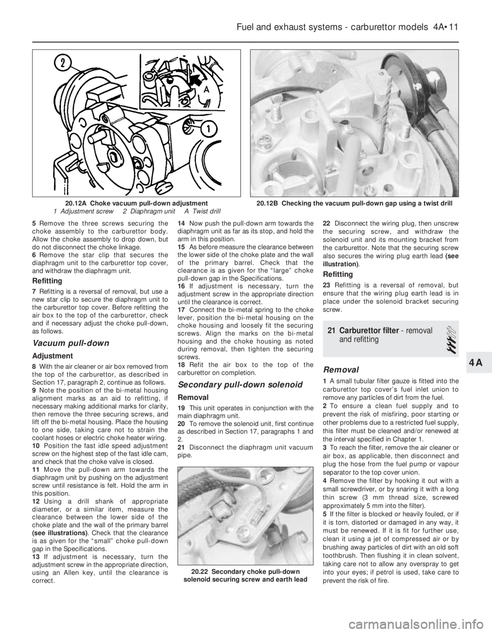
(see illustrations). Check that the clearance
is as given for the “small” choke pull-down
gap in the Specifications.
13If adjustment is necessary, turn the
adjustment screw in the appropriate direction,
using an Allen key, until the clearance is
correct.14Now push the pull-down arm towards the
diaphragm unit as far as its stop, and hold the
arm in this position.
15As before measure the clearance between
the lower side of the choke plate and the wall
of the primary barrel. Check that the
clearance is as given for the “large” choke
pull-down gap in the Specifications.
16If adjustment is necessary, turn the
adjustment screw in the appropriate direction
until the clearance is correct.
17Connect the bi-metal spring to the choke
lever, position the bi-metal housing on the
choke housing and loosely fit the securing
screws. Align the marks on the bi-metal
housing and the choke housing as noted
during removal, then tighten the securing
screws.
18Refit the air box to the top of the
carburettor on completion.
Secondary pull-down solenoid
Removal
19This unit operates in conjunction with the
main diaphragm unit.
20To remove the solenoid unit, first continue
as described in Section 17, paragraphs 1 and
2.
21Disconnect the diaphragm unit vacuum
pipe.22Disconnect the wiring plug, then unscrew
the securing screw, and withdraw the
solenoid unit and its mounting bracket from
the carburettor. Note that the securing screw
also secures the wiring plug earth lead (see
illustration).
Refitting
23Refitting is a reversal of removal, but
ensure that the wiring plug earth lead is in
place under the solenoid bracket securing
screw.
21Carburettor filter -removal
and refitting
3
Removal
1A small tubular filter gauze is fitted into the
carburettor top cover’s fuel inlet union to
remove any particles of dirt from the fuel.
2To ensure a clean fuel supply and to
prevent the risk of misfiring, poor starting or
other problems due to a restricted fuel supply,
this filter must be cleaned and/or renewed at
the interval specified in Chapter 1.
3To reach the filter, remove the air cleaner or
air box, as applicable, then disconnect and
plug the hose from the fuel pump or vapour
separator to the top cover union.
4Remove the filter by hooking it out with a
small screwdriver, or by snaring it with a long
thin screw (3 mm thread size, screwed
approximately 5 mm into the filter).
5If the filter is blocked or heavily fouled, or if
it is torn, distorted or damaged in any way, it
must be renewed. If it is fit for further use,
clean it using a jet of compressed air or by
brushing away particles of dirt with an old soft
toothbrush. Then flushing it in clean solvent,
taking care not to allow any overspray to get
into your eyes; if petrol is used, take care to
prevent the risk of fire.
Fuel and exhaust systems - carburettor models 4A•11
20.12B Checking the vacuum pull-down gap using a twist drill
20.22 Secondary choke pull-down
solenoid securing screw and earth lead
20.12A Choke vacuum pull-down adjustment
1 Adjustment screw 2 Diaphragm unit A Twist drill
4A
Page 18 of 525
5Direction indicator/lighting
switch - removal and refitting
2
Removal
1Disconnect the battery negative lead.
2Turn the steering wheel as necessary to
expose the two front steering column shroud
securing screws, which are covered by plastic
caps. Prise out the caps and remove the
screws.
3Remove the three securing screws from the
underside of the lower column shroud, then
remove both the upper and lower shrouds.
4Disconnect the wiring plug from the switch.
5Depress the switch retaining clip, and
withdraw the switch from the housing.
Refitting
6Refitting is a reversal of removal.
6Wash/wipe switch - removal
and refitting
2
Proceed as described in Section 5.
7Facia panel switches -
removal and refitting
2
1Disconnect the battery negative lead.
Lighting switch
Removal
2Turn the switch to the “dipped beam on”
position, then insert a small screwdriver or rod
through the hole in the bottom of the switch
knob to depress the knob retaining clip. Pull
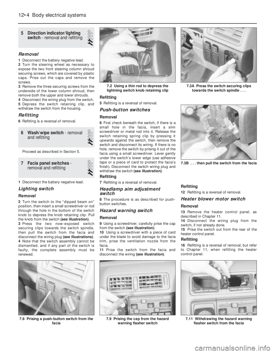
the knob from the switch (see illustration).
3Press the two now-exposed switch
securing clips towards the switch spindle,
then pull the switch from the facia and
disconnect the wiring plug (see illustrations).
4Note that the switch assembly cannot be
dismantled, and if any part of the switch is
faulty, the complete assembly must be
renewed.
Refitting
5Refitting is a reversal of removal.
Push-button switches
Removal
6First check beneath the switch, if there is a
small hole in the facia, insert a slim
screwdriver or metal rod into it. Release the
switch retaining spring clip by pressing it
upwards against the switch, then remove the
switch and disconnect its wiring. If there is no
hole, remove the switch by prising it out of the
facia using a small screwdriver. Lever gently
under the switch’s lower edge (use adhesive
tape or a piece of card to protect the facia’s
finish). Disconnect the switch wiring plug and
withdraw the switch (see illustration).
Refitting
7Refitting is a reversal of removal.
Headlamp aim adjustment
switch
8The procedure is as described for push-
button switches.
Hazard warning switch
Removal
9Using a screwdriver, carefully prise the cap
from the switch (see illustration).
10Using a screwdriver with a piece of card
under the blade to avoid damage to the facia
trim, prise the ventilation nozzle from the
facia.
11Prise the switch from the facia and
disconnect the wiring (see illustration).
Refitting
12Refitting is a reversal of removal.
Heater blower motor switch
Removal
13Remove the heater control panel, as
described in Chapter 11.
14Disconnect the wiring plug from the
switch, if not already done.
15Prise the switch out from the rear of the
heater control panel.
Refitting
16Refitting is a reversal of removal, but refer
to Chapter 11, when refitting the heater
control panel.
12•4Body electrical systems
7.2 Using a thin rod to depress the
lightning switch knob retaining clip
7.3B . . . then pull the switch from the facia
7.11 Withdrawing the hazard warning
flasher switch from the facia7.9 Prising the cap from the hazard
warning flasher switch7.6 Prising a push-button switch from the
facia
7.3A Press the switch securing clips
towards the switch spindle . . .
Page 20 of 525
3To remove the cigarette lighter assembly,
simply pull it from the illumination ring
assembly. If desired, the illumination ring
assembly can be removed, by pulling it from
the housing after depressing the retaining
clips.
Refitting
4Refitting is a reversal of removal.
16Clock - removal and refitting
2
Removal
1Disconnect the battery negative lead.
2Using a thin-bladed screwdriver, carefully
prise the clock from the facia panel.
3Disconnect the wiring plugs and withdraw
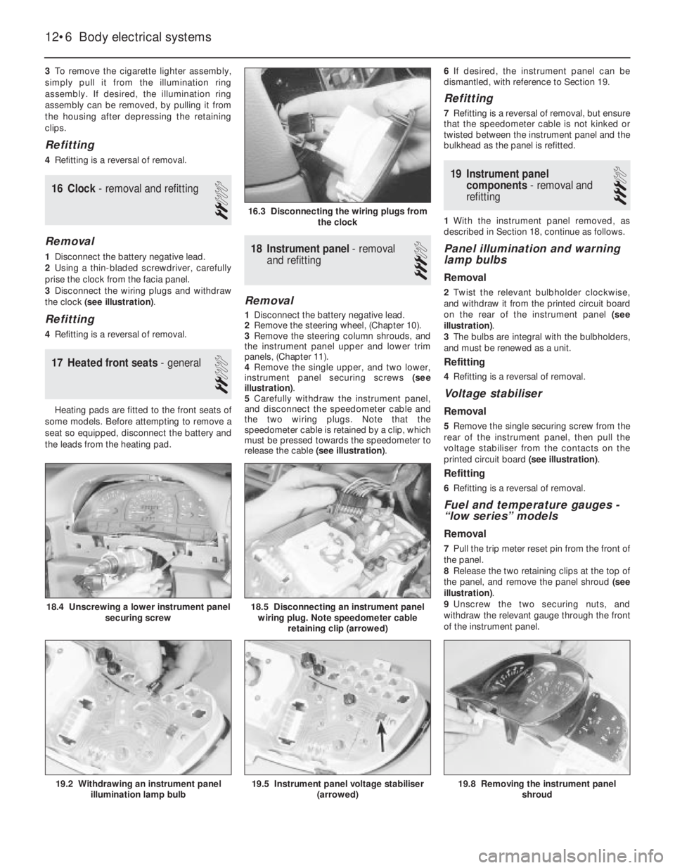
the clock (see illustration).
Refitting
4Refitting is a reversal of removal.
17Heated front seats - general
2
Heating pads are fitted to the front seats of
some models. Before attempting to remove a
seat so equipped, disconnect the battery and
the leads from the heating pad.
18Instrument panel -removal
and refitting
3
Removal
1Disconnect the battery negative lead.
2Remove the steering wheel, (Chapter 10).
3Remove the steering column shrouds, and
the instrument panel upper and lower trim
panels, (Chapter 11).
4Remove the single upper, and two lower,
instrument panel securing screws (see
illustration).
5Carefully withdraw the instrument panel,
and disconnect the speedometer cable and
the two wiring plugs. Note that the
speedometer cable is retained by a clip, which
must be pressed towards the speedometer to
release the cable (see illustration).6If desired, the instrument panel can be
dismantled, with reference to Section 19.
Refitting
7Refitting is a reversal of removal, but ensure
that the speedometer cable is not kinked or
twisted between the instrument panel and the
bulkhead as the panel is refitted.
19Instrument panel
components - removal and
refitting
3
1With the instrument panel removed, as
described in Section 18, continue as follows.
Panel illumination and warning
lamp bulbs
Removal
2Twist the relevant bulbholder clockwise,
and withdraw it from the printed circuit board
on the rear of the instrument panel (see
illustration).
3The bulbs are integral with the bulbholders,
and must be renewed as a unit.
Refitting
4Refitting is a reversal of removal.
Voltage stabiliser
Removal
5Remove the single securing screw from the
rear of the instrument panel, then pull the
voltage stabiliser from the contacts on the
printed circuit board (see illustration).
Refitting
6Refitting is a reversal of removal.
Fuel and temperature gauges -
“low series” models
Removal
7Pull the trip meter reset pin from the front of
the panel.
8Release the two retaining clips at the top of
the panel, and remove the panel shroud (see
illustration).
9Unscrew the two securing nuts, and
withdraw the relevant gauge through the front
of the instrument panel.
12•6Body electrical systems
16.3 Disconnecting the wiring plugs from
the clock
18.5 Disconnecting an instrument panel
wiring plug. Note speedometer cable
retaining clip (arrowed)
19.8 Removing the instrument panel
shroud19.5 Instrument panel voltage stabiliser
(arrowed)19.2 Withdrawing an instrument panel
illumination lamp bulb
18.4 Unscrewing a lower instrument panel
securing screw
Page 39 of 525
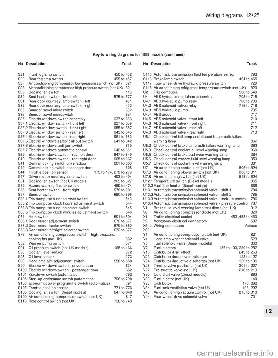
Wiring diagrams 12•25
12
Key to wiring diagrams for 1989 models (continued)
S21Front foglamp switch450 to 452
S22Rear foglamp switch455 to 457
S27Air conditioning compressor low-pressure switch (not UK)821
S28Air conditioning compressor high-pressure switch (not UK)821
S29Cooling fan switch113
S30Seat heater switch - front left575 to 577
S31Rear door courtesy lamp switch - left491
S32Rear door courtesy lamp switch - right492
S35Sunroof travel microswitch692
S36Sunroof travel microswitch694
S37Electric windows switch assembly637 to 663
S37.1Electric window switch - front left637 to 639
S37.2Electric window switch - front right655 to 657
S37.3Electric window switch - rear left643 to 645
S37.4Electric window switch - rear right661 to 663
S37.5Electric windows safety cut-out switch641 to 642
S37.6Electric windows anti-jam switch659
S37.7Electric windows automatic control646 to 651
S39Electric windows switch - rear left door647 to 649
S40Electric windows switch - rear right door665 to 667
S41Central locking switch driver’sdoor601 to 603
S42Central locking switch passenger door605
S44Throttle position sensor173 to 174, 278 to 279
S47Driver’s door courtesy lamp switch493 to 494
S51Cooling fan switch (not UK models)825 to 827
S52Hazard warning flasher switch469 to 474
S55Seat heater switch - front right579 to 581
S57Sunroof switch690 to 696
S63.1Trip computer function reset switch543
S63.2Trip computer clock hours adjustment switch544
S63.3Trip computer function select switch545
S63.5Trip computer clock minutes adjustment switch546
S64Horn switch591 to 594
S68.1Door mirror adjustment switch672 to 677
S68.2Door mirror heater switch679 to 680
S68.3Door mirror left/right selector switch673 to 677
S76Air conditioning compressor switch -high-pressure,
cooling fan (not UK)832
S82Washer pump switch371
S91Oil pressure switch (not UK models)165 to 166
S93Coolant level sensor372
S95Oil level sensor373
S98Headlamp aim adjustment switch556 to 558
S99Electric windows switch - driver’s door634
S100Electric windows switch -passenger door652
S104Kickdown switch (automatics)792
S105Start-up assistance switch (automatics)796 to 798
S106Economy/power programme switch (automatics)791
S107Throttle position sensor 771 to 776
S108Cooling fan switch (Diesel models)847 to 848
S109Air conditioning compressor switch (not UK)817
S110Ride control switch (not UK)738 to 743S115Automatic transmission fluid temperature sensor793
S116Brake lamp switch464 to 465
S117Four-wheel-drive hydraulic pressure switch729
S118Air conditioning refrigerant temperature switch (not UK)829
U2Trip computer538 to 548
U4ABS hydraulic modulator assembly705 to 718
U4.1ABS hydraulic pump relay706 to 709
U4.2ABS solenoid valves relay715 to 718
U4.3ABS hydraulic pump705
U4.4ABS diode717
U4.5ABS solenoid valve - front left710
U4.6ABS solenoid valve - front right711
U4.7ABS solenoid valve - rear left712
U4.8ABS solenoid valve - rear right713
U5.1Check control tail lamp and dipped beam bulb failure
warning lamp362
U5.2Check control brake lamp bulb failure warning lamp 363
U5.3Check control coolant oil level warning lamp360
U5.5Check control brake pad wear warning lamp364
U5.6Check control washer fluid level warning lamp359
U5.7Check control coolant level warning lamp361
U7Air conditioning control unit (not UK)806 to 824
U7.6Air conditioning blower switch (not UK)806 to 811
U7.8Air conditioning switch (not UK)813 to 824
U12.1Temperature switch (Diesel models)865
U12.2Fuel filter heater (Diesel models)866
U13.1Automatic transmission solenoid valve -shift 1784
U13.2Automatic transmission solenoid valve - shift 2785
U13.3Automatic transmission solenoid valve - lock-up control786
U13.4Automatic transmission solenoid valve - pressure control787
V1Brake fluid level warning lamp test diode (not UK)312
V8 Air conditioning compressor diode (not UK)820
X1Trailer electrical socket453 ,458 to 460
X2Accessory electrical connectors587
X5 toWiring connectorsVarious
X62
Y1Air conditioning compressor clutch (not UK)821
Y4Headlamp washer solenoid valve523
Y5Fuel solenoid valve (Diesel models)860
Y7Fuel injectors186 to 193, 280 to 287
Y10Distributor (Hall-effect)249 to 253
Y23Distributor (Inductive discharge)123 to 127
Y24Distributor (Inductive discharge) (not UK)129 to 136
Y26Throttle valve positioner (not UK)201 to 207
Y27Pre-throttle valve (not UK)218 to 219
Y30Cold start valve (Diesel models)863
Y32Fuel injector (not UK)140
Y33Distributor170, 262
Y34Fuel tank ventilation valve (not UK)198, 292
Y43Air conditioning vacuum control (not UK)815 to 818
Y44Four-wheel-drive solenoid valve731 NoDescriptionTrackNoDescriptionTrack
Page 93 of 525
8Alternator drivebelt -
removal, refitting and adjusting
2
V-belt type (not-ribbed)
Removal
1Disconnect the air inlet trunking from the air
cleaner, and the air box or throttle body, as
applicable, and remove it for improved
access.
2Correct tensioning of the drivebelt will
ensure that it has a long life. Beware,
however, of overtightening, as this can cause
excessive wear in the alternator.
3The belt should be inspected regularly, and
if it is found to be worn, frayed or cracked, it
should be renewed as a precaution against
breakage in service. It is advisable to carry a
spare drivebelt of the correct type in the
vehicle always.
4On models with power steering, the
alternator drivebelt also drives the power
steering pump.
5To remove the belt, on 1.8 and 2.0 litre
models first remove the power steering pump
drivebelt, as described in Chapter 10.
6Loosen the two alternator mounting nuts
and bolts sufficiently to allow the alternator to
be pivoted in towards the engine.
7Slide the belt from the pulleys.
Refitting
8Ensure that the correct type of belt is used,
if it is being renewed. Fit the belt around the
pulleys. Take up the slack in the belt byswinging the alternator away from the engine
and lightly tightening the mounting nuts and
bolts.
Adjusting
9Although special tools are available for
measuring the belt tension, a good
approximation can be achieved if the belt is
tensioned so that there is approximately 13.0
mm (0.5 in) of free movement under firm
thumb pressure at the mid-point of the
longest run between pulleys.
10With the mounting bolts just holding the
unit, lever the alternator away from the engine
using a wooden lever at the mounting bracket
end until the correct tension is achieved. Then
tighten the mounting nuts and bolts. On no
account lever at the free end of the alternator,
as serious internal damage could be caused.11Where applicable, refit and tension the
power steering pump drivebelt, as described
in Chapter 10.
12Refit the air inlet trunking.
13When a new belt has been fitted, it will
probably stretch slightly when it is first run,
and the tension should be rechecked and if
necessary adjusted after approximately 250
miles (400 km).
Ribbed V-belt type
General
14Later models equipped with power
steering are fitted with a ribbed V-belt type
drivebelt in conjunction with an automatic
tensioning roller. Once the belt is installed, no
further adjustment is necessary as the correct
tension is maintained by the automatic
tensioning roller. Removal and refitting
procedures are as follows.
Removal
15For improved access, remove the air
cleaner assembly and air inlet trunking.
16If the original drivebelt is to be refitted, mark
the rotational direction on the belt with chalk.
17Using a spanner or socket on the
automatic tensioning roller hexagon, turn the
tensioning roller clockwise (as viewed from the
right-hand side of the car) and hold it in this
position. With the drivebelt tension released,
slip the drivebelt off the pulleys, then allow the
tensioner to return to its original position.
18Support the engine under the sump with a
jack and interposed block of wood.
19From under the car, unbolt the right-hand
engine mounting block from the body.
20Lower the engine support jack just
sufficiently to allow the drivebelt to be
withdrawn from between the mounting block
and the body.
Refitting
21Slip the new drivebelt between the
mounting block and body then raise the
engine, by means of the jack, to its original
position.
22Clean the threads of the mounting block
retaining bolts, apply locking fluid, and refit
the bolts. Tighten the bolts to the specified
torque (see Chapter 2A).
23Rotate the automatic tensioner roller anti-
clockwise and route the drivebelt around the
pulleys as shown (see illustration). With the
belt correctly positioned, release the tensioner
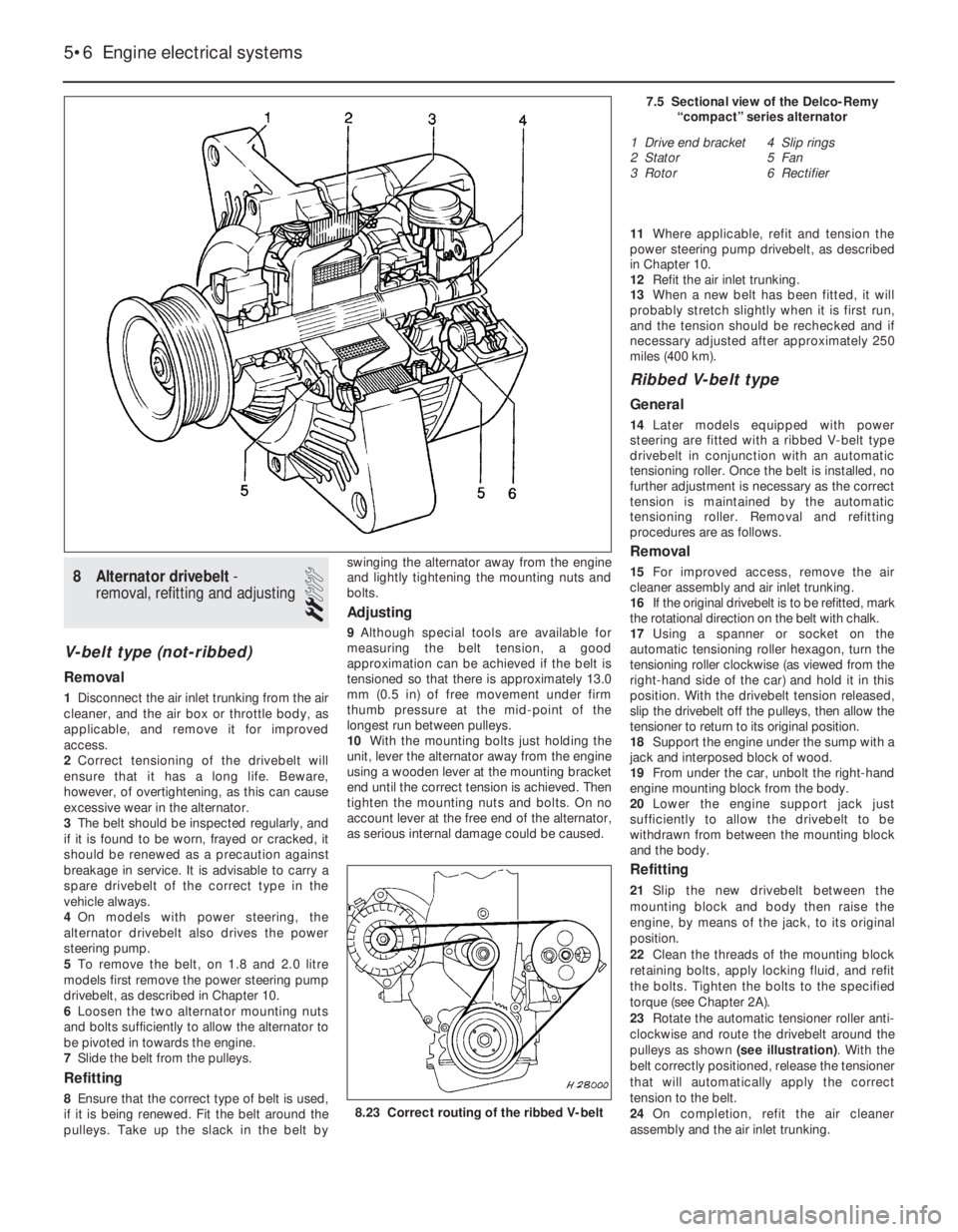
that will automatically apply the correct
tension to the belt.
24On completion, refit the air cleaner
assembly and the air inlet trunking.
5•6Engine electrical systems
7.5 Sectional view of the Delco-Remy
“compact” series alternator
1 Drive end bracket
2 Stator
3 Rotor4 Slip rings
5 Fan
6 Rectifier
8.23 Correct routing of the ribbed V-belt
Page 114 of 525
27Door mirror - removal,
overhaul and refitting
3
Glass renewal
1If desired, the mirror glass can be removed
for renewal without removing the mirror. On
models with electric mirrors, disconnect the
battery negative lead.
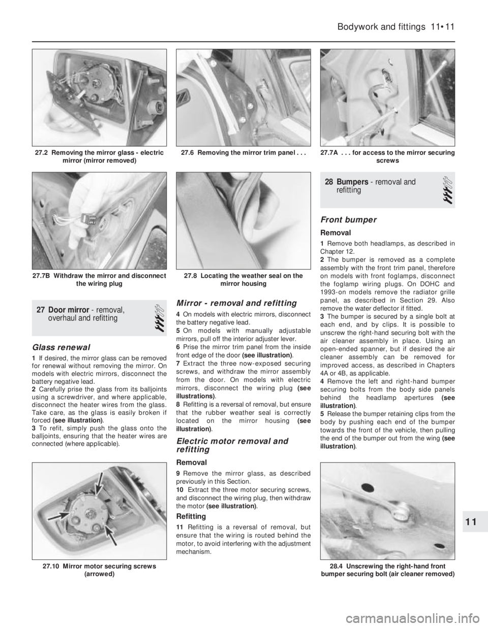
2Carefully prise the glass from its balljoints
using a screwdriver, and where applicable,
disconnect the heater wires from the glass.
Take care, as the glass is easily broken if
forced (see illustration).
3To refit, simply push the glass onto the
balljoints, ensuring that the heater wires are
connected (where applicable).
Mirror -removal and refitting
4On models with electric mirrors, disconnect
the battery negative lead.
5On models with manually adjustable
mirrors, pull off the interior adjuster lever.
6Prise the mirror trim panel from the inside
front edge of the door (see illustration).
7Extract the three now-exposed securing
screws, and withdraw the mirror assembly
from the door. On models with electric
mirrors, disconnect the wiring plug (see
illustrations).
8Refitting is a reversal of removal, but ensure
that the rubber weather seal is correctly
located on the mirror housing (see
illustration).
Electric motor removal and
refitting
Removal
9Remove the mirror glass, as described
previously in this Section.
10Extract the three motor securing screws,
and disconnect the wiring plug, then withdraw
the motor (see illustration).
Refitting
11Refitting is a reversal of removal, but
ensure that the wiring is routed behind the
motor, to avoid interfering with the adjustment
mechanism.
28Bumpers - removal and
refitting
3
Front bumper
Removal
1Remove both headlamps, as described in
Chapter 12.
2The bumper is removed as a complete
assembly with the front trim panel, therefore
on models with front foglamps, disconnect
the foglamp wiring plugs. On DOHC and
1993-on models remove the radiator grille
panel, as described in Section 29. Also
remove the water deflector if fitted.
3The bumper is secured by a single bolt at
each end, and by clips. It is possible to
unscrew the right-hand securing bolt with the
air cleaner assembly in place. Using an
open-ended spanner, but if desired the air
cleaner assembly can be removed for
improved access, as described in Chapters
4A or 4B, as applicable.
4Remove the left and right-hand bumper
securing bolts from the body side panels
behind the headlamp apertures (see
illustration).
5Release the bumper retaining clips from the
body by pushing each end of the bumper
towards the front of the vehicle, then pulling
the end of the bumper out from the wing (see
illustration).
Bodywork and fittings 11•11
27.7A . . . for access to the mirror securing
screws
28.4 Unscrewing the right-hand front
bumper securing bolt (air cleaner removed)27.10 Mirror motor securing screws
(arrowed)
27.8 Locating the weather seal on the
mirror housing27.7B Withdraw the mirror and disconnect
the wiring plug
27.6 Removing the mirror trim panel . . .27.2 Removing the mirror glass - electric
mirror (mirror removed)
11
Page 115 of 525
6Carefully withdraw the bumper from the
vehicle.
Refitting
7Refitting is a reversal of removal.
Rear bumper
Removal
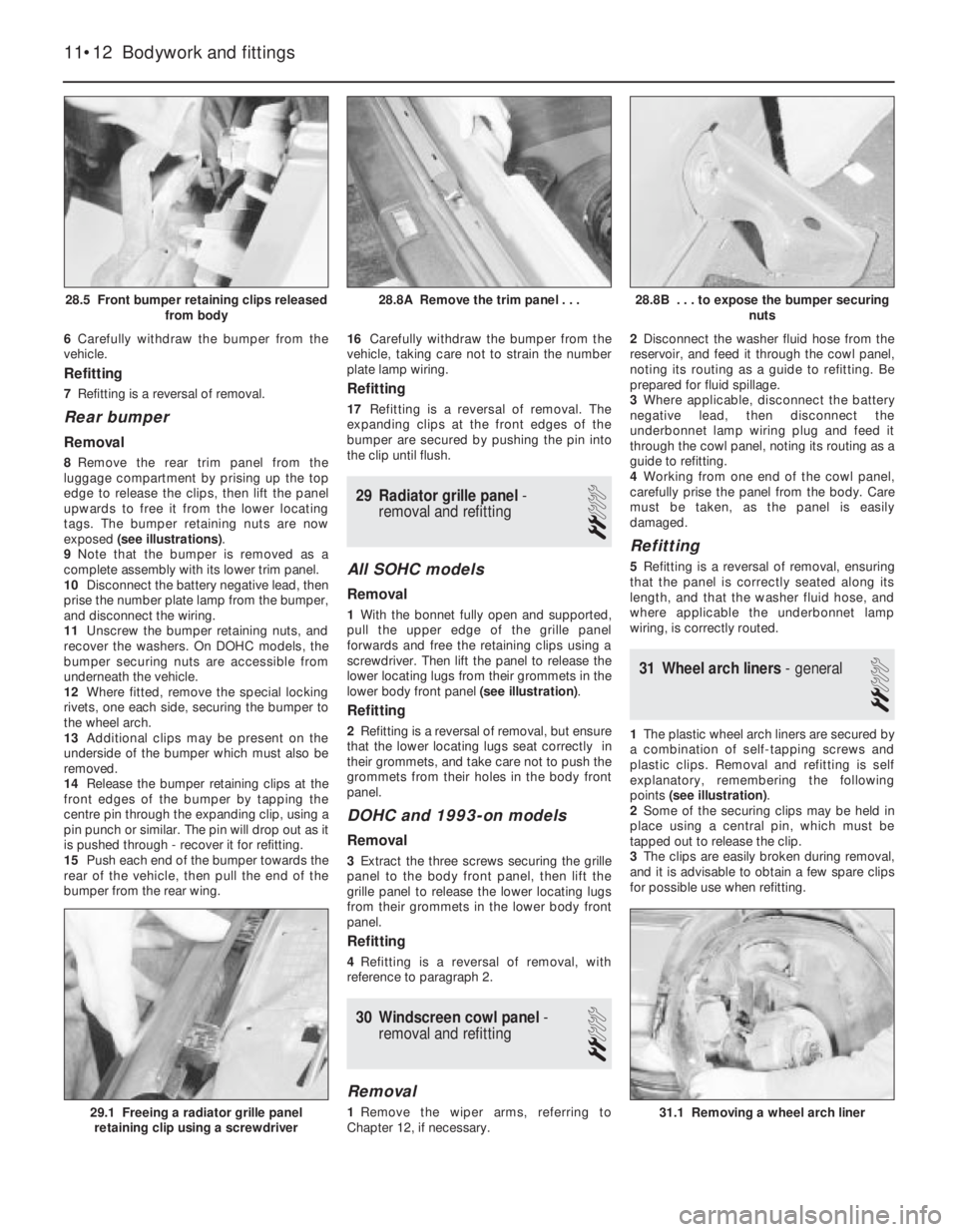
8Remove the rear trim panel from the
luggage compartment by prising up the top
edge to release the clips, then lift the panel
upwards to free it from the lower locating
tags. The bumper retaining nuts are now
exposed (see illustrations).
9Note that the bumper is removed as a
complete assembly with its lower trim panel.
10Disconnect the battery negative lead, then
prise the number plate lamp from the bumper,
and disconnect the wiring.
11Unscrew the bumper retaining nuts, and
recover the washers. On DOHC models, the
bumper securing nuts are accessible from
underneath the vehicle.
12Where fitted, remove the special locking
rivets, one each side, securing the bumper to
the wheel arch.
13Additional clips may be present on the
underside of the bumper which must also be
removed.
14Release the bumper retaining clips at the
front edges of the bumper by tapping the
centre pin through the expanding clip, using a
pin punch or similar. The pin will drop out as it
is pushed through - recover it for refitting.
15Push each end of the bumper towards the
rear of the vehicle, then pull the end of the
bumper from the rear wing.16Carefully withdraw the bumper from the
vehicle, taking care not to strain the number
plate lamp wiring.
Refitting
17Refitting is a reversal of removal. The
expanding clips at the front edges of the
bumper are secured by pushing the pin into
the clip until flush.
29Radiator grille panel -
removal and refitting
2
All SOHC models
Removal
1With the bonnet fully open and supported,
pull the upper edge of the grille panel
forwards and free the retaining clips using a
screwdriver. Then lift the panel to release the
lower locating lugs from their grommets in the
lower body front panel (see illustration).
Refitting
2Refitting is a reversal of removal, but ensure
that the lower locating lugs seat correctly in
their grommets, and take care not to push the
grommets from their holes in the body front
panel.
DOHC and 1993-on models
Removal
3Extract the three screws securing the grille
panel to the body front panel, then lift the
grille panel to release the lower locating lugs
from their grommets in the lower body front
panel.
Refitting
4Refitting is a reversal of removal, with
reference to paragraph 2.
30Windscreen cowl panel -
removal and refitting
2
Removal
1Remove the wiper arms, referring to
Chapter 12, if necessary.2Disconnect the washer fluid hose from the
reservoir, and feed it through the cowl panel,
noting its routing as a guide to refitting. Be
prepared for fluid spillage.
3Where applicable, disconnect the battery
negative lead, then disconnect the
underbonnet lamp wiring plug and feed it
through the cowl panel, noting its routing as a
guide to refitting.
4Working from one end of the cowl panel,
carefully prise the panel from the body. Care
must be taken, as the panel is easily
damaged.
Refitting
5Refitting is a reversal of removal, ensuring
that the panel is correctly seated along its
length, and that the washer fluid hose, and
where applicable the underbonnet lamp
wiring, is correctly routed.
31Wheel arch liners - general
2
1The plastic wheel arch liners are secured by
a combination of self-tapping screws and
plastic clips. Removal and refitting is self
explanatory, remembering the following
points (see illustration).
2Some of the securing clips may be held in
place using a central pin, which must be
tapped out to release the clip.
3The clips are easily broken during removal,
and it is advisable to obtain a few spare clips
for possible use when refitting.
11•12Bodywork and fittings
28.8B . . . to expose the bumper securing
nuts
31.1 Removing a wheel arch liner29.1 Freeing a radiator grille panel
retaining clip using a screwdriver
28.8A Remove the trim panel . . .28.5 Front bumper retaining clips released
from body
Page 119 of 525

37Facia panels - removal and
refitting
3
Footwell trim panels
Removal
1The lower footwell trim panels on the
driver’s and passenger sides are secured by
turnbuckle type plastic clips.2To remove a panel, use a screwdriver to
turn the heads of the clips through 90°(see
illustration), then withdraw the panel from the
facia.
Refitting
3Refitting is a reversal of removal.
Driver’s side lower facia panel
Removal
4Open the flap covering the fusebox to
expose the four lower facia panel securing
screws.
5Remove the four screws, then lower the
panel and pull it towards the driver’s door to
release the two securing clips. Withdraw the
panel from the facia (see illustrations).
Refitting
6Refitting is a reversal of removal.
Steering column shrouds
Removal
7On models with an adjustable tilt steering
column, move the column to its fully raised
position, then unscrew the adjuster lever (see
illustration).
8Turn the steering wheel as necessary to
expose one of the front steering column
shroud securing screw covers.
9Prise out the cover, and remove the column
shroud securing screw, then turn the steering
wheel to enable the remaining cover and
screw to be removed (see illustrations).
10Remove the three securing screws from
the underside of the lower column shroud,
then remove the lower and upper shrouds
(see illustrations).
11•16Bodywork and fittings
37.2 Releasing a footwell trim panel
securing clip37.5B . . . then withdraw the lower facia
panel
37.10C . . . and upper shrouds (steering
wheel removed)37.10B . . . then remove the lower . . .37.10A Remove the three lower column
shroud securing screws . . .
37.9B . . . then remove the front column
shroud securing screws37.9A Prise out the covers . . .37.7 Removing the column adjuster lever
37.5A Remove the four securing screws
from the fusebox aperture . . .
Before removing any of the
facia panels, the battery
negative lead should be
disconnected, as several
permanently live feed wires are routed
behind the facia.