1988 OPEL CALIBRA tow
[x] Cancel search: towPage 207 of 525
30With the engine removed, the
transmission can be supported by placing a
length of wood between the bellhousing and
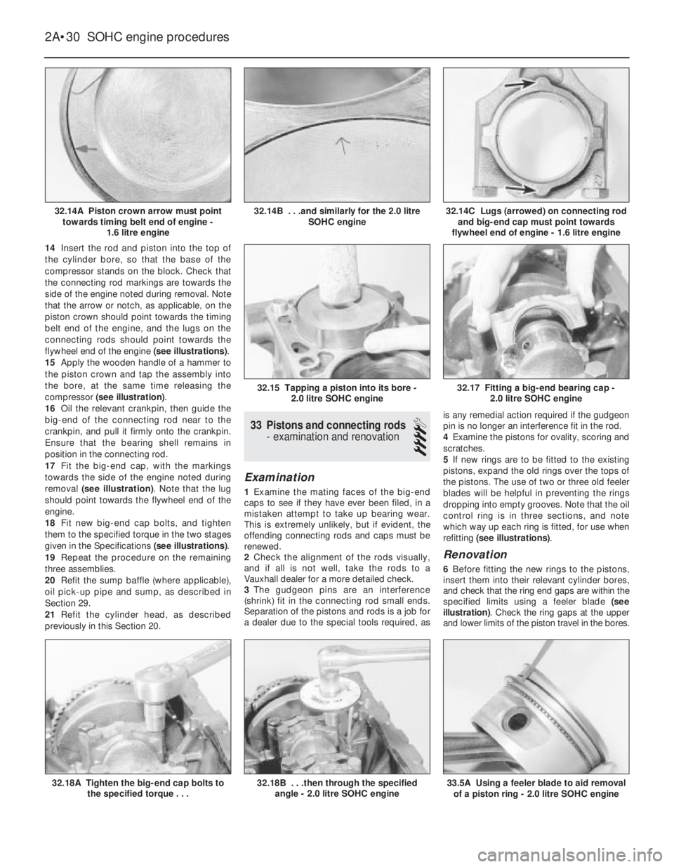
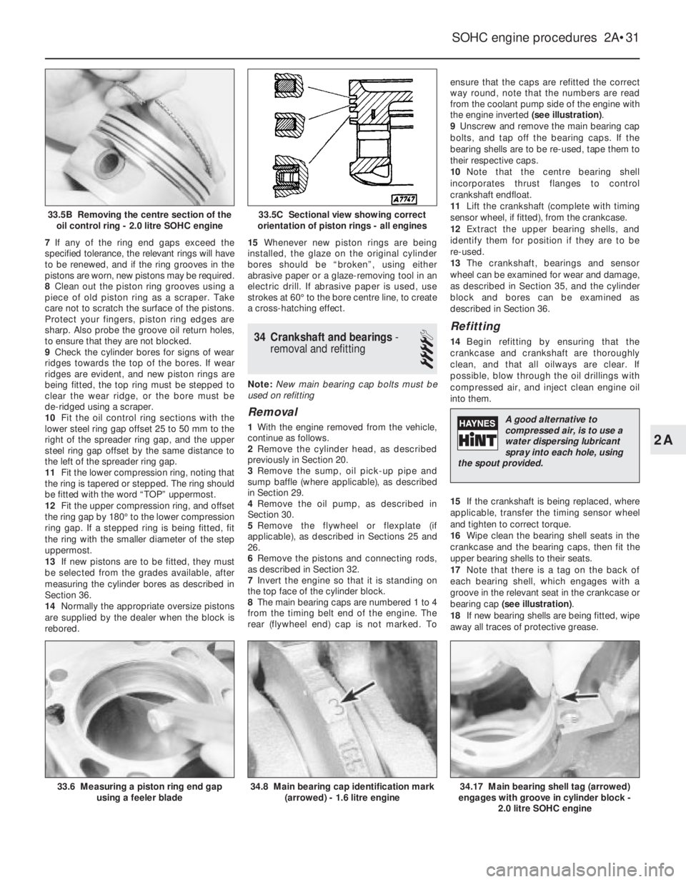
the front suspension subframe. Once the
wooden support is in place, remove the trolley
jack from under the transmission.
Refitting
Note: New left and right-hand
engine/transmission mounting-to-body bolts
must be used on refitting.
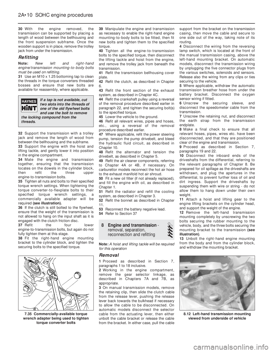
31Use an M10 x 1.25 bottoming tap to clean
the threads in the torque converters threaded
bosses and ensure that new bolts are
available for reassembly, where applicable.
32Support the transmission with a trolley
jack and remove the length of wood from
between the bellhousing and the subframe.
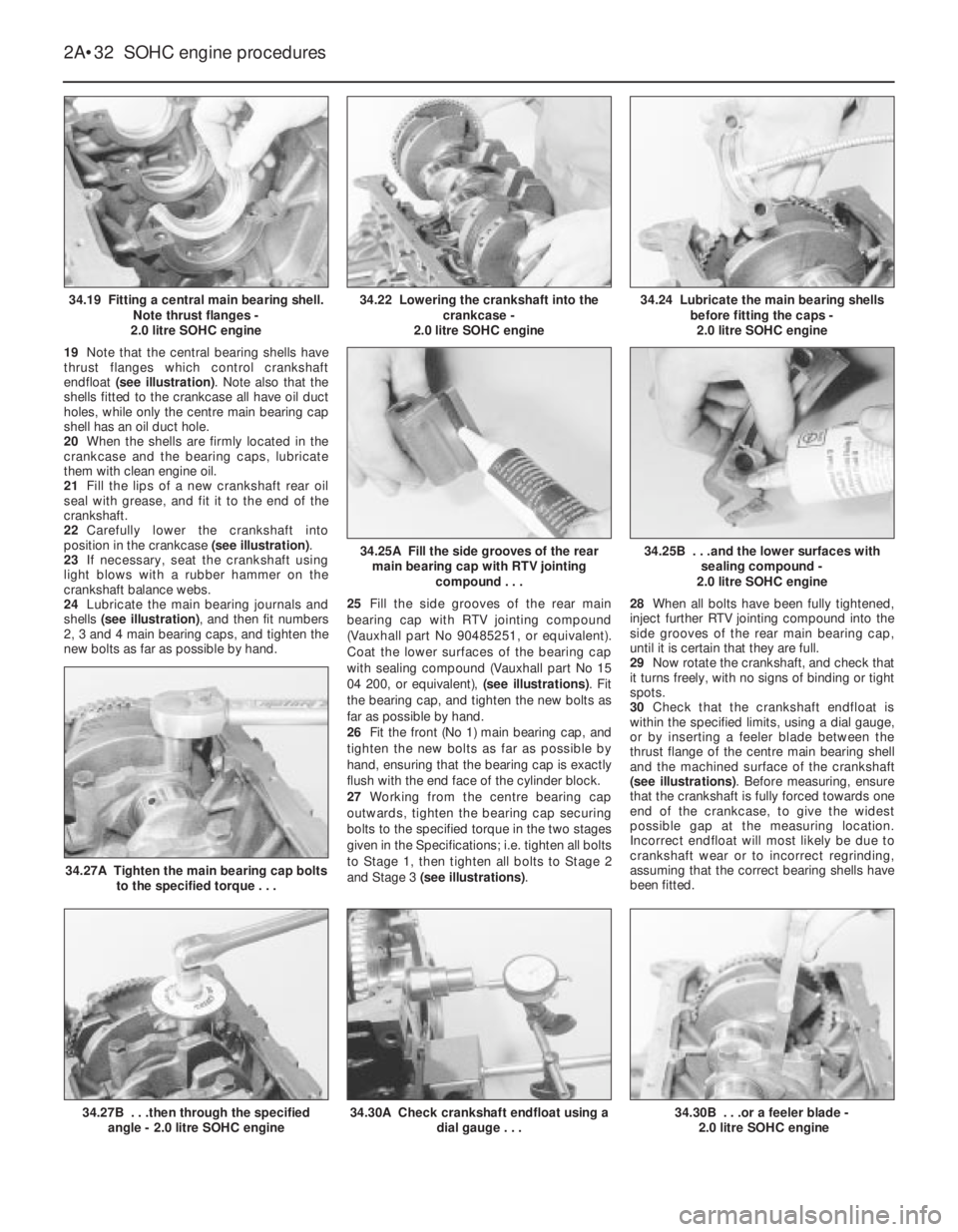
33Support the engine with the hoist and
lifting tackle, and gently lower it into position
in the engine compartment.
34Mate the engine and transmission
together, ensuring that the transmission
locates on the dowels in the cylinder block,
then refit the three upper
engine-to-transmission bolts.
35Tighten all nuts and bolts to their specified
torque wrench settings. When tightening the
torque converter-to-flexplate bolts to their
specified torque wrench settings, a
commercially available adapter will be
required (see illustration).
36If the clutch is still bolted to the flywheel,
ensure that the weight of the transmission is
not allowed to hang on the input shaft as it is
engaged with the clutch friction disc.
37Refit the four lower
engine-to-transmission bolts, but again do not
fully tighten them at this stage.
38Fit the right-hand engine mounting
bracket to the cylinder block, and tighten the
securing bolts to the specified torque.39Manipulate the engine and transmission
as necessary to enable the right-hand engine
mounting-to-body bolts to be fitted, then fit
new bolts and tighten them to the specified
torque.
40Tighten all the engine-to-transmission
bolts to the specified torque, then disconnect
the lifting tackle and hoist from the engine,
and remove the trolley jack from beneath the
transmission.
41Refit the transmission bellhousing cover
plate.
42Refit the clutch, as described in Chapter
6.
43Refit the front section of the exhaust
system, as described in Chapter 4C.
44Refit the crankshaft pulley using a reversal
of the removal procedure described earlier in
paragraph 22, and tighten the securing bolt(s)
to the specified torque.
45Lower the vehicle to the ground.
46Refit all relevant wires, pipes and hoses,
etc., using a reversal of the removal
procedure described earlier.
47Where applicable, refit the power steering
pump, tension the pump drivebelt, and bleed
the hydraulic fluid circuit, as described in
Chapter 10.
48Refit the alternator and tension the
drivebelt, as described in Chapter 5.
49Refit the air cleaner components, referring
to Chapter 4A or 4B, if necessary. On
carburettor models reconnect the hot air hose
to the exhaust manifold hot air shroud.
50Fit a new oil filter (if not already replaced),
and fill the engine with oil, as described in
Chapter 1.
51Refit the radiator and refill the cooling
system, as described in Chapter 3.
52Refit the bonnet as described in Chapter
11.
53Reconnect the battery negative lead.
54Refer to Section 37
8Engine and transmission -
removal, separation,
reconnection and refitting
4
Note: A hoist and lifting tackle will be required
for this operation
Removal
1Proceed as described in Section 7,
paragraphs 1 to 18 inclusive.
2Working in the engine compartment,
remove the gear selector linkage, as
described in Chapters 7A and 7B, as
appropriate.
3On manual transmission models, remove
the retaining clip, then slide the clutch cable
from the release lever, pushing the release
lever back towards the bulkhead if necessary
to allow the cable to be disconnected. On
automatic models disconnect the selector
cable from the actuating lever, then either
unbolt the cable bracket or release the cable
from the bracket. In either case, pull the cablesupport from the bracket on the transmission
casing, then move the cable and secure to
one side out of the way, taking note of its
routing.
4Disconnect the wiring from the reversing
lamp switch, which is located at the front of
the manual transmission casing, above the
left-hand mounting bracket. On automatic
models, disconnect the transmission wiring
by unplugging the five connector plugs from
the various switches, solenoids and sensors.
Release also the wiring from any clips or ties
securing to the vehicle.
5Where applicable, withdraw the automatic
transmission breather hose from under the
battery bracket. Disconnect the oxygen
sensor wiring if fitted.
6Unscrew the securing sleeve, and
disconnect the speedometer cable from the
transmission.
7Unscrew the retaining nut, and disconnect
the earth strap from the transmission
endplate.
8Make a final check to ensure that all
relevant hoses, pipes, wires etc. have been
disconnected, and that they are positioned
clear of the engine and transmission.
9Proceed as described in Section 7,
paragraphs 19 and 22.
10Disconnect the inboard ends of the
driveshafts from the differential, referring to
the relevant paragraphs of Chapter 8. Be
prepared for oil spillage as the driveshafts are
withdrawn, and plug the apertures in the
differential, to prevent further loss of oil and
dirt ingress. Support the driveshafts by
suspending them with wire or string - do not
allow them to hang down under their own
weight.
11Attach a hoist and lifting gear to the
engine lifting brackets on the cylinder head,
and support the weight of the engine.
12Remove the left-hand transmission
mounting completely by unscrewing the two
bolts securing the rubber mounting to the
vehicle, body, and the three bolts securing the
mounting bracket to the transmission (see
illustration).
13Unbolt the right-hand engine mounting
from the body and from the cylinder block,
and withdraw the mounting bracket.
2A•10SOHC engine procedures
8.12 Left-hand transmission mounting
viewed from underside of vehicle7.35 Commercially-available torque
wrench adapter being used to tighten
torque converter bolts
If a tap is not available, cut
two slots into the threads of
one of the old flywheel bolts
and use the bolt to remove
the locking compound from the
threads.
Page 227 of 525
14Insert the rod and piston into the top of
the cylinder bore, so that the base of the
compressor stands on the block. Check that
the connecting rod markings are towards the
side of the engine noted during removal. Note
that the arrow or notch, as applicable, on the
piston crown should point towards the timing
belt end of the engine, and the lugs on the
connecting rods should point towards the
flywheel end of the engine (see illustrations).
15Apply the wooden handle of a hammer to
the piston crown and tap the assembly into
the bore, at the same time releasing the
compressor (see illustration).
16Oil the relevant crankpin, then guide the
big-end of the connecting rod near to the
crankpin, and pull it firmly onto the crankpin.
Ensure that the bearing shell remains in
position in the connecting rod.
17Fit the big-end cap, with the markings
towards the side of the engine noted during
removal (see illustration). Note that the lug
should point towards the flywheel end of the
engine.
18Fit new big-end cap bolts, and tighten
them to the specified torque in the two stages
given in the Specifications (see illustrations).
19Repeat the procedure on the remaining
three assemblies.
20Refit the sump baffle (where applicable),
oil pick-up pipe and sump, as described in
Section 29.
21Refit the cylinder head, as described
previously in this Section 20.
33Pistons and connecting rods
-examination and renovation
4
Examination
1Examine the mating faces of the big-end
caps to see if they have ever been filed, in a
mistaken attempt to take up bearing wear.
This is extremely unlikely, but if evident, the
offending connecting rods and caps must be
renewed.
2Check the alignment of the rods visually,
and if all is not well, take the rods to a
Vauxhall dealer for a more detailed check.
3The gudgeon pins are an interference
(shrink) fit in the connecting rod small ends.
Separation of the pistons and rods is a job for
a dealer due to the special tools required, asis any remedial action required if the gudgeon
pin is no longer an interference fit in the rod.
4Examine the pistons for ovality, scoring and
scratches.
5If new rings are to be fitted to the existing
pistons, expand the old rings over the tops of
the pistons. The use of two or three old feeler
blades will be helpful in preventing the rings
dropping into empty grooves. Note that the oil
control ring is in three sections, and note
which way up each ring is fitted, for use when
refitting (see illustrations).
Renovation
6Before fitting the new rings to the pistons,
insert them into their relevant cylinder bores,
and check that the ring end gaps are within the
specified limits using a feeler blade (see
illustration). Check the ring gaps at the upper
and lower limits of the piston travel in the bores.
2A•30SOHC engine procedures
32.14A Piston crown arrow must point
towards timing belt end of engine -
1.6 litre engine32.14C Lugs (arrowed) on connecting rod
and big-end cap must point towards
flywheel end of engine - 1.6 litre engine
33.5A Using a feeler blade to aid removal
of a piston ring - 2.0 litre SOHC engine32.18B . . .then through the specified
angle - 2.0 litre SOHC engine32.18A Tighten the big-end cap bolts to
the specified torque . . .
32.17 Fitting a big-end bearing cap -
2.0 litre SOHC engine32.15 Tapping a piston into its bore -
2.0 litre SOHC engine
32.14B . . .and similarly for the 2.0 litre
SOHC engine
Page 228 of 525
7If any of the ring end gaps exceed the
specified tolerance, the relevant rings will have
to be renewed, and if the ring grooves in the
pistons are worn, new pistons may be required.
8Clean out the piston ring grooves using a
piece of old piston ring as a scraper. Take
care not to scratch the surface of the pistons.
Protect your fingers, piston ring edges are
sharp. Also probe the groove oil return holes,
to ensure that they are not blocked.
9Check the cylinder bores for signs of wear
ridges towards the top of the bores. If wear
ridges are evident, and new piston rings are
being fitted, the top ring must be stepped to
clear the wear ridge, or the bore must be
de-ridged using a scraper.
10Fit the oil control ring sections with the
lower steel ring gap offset 25 to 50 mm to the
right of the spreader ring gap, and the upper
steel ring gap offset by the same distance to
the left of the spreader ring gap.
11Fit the lower compression ring, noting that
the ring is tapered or stepped. The ring should
be fitted with the word “TOP” uppermost.
12Fit the upper compression ring, and offset
the ring gap by 180°to the lower compression
ring gap. If a stepped ring is being fitted, fit
the ring with the smaller diameter of the step
uppermost.
13If new pistons are to be fitted, they must
be selected from the grades available, after
measuring the cylinder bores as described in
Section 36.
14Normally the appropriate oversize pistons
are supplied by the dealer when the block is
rebored.15Whenever new piston rings are being
installed, the glaze on the original cylinder
bores should be “broken”, using either
abrasive paper or a glaze-removing tool in an
electric drill. If abrasive paper is used, use
strokes at 60°to the bore centre line, to create
a cross-hatching effect.
34Crankshaft and bearings -
removal and refitting
4
Note: New main bearing cap bolts must be
used on refitting
Removal
1With the engine removed from the vehicle,
continue as follows.
2Remove the cylinder head, as described
previously in Section 20.
3Remove the sump, oil pick-up pipe and
sump baffle (where applicable), as described
in Section 29.
4Remove the oil pump, as described in
Section 30.
5Remove the flywheel or flexplate (if
applicable), as described in Sections 25 and
26.
6Remove the pistons and connecting rods,
as described in Section 32.
7Invert the engine so that it is standing on
the top face of the cylinder block.
8The main bearing caps are numbered 1 to 4
from the timing belt end of the engine. The
rear (flywheel end) cap is not marked. Toensure that the caps are refitted the correct
way round, note that the numbers are read
from the coolant pump side of the engine with
the engine inverted (see illustration).
9Unscrew and remove the main bearing cap
bolts, and tap off the bearing caps. If the
bearing shells are to be re-used, tape them to
their respective caps.
10Note that the centre bearing shell
incorporates thrust flanges to control
crankshaft endfloat.
11Lift the crankshaft (complete with timing
sensor wheel, if fitted), from the crankcase.
12Extract the upper bearing shells, and
identify them for position if they are to be
re-used.
13The crankshaft, bearings and sensor
wheel can be examined for wear and damage,
as described in Section 35, and the cylinder
block and bores can be examined as
described in Section 36.
Refitting
14Begin refitting by ensuring that the
crankcase and crankshaft are thoroughly
clean, and that all oilways are clear. If
possible, blow through the oil drillings with
compressed air, and inject clean engine oil
into them.
15If the crankshaft is being replaced, where
applicable, transfer the timing sensor wheel
and tighten to correct torque.
16Wipe clean the bearing shell seats in the
crankcase and the bearing caps, then fit the
upper bearing shells to their seats.
17Note that there is a tag on the back of
each bearing shell, which engages with a
groove in the relevant seat in the crankcase or
bearing cap (see illustration).
18If new bearing shells are being fitted, wipe
away all traces of protective grease.
SOHC engine procedures 2A•31
33.6 Measuring a piston ring end gap
using a feeler blade34.8 Main bearing cap identification mark
(arrowed) - 1.6 litre engine34.17 Main bearing shell tag (arrowed)
engages with groove in cylinder block -
2.0 litre SOHC engine
33.5C Sectional view showing correct
orientation of piston rings - all engines33.5B Removing the centre section of the
oil control ring - 2.0 litre SOHC engine
2A
A good alternative to
compressed air, is to use a
water dispersing lubricant
spray into each hole, using
the spout provided.
Page 229 of 525
19Note that the central bearing shells have
thrust flanges which control crankshaft
endfloat (see illustration). Note also that the
shells fitted to the crankcase all have oil duct
holes, while only the centre main bearing cap
shell has an oil duct hole.
20When the shells are firmly located in the
crankcase and the bearing caps, lubricate
them with clean engine oil.
21Fill the lips of a new crankshaft rear oil
seal with grease, and fit it to the end of the
crankshaft.
22Carefully lower the crankshaft into
position in the crankcase (see illustration).
23If necessary, seat the crankshaft using
light blows with a rubber hammer on the
crankshaft balance webs.
24Lubricate the main bearing journals and
shells (see illustration), and then fit numbers
2, 3 and 4 main bearing caps, and tighten the
new bolts as far as possible by hand.25Fill the side grooves of the rear main
bearing cap with RTV jointing compound
(Vauxhall part No 90485251, or equivalent).
Coat the lower surfaces of the bearing cap
with sealing compound (Vauxhall part No 15
04 200, or equivalent), (see illustrations). Fit
the bearing cap, and tighten the new bolts as
far as possible by hand.
26Fit the front (No 1) main bearing cap, and
tighten the new bolts as far as possible by
hand, ensuring that the bearing cap is exactly
flush with the end face of the cylinder block.
27Working from the centre bearing cap
outwards, tighten the bearing cap securing
bolts to the specified torque in the two stages
given in the Specifications; i.e. tighten all bolts
to Stage 1, then tighten all bolts to Stage 2
and Stage 3 (see illustrations).28When all bolts have been fully tightened,
inject further RTV jointing compound into the
side grooves of the rear main bearing cap,
until it is certain that they are full.
29Now rotate the crankshaft, and check that
it turns freely, with no signs of binding or tight
spots.
30Check that the crankshaft endfloat is
within the specified limits, using a dial gauge,
or by inserting a feeler blade between the
thrust flange of the centre main bearing shell
and the machined surface of the crankshaft
(see illustrations). Before measuring, ensure
that the crankshaft is fully forced towards one
end of the crankcase, to give the widest
possible gap at the measuring location.
Incorrect endfloat will most likely be due to
crankshaft wear or to incorrect regrinding,
assuming that the correct bearing shells have
been fitted.
2A•32SOHC engine procedures
34.19 Fitting a central main bearing shell.
Note thrust flanges -
2.0 litre SOHC engine34.24 Lubricate the main bearing shells
before fitting the caps -
2.0 litre SOHC engine
34.30B . . .or a feeler blade -
2.0 litre SOHC engine
34.27A Tighten the main bearing cap bolts
to the specified torque . . .
34.27B . . .then through the specified
angle - 2.0 litre SOHC engine34.30A Check crankshaft endfloat using a
dial gauge . . .
34.25B . . .and the lower surfaces with
sealing compound -
2.0 litre SOHC engine34.25A Fill the side grooves of the rear
main bearing cap with RTV jointing
compound . . .
34.22 Lowering the crankshaft into the
crankcase -
2.0 litre SOHC engine
Page 234 of 525
level in the expansion tank, and top-up if
necessary. Note that the system must be cold
before an accurate level is indicated in the
expansion tank. If the expansion tank cap is
removed while the engine is still warm, cover
the cap with a thick cloth and unscrew the
cap slowly, to gradually relieve the system
pressure. Take care to avoid scalding by
steam or coolant escaping from the
pressurised system.
9On DOHC models, refit the engine
undershield on completion.
5Coolant mixture -general
1It is important to use an antifreeze mixture
in the cooling system all year round, to
prevent corrosion of the alloy engine
components. The coolant mixture should be
made up from clean, preferably soft, tap
water, and a good quality antifreeze
containing corrosion inhibitor. Ensure that the
antifreeze is ethylene glycol based, as the
cheaper methanol based types evaporate
over a period of time.
2The proportions of water and antifreeze
used will depend on the degree of protection
required. A coolant mixture containing 25%
antifreeze should be regarded as the
minimum strength required to maintain good
anti-corrosion properties. Details of the
degree of protection provided against freezing
will be supplied with the antifreeze by the
manufacturers. For absolute protection, use a
50% antifreeze mixture.
3The coolant mixture should be renewed
every two years, as the corrosion inhibitors
will deteriorate with time.
4Before filling the system with fresh coolant,
drain and flush the system, as described in
Sections 2 and 3, and check that all hoses are
secure and that the clips are tight. Antifreeze
has a searching action, and will leak morerapidly than plain water.
5Refill the system as described in Section 4.
All future topping-up should be carried out
using a coolant mixture of the same
proportions as that used to initially fill the
system.
6Do not use antifreeze in the windscreen
wash system, as it will attack the vehicle
paintwork. Note that antifreeze is poisonous,
and must be handled with due care.
6Radiator (manual
transmission) -removal and
refitting
3
Removal
1The radiator can be removed complete with
the coolant fan and shroud if there is no need
to disturb the fan. If desired, the fan and its
shroud can be removed from the radiator,
with reference to Section 12.
2Drain the cooling system, as described in
Section 2.
3Disconnect the radiator top hose and the
expansion tank at the radiator.
4Disconnect the battery negative lead, then
disconnect the wiring from the cooling fan
switch, located at the bottom right-hand side
of the radiator.5Disconnect the cooling fan wiring
connector, noting its location for use when
refitting.
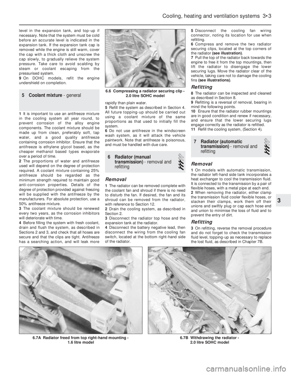
6Compress and remove the two radiator
securing clips, located at the top corners of
the radiator (see illustration).
7Pull the top of the radiator back towards the
engine to free it from the top mountings, then
lift the radiator to disengage the lower
securing lugs. Move the radiator clear of the
vehicle, taking care not to damage the cooling
fins (see illustrations).
Refitting
8The radiator can be inspected and cleaned
as described in Section 8.
9Refitting is a reversal of removal, bearing in
mind the following points.
10Ensure that the radiator rubber mountings
are in good condition and renew if necessary,
and ensure that the lower securing lugs
engage correctly as the radiator is refitted.
11Refill the cooling system, (Section 4).
7Radiator (automatic
transmission) -removal and
refitting
3
Removal
1On models with automatic transmission,
the radiator left-hand side tank incorporates a
heat exchanger to cool the transmission fluid.
It is connected to the transmission by a pair of
flexible hoses, with a metal pipe at each end.
2When removing the radiator, either clamp
the transmission fluid cooler flexible hoses, or
slacken their clamps, work them off their
unions and swiftly plug or cap each hose end
and union to minimise the loss of fluid and to
prevent the entry of dirt.
Refitting
3On refitting, reverse the removal procedure
and do not forget to check the transmission
fluid level, topping-up as necessary to replace
the lost fluid, as described in Chapter 7B.
Cooling, heating and ventilation systems 3•3
6.7B Withdrawing the radiator -
2.0 litre SOHC model6.7A Radiator freed from top right-hand mounting -
1.6 litre model
6.6 Compressing a radiator securing clip -
2.0 litre SOHC model
3
Page 236 of 525
C16 NZ2, 1.8 and 2.0 litre models, remove the
timing belt. Details are as described in
Chapter 2A.
3Remove timing belt tension roller from oil
pump, where applicable.
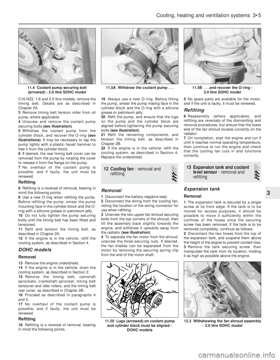
4Unscrew and remove the coolant pump
securing bolts (see illustration).
5Withdraw the coolant pump from the
cylinder block, and recover the O-ring (see
illustrations). It may be necessary to tap the
pump lightly with a plastic-faced hammer to
free it from the cylinder block.
6If desired, the rear timing belt cover can be
removed from the pump by rotating the cover
to release it from the flange on the pump.
7No overhaul of the coolant pump is
possible, and if faulty, the unit must be
renewed.
Refitting
8Refitting is a reversal of removal, bearing in
mind the following points.
9Use a new O-ring when refitting the pump.
Before refitting the pump, smear the pump
mounting face in the cylinder block and the O-
ring with a silicone grease or petroleum jelly.
10Do not fully tighten the pump securing
bolts until the timing belt has been fitted and
tensioned.
11Refit and tension the timing belt, as
described in Chapter 2A.
12If the engine is in the vehicle, refill the
cooling system, as described in Section 4.
DOHC models
Removal
13Remove the engine undershield.
14If the engine is in the vehicle, drain the
cooling system, as described in Section 2.
15Remove the timing belt, camshaft
sprockets, crankshaft sprocket, timing belt
tensioner and idler rollers, and the timing belt
rear cover, as described in Chapter 2B.
16Proceed as described in paragraphs 4
and 5.
17No overhaul of the coolant pump is
possible, and if faulty, the unit must be
renewed.
Refitting
18Refitting is a reversal of removal, bearing
in mind the following points.19Always use a new O-ring. Before fitting
the pump, smear the pump mating face in the
cylinder block and the O-ring with a silicone
grease or petroleum jelly.
20Refit the pump, and ensure that the lugs
on the pump and the cylinder block are
aligned before tightening the pump securing
bolts (see illustration).
21Refit the remaining components, and
tension the timing belt, as described in
Chapter 2B.
22If the engine is in the vehicle, refill the
cooling system, as described in Section 4.
Replace the undershield.
12Cooling fan - removal and
refitting
3
Removal
1Disconnect the battery negative lead.
2Disconnect the wiring from the cooling fan,
noting the location of the wiring connector for
use when refitting.
3Unscrew the two upper fan shroud securing
bolts from the top corners of the shroud, then
tilt the assembly back slightly towards the
engine, and withdraw it upwards away from
the radiator (see illustration).
4To separate the fan motor from the shroud,
unscrew the three securing nuts. If desired,
the fan blades can be separated from the
motor by removing the securing spring clip
from the end of the motor shaft.5No spare parts are available for the motor,
and if the unit is faulty, it must be renewed.
Refitting
6Reassembly (where applicable), and
refitting are reversals of the dismantling and
removal procedures, but ensure that the lower
end of the fan shroud locates correctly on the
radiator.
7On completion, start the engine and run it
until it reaches normal operating temperature,
then continue to run the engine and check
that the cooling fan cuts in and functions
correctly.
13Expansion tank and coolant
level sensor -removal and
refitting
3
Expansion tank
Removal
1The expansion tank is secured by a single
screw at its front edge. If the tank is to be
moved for access purposes, it should be
possible to move it sufficiently within the
confines of the hoses once the securing
screw has been removed. If the tank is to be
removed completely, continue as follows.
2Disconnect the two hoses from the top of
the expansion tank, and suspend them above
the height of the engine to prevent coolant loss.
3Remove the tank securing screw, then
manipulate the tank from its location, holding
it as high as possible above the engine.
Cooling, heating and ventilation systems 3•5
11.5B . . .and recover the O-ring -
2.0 litre SOHC model
12.3 Withdrawing the fan shroud assembly
- 2.0 litre SOHC model11.20 Lugs (arrowed) on coolant pump
and cylinder block must be aligned -
DOHC models
11.5A Withdraw the coolant pump . . .11.4 Coolant pump securing bolt
(arrowed) - 2.0 litre SOHC model
3
Page 240 of 525
REF
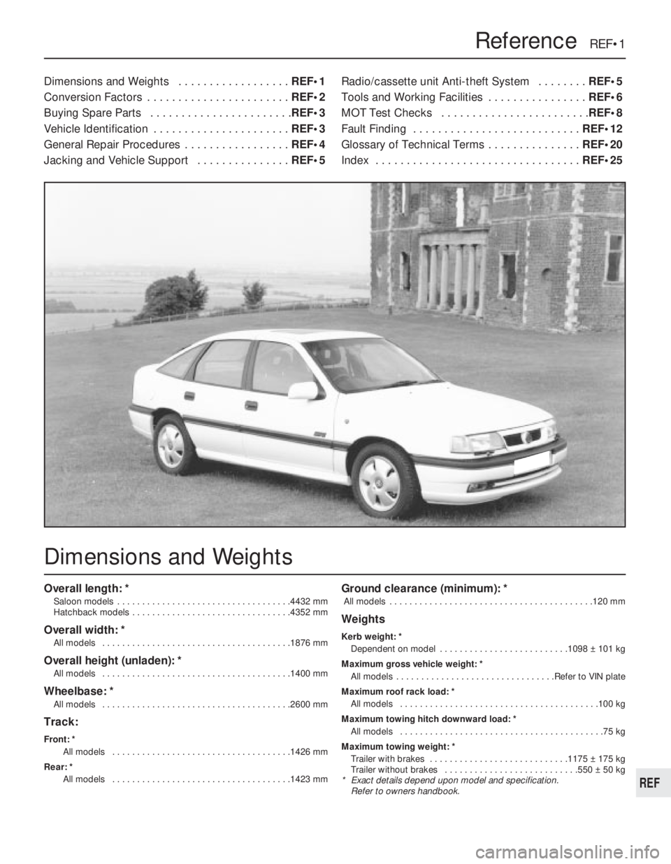
Overall length: *
Saloon models . . . . . . . . . . . . . . . . . . . . . . . . . . . . . . . . . . .4432 mm
Hatchback models . . . . . . . . . . . . . . . . . . . . . . . . . . . . . . . .4352 mm
Overall width: *
All models . . . . . . . . . . . . . . . . . . . . . . . . . . . . . . . . . . . . . .1876 mm
Overall height (unladen): *
All models . . . . . . . . . . . . . . . . . . . . . . . . . . . . . . . . . . . . . .1400 mm
Wheelbase: *
All models . . . . . . . . . . . . . . . . . . . . . . . . . . . . . . . . . . . . . .2600 mm
Track:
Front: *
All models . . . . . . . . . . . . . . . . . . . . . . . . . . . . . . . . . . . .1426 mm
Rear: *
All models . . . . . . . . . . . . . . . . . . . . . . . . . . . . . . . . . . . .1423 mm
Ground clearance (minimum): *
All models . . . . . . . . . . . . . . . . . . . . . . . . . . . . . . . . . . . . . . . . .120 mm
Weights
Kerb weight: *
Dependent on model . . . . . . . . . . . . . . . . . . . . . . . . . .1098 ± 101 kg
Maximum gross vehicle weight: *
All models . . . . . . . . . . . . . . . . . . . . . . . . . . . . . . . .Refer to VIN plate
Maximum roof rack load: *
All models . . . . . . . . . . . . . . . . . . . . . . . . . . . . . . . . . . . . . . . .100 kg
Maximum towing hitch downward load: *
All models . . . . . . . . . . . . . . . . . . . . . . . . . . . . . . . . . . . . . . . . .75 kg
Maximum towing weight: *
Trailer with brakes . . . . . . . . . . . . . . . . . . . . . . . . . . . .1175 ± 175 kg
Trailer without brakes . . . . . . . . . . . . . . . . . . . . . . . . . . .550 ± 50 kg
* Exact details depend upon model and specification.
Refer to owners handbook.
Dimensions and Weights . . . . . . . . . . . . . . . . . .REF•1
Conversion Factors . . . . . . . . . . . . . . . . . . . . . . .REF•2
Buying Spare Parts . . . . . . . . . . . . . . . . . . . . . . .REF•3
Vehicle Identification . . . . . . . . . . . . . . . . . . . . . .REF•3
General Repair Procedures . . . . . . . . . . . . . . . . .REF•4
Jacking and Vehicle Support . . . . . . . . . . . . . . .REF•5Radio/cassette unit Anti-theft System . . . . . . . .REF•5
Tools and Working Facilities . . . . . . . . . . . . . . . .REF•6
MOT Test Checks . . . . . . . . . . . . . . . . . . . . . . . .REF•8
Fault Finding . . . . . . . . . . . . . . . . . . . . . . . . . . .REF•12
Glossary of Technical Terms . . . . . . . . . . . . . . .REF•20
Index . . . . . . . . . . . . . . . . . . . . . . . . . . . . . . . . .REF•25
Reference REF•1
Dimensions and Weights
Page 243 of 525

REF•4General Repair Procedures
Whenever servicing, repair or overhaul work
is carried out on the car or its components, it is
necessary to observe the following procedures
and instructions. This will assist in carrying out
the operation efficiently and to a professional
standard of workmanship.
Joint mating faces and gaskets
When separating components at their
mating faces, never insert screwdrivers or
similar implements into the joint between the
faces in order to prise them apart. This can
cause severe damage which results in oil
leaks, coolant leaks, etc upon reassembly.
Separation is usually achieved by tapping
along the joint with a soft-faced hammer in
order to break the seal. However, note that this
method may not be suitable where dowels are
used for component location.
Where a gasket is used between the mating
faces of two components, ensure that it is
renewed on reassembly, and fit it dry unless
otherwise stated in the repair procedure. Make
sure that the mating faces are clean and dry,
with all traces of old gasket removed. When
cleaning a joint face, use a tool which is not
likely to score or damage the face, and remove
any burrs or nicks with an oilstone or fine file.
Make sure that tapped holes are cleaned
with a pipe cleaner, and keep them free of
jointing compound, if this is being used, unless
specifically instructed otherwise.
Ensure that all orifices, channels or pipes
are clear, and blow through them, preferably
using compressed air.
Oil seals
Oil seals can be removed by levering them
out with a wide flat-bladed screwdriver or
similar implement. Alternatively, a number of
self-tapping screws may be screwed into the
seal, and these used as a purchase for pliers
or some similar device in order to pull the seal
free.
Whenever an oil seal is removed from its
working location, either individually or as part
of an assembly, it should be renewed.
The very fine sealing lip of the seal is easily
damaged, and will not seal if the surface it
contacts is not completely clean and free from
scratches, nicks or grooves.
Protect the lips of the seal from any surface
which may damage them in the course of
fitting. Use tape or a conical sleeve where
possible. Lubricate the seal lips with oil before
fitting and, on dual-lipped seals, fill the space
between the lips with grease.
Unless otherwise stated, oil seals must be
fitted with their sealing lips toward the
lubricant to be sealed.
Use a tubular drift or block of wood of the
appropriate size to install the seal and, if the
seal housing is shouldered, drive the seal
down to the shoulder. If the seal housing is
unshouldered, the seal should be fitted with its
face flush with the housing top face (unless
otherwise instructed).
Screw threads and fastenings
Seized nuts, bolts and screws are quite a
common occurrence where corrosion has set
in, and the use of penetrating oil or releasing
fluid will often overcome this problem if the
offending item is soaked for a while before
attempting to release it. The use of an impact
driver may also provide a means of releasing
such stubborn fastening devices, when used
in conjunction with the appropriate
screwdriver bit or socket. If none of these
methods works, it may be necessary to resort
to the careful application of heat, or the use of
a hacksaw or nut splitter device.
Studs are usually removed by locking two
nuts together on the threaded part, and then
using a spanner on the lower nut to unscrew
the stud. Studs or bolts which have broken off
below the surface of the component in which
they are mounted can sometimes be removed
using a proprietary stud extractor. Always
ensure that a blind tapped hole is completely
free from oil, grease, water or other fluid
before installing the bolt or stud. Failure to do
this could cause the housing to crack due to
the hydraulic action of the bolt or stud as it is
screwed in.
When tightening a castellated nut to accept
a split pin, tighten the nut to the specified
torque, where applicable, and then tighten
further to the next split pin hole. Never slacken
the nut to align the split pin hole, unless stated
in the repair procedure.
When checking or retightening a nut or bolt
to a specified torque setting, slacken the nut
or bolt by a quarter of a turn, and then
retighten to the specified setting. However,
this should not be attempted where angular
tightening has been used.
For some screw fastenings, notably cylinder
head bolts or nuts, torque wrench settings are
no longer specified for the latter stages of
tightening, “angle-tightening” being called up
instead. Typically, a fairly low torque wrench
setting will be applied to the bolts/nuts in
the correct sequence, followed by one or
more stages of tightening through specified
angles.
Locknuts, locktabs and washers
Any fastening which will rotate against a
component or housing in the course of
tightening should always have a washer
between it and the relevant component or
housing.
Spring or split washers should always be
renewed when they are used to lock a critical
component such as a big-end bearing
retaining bolt or nut. Locktabs which are
folded over to retain a nut or bolt should
always be renewed.
Self-locking nuts can be re-used in non-
critical areas, providing resistance can be felt
when the locking portion passes over the bolt
or stud thread. However, it should be noted
that self-locking stiffnuts tend to lose theireffectiveness after long periods of use, and in
such cases should be renewed as a matter of
course.
Split pins must always be replaced with new
ones of the correct size for the hole.
When thread-locking compound is found on
the threads of a fastener which is to be re-
used, it should be cleaned off with a wire
brush and solvent, and fresh compound
applied on reassembly.
Special tools
Some repair procedures in this manual
entail the use of special tools such as a press,
two or three-legged pullers, spring
compressors, etc. Wherever possible, suitable
readily-available alternatives to the
manufacturer’s special tools are described,
and are shown in use. Unless you are highly-
skilled and have a thorough understanding of
the procedures described, never attempt to
bypass the use of any special tool when the
procedure described specifies its use. Not
only is there a very great risk of personal injury,
but expensive damage could be caused to the
components involved.
Environmental considerations
When disposing of used engine oil, brake
fluid, antifreeze, etc, give due consideration to
any detrimental environmental effects. Do not,
for instance, pour any of the above liquids
down drains into the general sewage system,
or onto the ground to soak away. Many local
council refuse tips provide a facility for waste
oil disposal, as do some garages. If none of
these facilities are available, consult your local
Environmental Health Department for further
advice.
With the universal tightening-up of
legislation regarding the emission of
environmentally-harmful substances from
motor vehicles, most current vehicles have
tamperproof devices fitted to the main
adjustment points of the fuel system. These
devices are primarily designed to prevent
unqualified persons from adjusting the fuel/air
mixture, with the chance of a consequent
increase in toxic emissions. If such devices are
encountered during servicing or overhaul, they
should, wherever possible, be renewed or
refitted in accordance with the vehicle
manufacturer’s requirements or current
legislation.
Note: It is
antisocial and
illegal to dump
oil down the
drain. To find
the location of
your local oil
recycling
bank, call this
number free.