1988 OPEL CALIBRA power steering fluid
[x] Cancel search: power steering fluidPage 93 of 525
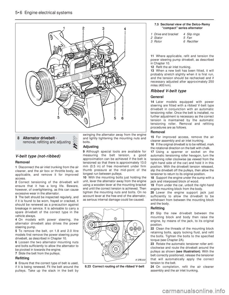
8Alternator drivebelt -
removal, refitting and adjusting
2
V-belt type (not-ribbed)
Removal
1Disconnect the air inlet trunking from the air
cleaner, and the air box or throttle body, as
applicable, and remove it for improved
access.
2Correct tensioning of the drivebelt will
ensure that it has a long life. Beware,
however, of overtightening, as this can cause
excessive wear in the alternator.
3The belt should be inspected regularly, and
if it is found to be worn, frayed or cracked, it
should be renewed as a precaution against
breakage in service. It is advisable to carry a
spare drivebelt of the correct type in the
vehicle always.
4On models with power steering, the
alternator drivebelt also drives the power
steering pump.
5To remove the belt, on 1.8 and 2.0 litre
models first remove the power steering pump
drivebelt, as described in Chapter 10.
6Loosen the two alternator mounting nuts
and bolts sufficiently to allow the alternator to
be pivoted in towards the engine.
7Slide the belt from the pulleys.
Refitting
8Ensure that the correct type of belt is used,
if it is being renewed. Fit the belt around the
pulleys. Take up the slack in the belt byswinging the alternator away from the engine
and lightly tightening the mounting nuts and
bolts.
Adjusting
9Although special tools are available for
measuring the belt tension, a good
approximation can be achieved if the belt is
tensioned so that there is approximately 13.0
mm (0.5 in) of free movement under firm
thumb pressure at the mid-point of the
longest run between pulleys.
10With the mounting bolts just holding the
unit, lever the alternator away from the engine
using a wooden lever at the mounting bracket
end until the correct tension is achieved. Then
tighten the mounting nuts and bolts. On no
account lever at the free end of the alternator,
as serious internal damage could be caused.11Where applicable, refit and tension the
power steering pump drivebelt, as described
in Chapter 10.
12Refit the air inlet trunking.
13When a new belt has been fitted, it will
probably stretch slightly when it is first run,
and the tension should be rechecked and if
necessary adjusted after approximately 250
miles (400 km).
Ribbed V-belt type
General
14Later models equipped with power
steering are fitted with a ribbed V-belt type
drivebelt in conjunction with an automatic
tensioning roller. Once the belt is installed, no
further adjustment is necessary as the correct
tension is maintained by the automatic
tensioning roller. Removal and refitting
procedures are as follows.
Removal
15For improved access, remove the air
cleaner assembly and air inlet trunking.
16If the original drivebelt is to be refitted, mark
the rotational direction on the belt with chalk.
17Using a spanner or socket on the
automatic tensioning roller hexagon, turn the
tensioning roller clockwise (as viewed from the
right-hand side of the car) and hold it in this
position. With the drivebelt tension released,
slip the drivebelt off the pulleys, then allow the
tensioner to return to its original position.
18Support the engine under the sump with a
jack and interposed block of wood.
19From under the car, unbolt the right-hand
engine mounting block from the body.
20Lower the engine support jack just
sufficiently to allow the drivebelt to be
withdrawn from between the mounting block
and the body.
Refitting
21Slip the new drivebelt between the
mounting block and body then raise the
engine, by means of the jack, to its original
position.
22Clean the threads of the mounting block
retaining bolts, apply locking fluid, and refit
the bolts. Tighten the bolts to the specified
torque (see Chapter 2A).
23Rotate the automatic tensioner roller anti-
clockwise and route the drivebelt around the
pulleys as shown (see illustration). With the
belt correctly positioned, release the tensioner
that will automatically apply the correct
tension to the belt.
24On completion, refit the air cleaner
assembly and the air inlet trunking.
5•6Engine electrical systems
7.5 Sectional view of the Delco-Remy
“compact” series alternator
1 Drive end bracket
2 Stator
3 Rotor4 Slip rings
5 Fan
6 Rectifier
8.23 Correct routing of the ribbed V-belt
Page 96 of 525

2When the starter switch is operated, current
flows from the battery to the solenoid that is
mounted on the starter body. The plunger in
the solenoid moves inwards, so causing a
centrally pivoted lever to push the drive pinion
into mesh with the starter ring gear. When the
solenoid plunger reaches the end of its travel,
it closes an internal contact and full starting
current flows to the starter field coils. The
armature is then able to rotate the crankshaft,
so starting the engine.
3A special freewheel clutch is fitted to the
starter driven pinion, so that when the engine
fires and starts to operate on its own it does
not drive the starter motor.
4When the starter switch is released, the
solenoid is de-energised, and a spring moves
the plunger back to its rest position. This
operates the pivoted lever to the withdraw the
drive pinion from engagement with the starter
ring.
13Starter motor - testing
3
Note: Refer to Section 3 before proceeding
Testing
1If the starter motor fails to turn the engine
when the switch is operated, and engine
seizure is not the problem, there are several
other possible reasons:
a)The battery is faulty
b)The electrical connections between the
switch, solenoid battery and starter motor
are somewhere failing to pass the
necessary current from the battery
through the starter to earth
c)The solenoid switch is faulty
d)The starter motor is mechanically or
electrically defective
e)The starter motor pinion and/or flywheel
ring gear is badly worn, and in need of
replacement
2To check the battery, switch on the
headlamps. If they dim after a few seconds,
then the battery is in a discharged state. If the
lamps glow brightly, operate the starter switch
and see what happens to the lamps. If theydim, then power is reaching the motor, but
failing to turn it. If the starter turns slowly, go
on to the next check.
3If, when the starter switch is operated, the
lamps stay bright, then insufficient power is
reaching the motor. Disconnect the battery
and the starter/solenoid power connections,
and the engine earth strap, then thoroughly
clean them and refit them. Smear petroleum
jelly around the battery connections to
prevent corrosion. Corroded connections are
the most frequent cause of electrical system
malfunctions.
4If the preceding checks and cleaning tasks
have been carried out without success, a
clicking noise will probably have been heard
each time the starter switch was operated.
This indicates that the solenoid switch was
operating, but it does not necessarily follow
that the main contacts were closing properly
(if no clicking has been heard from the
solenoid, it is certainly defective). The
solenoid can be checked by connecting a
voltmeter across the main cable connection
on the solenoid and earth. When the switch is
operated, these should be a reading on the
voltmeter. If there is no reading, the solenoid
unit is faulty, and should be renewed.
5If the starter motor operates, but does not
turn the engine, then it is likely that the starter
pinion and/or flywheel ring gear are badly
worn. If this is the case, the starter motor will
normally be noisy in operation.
6Finally, if it is established that the solenoid
is not faulty, and 12 volts are reaching the
starter, then the motor itself is faulty, and
should be removed for inspection.
14Starter motor - removal and
refitting
3
Note: Refer to Section 3 before proceeding
Removal
1Disconnect the battery negative lead.
2Apply the handbrake, then jack up the front
of the vehicle, and support securely on axle
stands (see “Jacking and Vehicle Support”)
positioned under the body side members.3On DOHC models, remove the engine
undershield, as described in Chapter 11.
4Note the wiring connections on the
solenoid, then disconnect them (see
illustration).
5Where applicable, unscrew the bolt
securing the exhaust bracket and the starter
motor mounting bracket to the cylinder block
(see illustration).
6Unscrew the two starter motor mounting
bolts. Note that the top bolt on some models
are fitted from the transmission side, and
secures a wiring harness bracket (see
illustration).
7Withdraw the starter motor.
Refitting
8Refitting is a reversal of removal, but where
applicable, ensure that the wiring harness
bracket is in place on the top mounting bolt,
and tighten all bolts to the specified torque.
15Starter motor - overhaul
5
If the starter motor is thought to be suspect,
it should be removed from the vehicle and
taken to an auto-electrician for testing. Most
auto-electricians will be able to supply and fit
brushes at a reasonable cost. However, check
on the cost of repairs before continuing as it
may prove more economical to obtain a new
or exchange motor.
16Ignition coil - removal, testing
and refitting
3
Note: Refer to Section 3 before proceeding.
An ohmmeter will be required to test the coil
Removal
1The ignition coil is either a cylindrical metal
canister or a moulded plastic unit. It is
clamped or bolted to the left-hand inner wing
panel, near the suspension strut top mounting
(under the power steering fluid reservoir, on
Engine electrical systems 5•9
14.6 Starter motor securing bolts
(arrowed) - 1.6 litre model
(engine removed)14.5 Starter motor mounting
bracket/exhaust bracket securing bolt
(arrowed) - 1.6 litre model14.4 Starter motor and solenoid viewed
from underneath the vehicle. Solenoid
wiring connections arrowed
5
Page 97 of 525
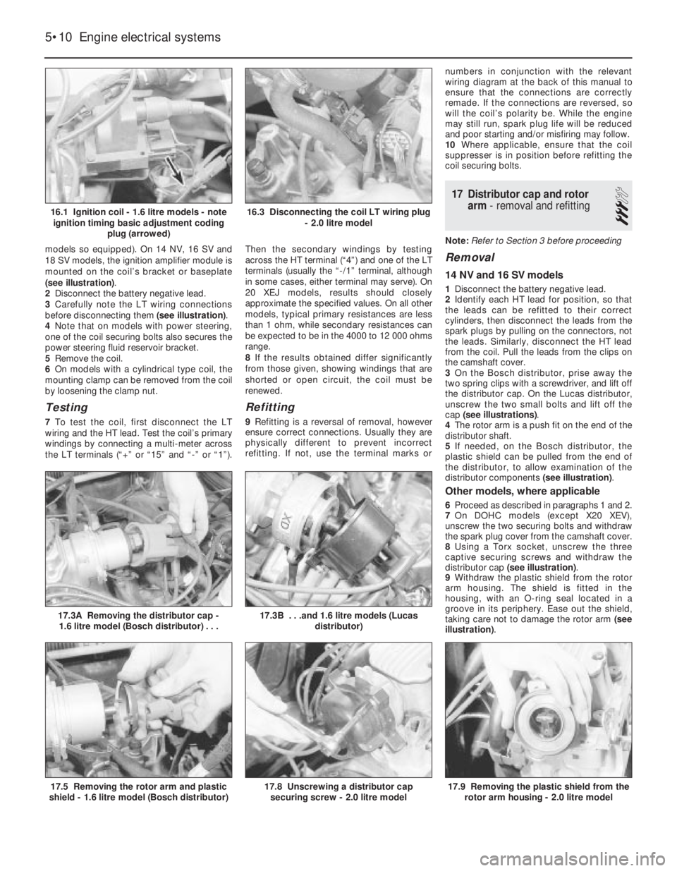
models so equipped). On 14 NV, 16 SV and
18 SV models, the ignition amplifier module is
mounted on the coil’s bracket or baseplate
(see illustration).
2Disconnect the battery negative lead.
3Carefully note the LT wiring connections
before disconnecting them (see illustration).
4Note that on models with power steering,
one of the coil securing bolts also secures the
power steering fluid reservoir bracket.
5Remove the coil.
6On models with a cylindrical type coil, the
mounting clamp can be removed from the coil
by loosening the clamp nut.
Testing
7To test the coil, first disconnect the LT
wiring and the HT lead. Test the coil’s primary
windings by connecting a multi-meter across
the LT terminals (“+” or “15” and “-” or “1”).Then the secondary windings by testing
across the HT terminal (“4”) and one of the LT
terminals (usually the “-/1” terminal, although
in some cases, either terminal may serve). On
20 XEJ models, results should closely
approximate the specified values. On all other
models, typical primary resistances are less
than 1 ohm, while secondary resistances can
be expected to be in the 4000 to 12 000 ohms
range.
8If the results obtained differ significantly
from those given, showing windings that are
shorted or open circuit, the coil must be
renewed.
Refitting
9Refitting is a reversal of removal, however
ensure correct connections. Usually they are
physically different to prevent incorrect
refitting. If not, use the terminal marks ornumbers in conjunction with the relevant
wiring diagram at the back of this manual to
ensure that the connections are correctly
remade. If the connections are reversed, so
will the coil’s polarity be. While the engine
may still run, spark plug life will be reduced
and poor starting and/or misfiring may follow.
10Where applicable, ensure that the coil
suppresser is in position before refitting the
coil securing bolts.
17Distributor cap and rotor
arm -removal and refitting
3
Note: Refer to Section 3 before proceeding
Removal
14 NV and 16 SV models
1Disconnect the battery negative lead.
2Identify each HT lead for position, so that
the leads can be refitted to their correct
cylinders, then disconnect the leads from the
spark plugs by pulling on the connectors, not
the leads. Similarly, disconnect the HT lead
from the coil. Pull the leads from the clips on
the camshaft cover.
3On the Bosch distributor, prise away the
two spring clips with a screwdriver, and lift off
the distributor cap. On the Lucas distributor,
unscrew the two small bolts and lift off the
cap (see illustrations).
4The rotor arm is a push fit on the end of the
distributor shaft.
5If needed, on the Bosch distributor, the
plastic shield can be pulled from the end of
the distributor, to allow examination of the
distributor components (see illustration).
Other models, where applicable
6Proceed as described in paragraphs 1 and 2.
7On DOHC models (except X20 XEV),
unscrew the two securing bolts and withdraw
the spark plug cover from the camshaft cover.
8Using a Torx socket, unscrew the three
captive securing screws and withdraw the
distributor cap (see illustration).
9Withdraw the plastic shield from the rotor
arm housing. The shield is fitted in the
housing, with an O-ring seal located in a
groove in its periphery. Ease out the shield,
taking care not to damage the rotor arm (see
illustration).
5•10Engine electrical systems
16.1 Ignition coil - 1.6 litre models - note
ignition timing basic adjustment coding
plug (arrowed)
17.3A Removing the distributor cap -
1.6 litre model (Bosch distributor) . . .
17.9 Removing the plastic shield from the
rotor arm housing - 2.0 litre model17.8 Unscrewing a distributor cap
securing screw - 2.0 litre model17.5 Removing the rotor arm and plastic
shield - 1.6 litre model (Bosch distributor)
17.3B . . .and 1.6 litre models (Lucas
distributor)
16.3 Disconnecting the coil LT wiring plug
- 2.0 litre model
Page 149 of 525
8Disconnect the battery negative lead.
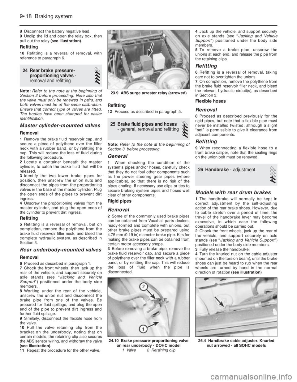
9Unclip the lid and open the relay box, then
pull out the relay (see illustration).
Refitting
10Refitting is a reversal of removal, with
reference to paragraph 6.
24Rear brake pressure-
proportioning valves -
removal and refitting
4
Note: Refer to the note at the beginning of
Section 3 before proceeding. Note also that
the valve must only be renewed in pairs, and
both valves must be of the same calibration.
Ensure that correct type of valves are fitted.
The bodies have been stamped for easier
identification.
Master cylinder-mounted valves
Removal
1Remove the brake fluid reservoir cap, and
secure a piece of polythene over the filler
neck with a rubber band, or by refitting the
cap. This will reduce the loss of fluid during
the following procedure.
2Locate a container beneath the master
cylinder, to catch the brake fluid that will be
released.
3Identify the two lower brake pipes for
position, then unscrew the union nuts and
disconnect the pipes from the proportioning
valves in the base of the master cylinder. Plug
the open ends of the pipes to prevent dirt
ingress.
4Unscrew the proportioning valves from the
master cylinder, and plug the open ends of
the cylinder to prevent dirt ingress.
Refitting
5Refitting is a reversal of removal, but on
completion, remove the polythene from the
brake fluid reservoir filler neck, and bleed the
complete hydraulic system, as described in
Section 3.
Rear underbody-mounted valves
Removal
6Proceed as described in paragraph 1.
7Chock the front wheels, then jack up the
rear of the vehicle, and support securely on
axle stands (see “Jacking and Vehicle
Support”) positioned under the body side
members.
8Working under the rear of the vehicle,
unscrew the union nut and disconnect the
brake pipe from one of the valves. Be
prepared for fluid spillage, and plug the open
end of the pipe to prevent dirt ingress and
further fluid spillage.
9Similarly, disconnect the flexible hose from
the valve.
10Pull the valve retaining clip from the
bracket on the underbody, noting that on
certain models, the retaining clip also secures
the ABS sensor wiring, and withdraw the valve
(see illustration).
11Repeat the procedure for the other valve.
Refitting
12Proceed as described in paragraph 5.
25Brake fluid pipes and hoses
- general, removal and refitting
4
Note: Refer to the note at the beginning of
Section 3, before proceeding.
General
1When checking the condition of the
system’s pipes and/or hoses, carefully check
that they do not foul other components such
as the power steering gear pipes (where
applicable), so that there is no risk of the
pipes chafing. If necessary use clips or ties to
secure braking system pipes and hoses well
clear of other components.
Rigid pipes
Removal
2Some of the commonly used brake pipes
can be obtained from Vauxhall parts dealers,
ready-formed and complete with unions, but
other brake pipes must be prepared using
4.75 mm (0.19 in) diameter brake pipe. Kits for
making the brake pipes can be obtained from
certain motor accessory shops.
3Before removing a brake pipe, remove the
brake fluid reservoir cap, and secure a piece
of polythene over the filler neck with a rubber
band, or by refitting the cap. This will reduce
the loss of fluid when the pipe is
disconnected.4Jack up the vehicle, and support securely
on axle stands (see “Jacking and Vehicle
Support”) positioned under the body side
members.
5To remove a brake pipe, unscrew the
unions at each end, and release the pipe from
the retaining clips.
Refitting
6Refitting is a reversal of removal, taking
care not to overtighten the unions.
7On completion, remove the polythene from
the brake fluid reservoir filler neck, and bleed
the relevant hydraulic circuit(s), as described
in Section 3.
Flexible hoses
Removal
8Proceed as described previously for the
rigid pipes, but note that a flexible pipe must
never be installed twisted, although a slight
“set” is permissible to give it clearance from
adjacent components.
Refitting
9When reconnecting a flexible hose to a
front brake caliper, note that the sealing rings
on the union bolt must be renewed.
26Handbrake - adjustment
2
Models with rear drum brakes
1The handbrake will normally be kept in
correct adjustment by the self-adjusting
action of the rear brake shoes. However, due
to cable stretch over a period of time, the
travel of the handbrake lever may become
excessive, in which case the following
operations should be carried out.
2Chock the front wheels, jack up the rear of
the vehicle, and support securely on axle
stands (see “Jacking and Vehicle Support”)
positioned under the body side members.
3Fully release the handbrake.
4Turn the knurled nut on the cable adjuster
(mounted on the torsion beam), until the brake
shoes can just be heard to rub when the rear
wheels are turned by hand in the normal
direction of rotation (see illustration).
9•18Braking system
23.9 ABS surge arrester relay (arrowed)
26.4 Handbrake cable adjuster. Knurled
nut arrowed - all SOHC models24.10 Brake pressure-proportioning valve
on rear underbody - DOHC model
1 Valve 2 Retaining clip
Page 172 of 525
1
Chapter 1
Routine maintenance and servicing
Air cleaner element - renewal . . . . . . . . . . . . . . . . . . . . . . . . . . . . . . .27
Air inlet temperature control check . . . . . . . . . . . . . . . . . . . . . . . . . .28
Alternator V-belt check . . . . . . . . . . . . . . . . . . . . . . . . . . . . . . . . . . . .22
Automatic transmission check . . . . . . . . . . . . . . . . . . . . . . . . . . . . . .34
Automatic transmission fluid level check . . . . . . . . . . . . . . . . . . . . . . .7
Automatic transmission fluid renewal . . . . . . . . . . . . . . . . . . . . . . . . .38
Bodywork check . . . . . . . . . . . . . . . . . . . . . . . . . . . . . . . . . . . . . . . . .20
Brake fluid renewal . . . . . . . . . . . . . . . . . . . . . . . . . . . . . . . . . . . . . . .14
Brake pad check . . . . . . . . . . . . . . . . . . . . . . . . . . . . . . . . . . . . . . . . .15
Brake shoe check . . . . . . . . . . . . . . . . . . . . . . . . . . . . . . . . . . . . . . . .35
Clutch cable check . . . . . . . . . . . . . . . . . . . . . . . . . . . . . . . . . . . . . . .32
Coolant renewal . . . . . . . . . . . . . . . . . . . . . . . . . . . . . . . . . . . . . . . . .26
Distributor and HT lead check . . . . . . . . . . . . . . . . . . . . . . . . . . . . . .31
Door lock key battery - replacement . . . . . . . . . . . . . . . . . . . . . . . . .24
Driveshaft gaiter check . . . . . . . . . . . . . . . . . . . . . . . . . . . . . . . . . . . . .6
Engine oil and filter - renewal . . . . . . . . . . . . . . . . . . . . . . . . . . . . . . . .3
Exhaust system check . . . . . . . . . . . . . . . . . . . . . . . . . . . . . . . . . . . .11
Fuel filter renewal . . . . . . . . . . . . . . . . . . . . . . . . . . . . . . . . . . . . . . . .29
Handbrake linkage check . . . . . . . . . . . . . . . . . . . . . . . . . . . . . . . . . .16Headlamp alignment . . . . . . . . . . . . . . . . . . . . . . . . . . . . . . . . . . . . . .23
Hose and fluid leak check . . . . . . . . . . . . . . . . . . . . . . . . . . . . . . . . . .4
Idle speed and mixture - adjustment . . . . . . . . . . . . . . . . . . . . . . . . . .9
Ignition timing . . . . . . . . . . . . . . . . . . . . . . . . . . . . . . . . . . . . . . . . . . .13
Intensive maintenance . . . . . . . . . . . . . . . . . . . . . . . . . . . . . . . . . . . . .2
Introduction . . . . . . . . . . . . . . . . . . . . . . . . . . . . . . . . . . . . . . . . . . . . .1
Lock and hinge check . . . . . . . . . . . . . . . . . . . . . . . . . . . . . . . . . . . .21
Manual transmission fluid check . . . . . . . . . . . . . . . . . . . . . . . . . . . .33
Power steering fluid check . . . . . . . . . . . . . . . . . . . . . . . . . . . . . . . . .17
Power steering pump drivebelt check . . . . . . . . . . . . . . . . . . . . . . . .18
Radiator inspection and cleaning . . . . . . . . . . . . . . . . . . . . . . . . . . . . .8
Rear suspension level control system check . . . . . . . . . . . . . . . . . . .19
Road test . . . . . . . . . . . . . . . . . . . . . . . . . . . . . . . . . . . . . . . . . . . . . .25
Spark plug renewal (SOHC) . . . . . . . . . . . . . . . . . . . . . . . . . . . . . . . .30
Spark plug renewal (DOHC) . . . . . . . . . . . . . . . . . . . . . . . . . . . . . . . .37
Steering and suspension check . . . . . . . . . . . . . . . . . . . . . . . . . . . . . .5
Throttle linkage maintenance . . . . . . . . . . . . . . . . . . . . . . . . . . . . . . .10
Timing belt renewal . . . . . . . . . . . . . . . . . . . . . . . . . . . . . . . . . . . . . . .36
Wiring check . . . . . . . . . . . . . . . . . . . . . . . . . . . . . . . . . . . . . . . . . . . .12
1•1
Contents
Easy,suitable for
novice with little
experienceFairly easy,suitable
for beginner with
some experienceFairly difficult,
suitable for competent
DIY mechanic
Difficult,suitable for
experienced DIY
mechanicVery difficult,
suitable for expert DIY
or professional
Degrees of difficulty
54321
Page 173 of 525
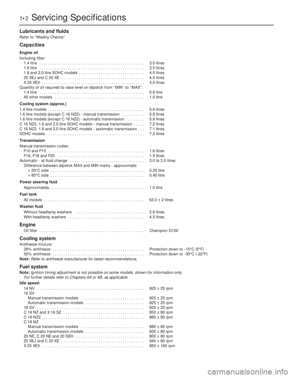
Lubricants and fluids
Refer to “Weekly Checks”
Capacities
Engine oil
Including filter:
1.4 litre . . . . . . . . . . . . . . . . . . . . . . . . . . . . . . . . . . . . . . . . . . . . . . . .3.0 litres
1.6 litre . . . . . . . . . . . . . . . . . . . . . . . . . . . . . . . . . . . . . . . . . . . . . . . .3.5 litres
1.8 and 2.0 litre SOHC models . . . . . . . . . . . . . . . . . . . . . . . . . . . . . .4.0 litres
20 XEJ and C 20 XE . . . . . . . . . . . . . . . . . . . . . . . . . . . . . . . . . . . . . .4.5 litres
X 20 XEV . . . . . . . . . . . . . . . . . . . . . . . . . . . . . . . . . . . . . . . . . . . . . . .4.0 litres
Quantity of oil required to raise level on dipstick from “MIN” to “MAX”:
1.4 litre . . . . . . . . . . . . . . . . . . . . . . . . . . . . . . . . . . . . . . . . . . . . . . . .0.8 litre
All other models . . . . . . . . . . . . . . . . . . . . . . . . . . . . . . . . . . . . . . . . .1.0 litre
Cooling system (approx.)
1.4 litre models . . . . . . . . . . . . . . . . . . . . . . . . . . . . . . . . . . . . . . . . . . . .5.6 litres
1.6 litre models (except C 16 NZ2) - manual transmission . . . . . . . . . .5.8 litres
1.6 litre models (except C 16 NZ2) - automatic transmission . . . . . . . .5.6 litres
C 16 NZ2, 1.8 and 2.0 litre SOHC models - manual transmission . . . . .7.2 litres
C 16 NZ2, 1.8 and 2.0 litre SOHC models - automatic transmission . . .7.1 litres
DOHC models . . . . . . . . . . . . . . . . . . . . . . . . . . . . . . . . . . . . . . . . . . . . .7.2 litres
Transmission
Manual transmission codes:
F10 and F13 . . . . . . . . . . . . . . . . . . . . . . . . . . . . . . . . . . . . . . . . . . . .1.6 litres
F16, F18 and F20 . . . . . . . . . . . . . . . . . . . . . . . . . . . . . . . . . . . . . . . .1.9 litres
Automatic - at fluid change . . . . . . . . . . . . . . . . . . . . . . . . . . . . . . . . . .3.0 to 3.5 litres
Difference between dipstick MAX and MIN marks -approximate:
+ 20°C side . . . . . . . . . . . . . . . . . . . . . . . . . . . . . . . . . . . . . . . . . . .0.25 litre
+ 80°C side . . . . . . . . . . . . . . . . . . . . . . . . . . . . . . . . . . . . . . . . . . .0.40 litre
Power steering fluid
Approximately . . . . . . . . . . . . . . . . . . . . . . . . . . . . . . . . . . . . . . . . . . .1.0 litre
Fuel tank
All models . . . . . . . . . . . . . . . . . . . . . . . . . . . . . . . . . . . . . . . . . . . . . .63.0 ±2 litres
Washer fluid
Without headlamp washers . . . . . . . . . . . . . . . . . . . . . . . . . . . . . . . .2.6 litres
With headlamp washers . . . . . . . . . . . . . . . . . . . . . . . . . . . . . . . . . . .4.5 litres
Engine
Oil filter . . . . . . . . . . . . . . . . . . . . . . . . . . . . . . . . . . . . . . . . . . . . . . . .Champion G102
Cooling system
Antifreeze mixture:
28% antifreeze . . . . . . . . . . . . . . . . . . . . . . . . . . . . . . . . . . . . . . . . . .Protection down to -15°C (5°F)
50% antifreeze . . . . . . . . . . . . . . . . . . . . . . . . . . . . . . . . . . . . . . . . . .Protection down to -30°C (-22°F)
Note:
Refer to antifreeze manufacturer for latest recommendations.
Fuel system
Note:Ignition timing adjustment is not possible on some models, shown for information only.
For further details refer to Chapters 4A or 4B, as applicable.
Idle speed:
14 NV . . . . . . . . . . . . . . . . . . . . . . . . . . . . . . . . . . . . . . . . . . . . . . . . .925 ±25 rpm
16 SV
Manual transmission models . . . . . . . . . . . . . . . . . . . . . . . . . . . . .925 ±25 rpm
Automatic transmission models . . . . . . . . . . . . . . . . . . . . . . . . . . .825 ±25 rpm
18 SV . . . . . . . . . . . . . . . . . . . . . . . . . . . . . . . . . . . . . . . . . . . . . . . . . .925 ±25 rpm
C 16 NZ and X 16 SZ . . . . . . . . . . . . . . . . . . . . . . . . . . . . . . . . . . . . .850 ±80 rpm
C 16 NZ2 . . . . . . . . . . . . . . . . . . . . . . . . . . . . . . . . . . . . . . . . . . . . . . .880 ±80 rpm
C 18 NZ
Manual transmission models . . . . . . . . . . . . . . . . . . . . . . . . . . . . .880 ±80 rpm
Automatic transmission models . . . . . . . . . . . . . . . . . . . . . . . . . . .830 ±80 rpm
20 NE, C 20 NE and 20 SEH . . . . . . . . . . . . . . . . . . . . . . . . . . . . . . . .800 ±80 rpm
20 XEJ and C 20 XE . . . . . . . . . . . . . . . . . . . . . . . . . . . . . . . . . . . . . .940 ±80 rpm
X 20 XEV . . . . . . . . . . . . . . . . . . . . . . . . . . . . . . . . . . . . . . . . . . . . . . .850 ±160 rpm
1•2Servicing Specifications
Page 175 of 525
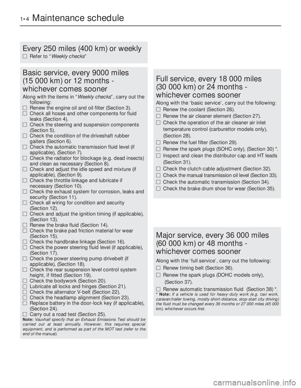
1•4Maintenance schedule
Every 250 miles (400 km) or weekly
MRefer to “Weekly checks”
Basic service, every 9000 miles
(15 000 km) or 12 months -
whichever comes sooner
Along with the items in “Weekly checks”, carry out the
following:
MRenew the engine oil and oil filter (Section 3).
MCheck all hoses and other components for fluid
leaks (Section 4).
MCheck the steering and suspension components
(Section 5).
MCheck the condition of the driveshaft rubber
gaiters (Section 6).
MCheck the automatic transmission fluid level (if
applicable), (Section 7).
MCheck the radiator for blockage (e.g. dead insects)
and clean as necessary (Section 8).
MCheck and adjust the idle speed and mixture (if
applicable), (Section 9).
MCheck the throttle linkage and lubricate if
necessary (Section 10).
MCheck the exhaust system for corrosion, leaks and
security (Section 11).
MCheck all wiring for condition and security
(Section 12).
MCheck and adjust the ignition timing (if applicable),
(Section 13).
MRenew the brake fluid (Section 14).
MCheck the brake pad friction material for wear
(Section 15).
MCheck the handbrake linkage (Section 16).
MCheck the power steering fluid level (if applicable),
(Section 17).
MCheck the power steering pump drivebelt (if
applicable), (Section 18).
MCheck the rear suspension level control system
height, if fitted (Section 19).
MCheck the bodywork (Section 20).
MLubricate all locks and hinges (Section 21).
MCheck the alternator V-belt (Section 22).
MCheck the headlamp alignment (Section 23).
MReplace battery in the door-lock key (if applicable),
(Section 24).
MCarry out a road test (Section 25).
Note: Vauxhall specify that an Exhaust Emissions Test should be
carried out at least annually. However, this requires special
equipment, and is performed as part of the MOT test (refer to the
end of the manual).
Full service, every 18 000 miles
(30 000 km) or 24 months -
whichever comes sooner
Along with the ‘basic service’, carry out the following:
MRenew the coolant (Section 26).
MRenew the air cleaner element (Section 27).
MCheck the operation of the air cleaner air inlet
temperature control (carburettor models only),
(Section 28).
MRenew the fuel filter (Section 29).
MRenew the spark plugs (SOHC only), (Section 30) *.
MInspect and clean the distributor cap and HT leads
(Section 31).
MCheck the clutch cable adjustment (Section 32).
MCheck the manual transmission oil level (Section 33).
MCheck the automatic transmission (Section 34).
MCheck the brake drum shoe for wear (Section 35).
Major service, every 36 000 miles
(60 000 km) or 48 months -
whichever comes sooner
Along with the ‘full service’, carry out the following:
MRenew timing belt (Section 36).
MRenew the spark plugs (DOHC models only),
(Section 37).
MRenew automatic transmission fluid (Section 38) *.
* Note: If a vehicle is used for heavy-duty work (e.g. taxi work,
caravan/trailer towing, mostly short-distance, stop-start city driving)
the fluid must be changed every 36 months or 27 000 miles (45 000
km), whichever occurs first.
Page 177 of 525
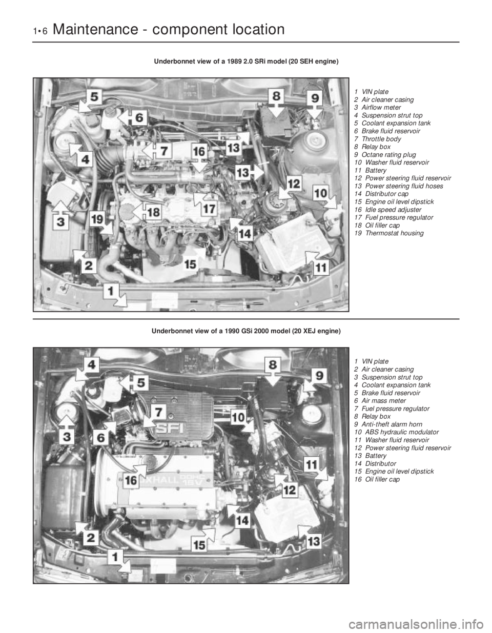
1•6Maintenance - component location
Underbonnet view of a 1989 2.0 SRi model (20 SEH engine)
1 VIN plate
2 Air cleaner casing
3 Airflow meter
4 Suspension strut top
5 Coolant expansion tank
6 Brake fluid reservoir
7 Throttle body
8 Relay box
9 Octane rating plug
10 Washer fluid reservoir
11 Battery
12 Power steering fluid reservoir
13 Power steering fluid hoses
14 Distributor cap
15 Engine oil level dipstick
16 Idle speed adjuster
17 Fuel pressure regulator
18 Oil filler cap
19 Thermostat housing
Underbonnet view of a 1990 GSi 2000 model (20 XEJ engine)
1 VIN plate
2 Air cleaner casing
3 Suspension strut top
4 Coolant expansion tank
5 Brake fluid reservoir
6 Air mass meter
7 Fuel pressure regulator
8 Relay box
9 Anti-theft alarm horn
10 ABS hydraulic modulator
11 Washer fluid reservoir
12 Power steering fluid reservoir
13 Battery
14 Distributor
15 Engine oil level dipstick
16 Oil filler cap