1987 SUZUKI GRAND VITARA oil filter
[x] Cancel search: oil filterPage 62 of 962
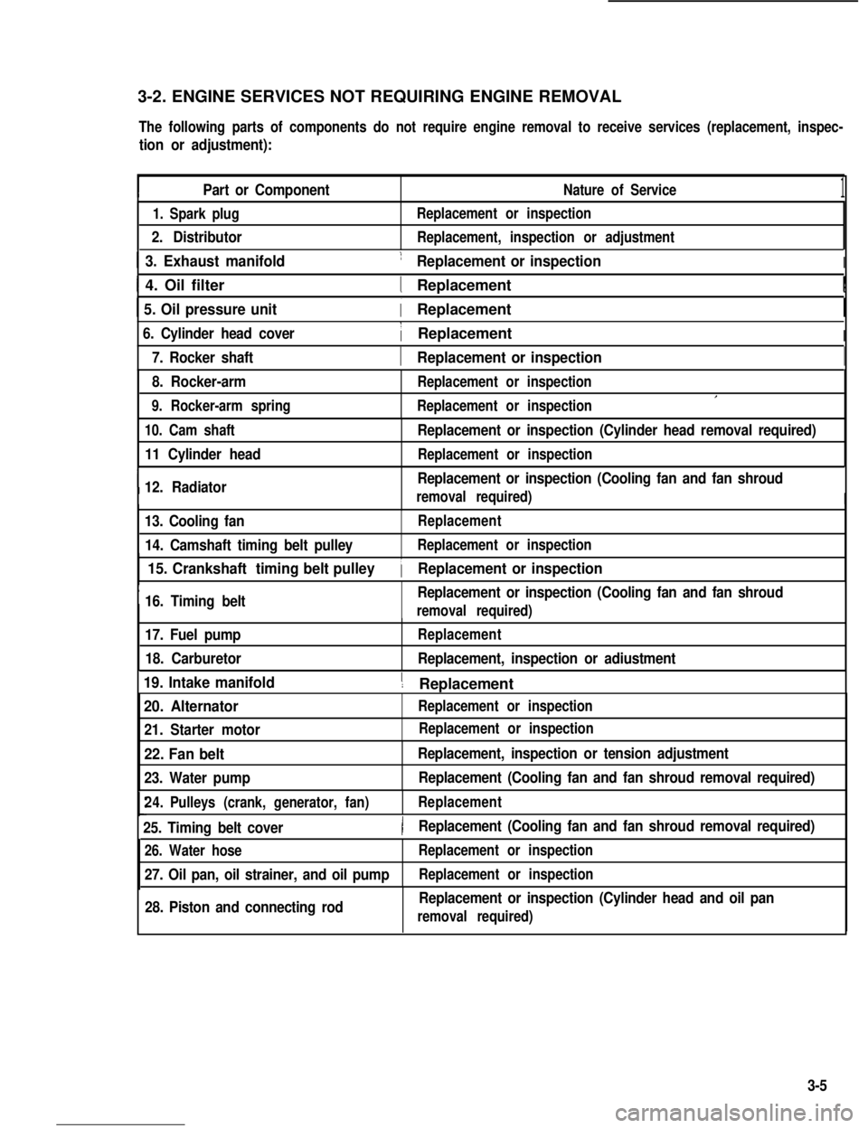
3-2. ENGINE SERVICES NOT REQUIRING ENGINE REMOVAL
The following parts of components do not require engine removal to receive services (replacement, inspec-
tion or adjustment):
Part or ComponentNature of Service1
1. Spark plug
2. Distributor
Replacement or inspection
Replacement, inspection or adjustment
1 3. Exhaust manifold1 Replacement or inspectionI
I 4. Oil filter1 ReplacementI
1 5. Oil pressure unit( Replacement
6. Cylinder head cover1 ReplacementI
I7. Rocker shaft1 Replacement or inspectionI
8. Rocker-arm
9. Rocker-arm spring
Replacement or inspection
Replacement or inspectionI
10. Cam shaft
11 Cylinder head
I12. Radiator
Replacement or inspection (Cylinder head removal required)
Replacement or inspection
Replacement or inspection (Cooling fan and fan shroud
removal required)I
13. Cooling fan
14. Camshaft timing belt pulley
Replacement
Replacement or inspection
I
15. Crankshaft timing belt pulley
16. Timing beltReplacement or inspection (Cooling fan and fan shroud
1 Replacement or inspection
removal required)
17. Fuel pump
18. Carburetor
Replacement
Replacement, inspection or adiustment
19. Intake manifold1 ReplacementI
20. Alternator
21. Starter motor
Replacement or inspection
22. Fan belt
23. Water pump
Replacement, inspection or tension adjustment
Replacement (Cooling fan and fan shroud removal required)
24.Pulleys (crank, generator, fan)Replacement
25. Timing belt cover)Replacement (Cooling fan and fan shroud removal required)
26. Water hose
27. Oil pan, oil strainer, and oil pump
Replacement or inspection
Replacement or inspection
28. Piston and connecting rodReplacement or inspection (Cylinder head and oil pan
removal required)
Replacement or inspection
3-5
Page 69 of 962
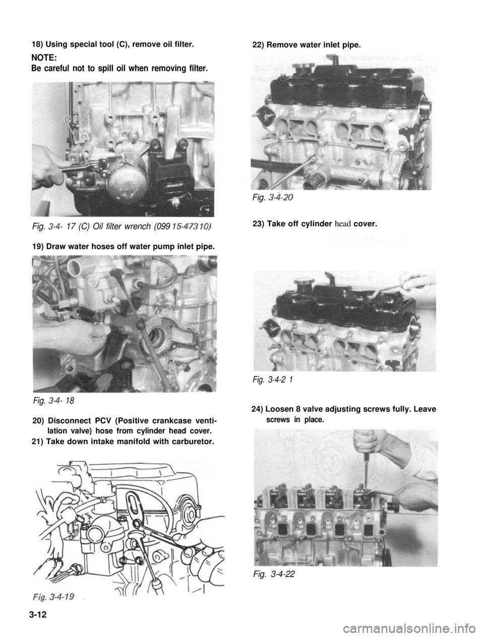
18) Using special tool (C), remove oil filter.
NOTE:
Be careful not to spill oil when removing filter.
22) Remove water inlet pipe.
Fig. 3-4- 17 (C) Oil filter wrench (099 15-473 10)
19) Draw water hoses off water pump inlet pipe.
Fig. 3-4-2 1
Fig. 3-4- 18
20) Disconnect PCV (Positive crankcase venti-
lation valve) hose from cylinder head cover.
21) Take down intake manifold with carburetor.
Fig. 3-4120
23) Take off cylinder head cover.
24) Loosen 8 valve adjusting screws fully. Leave
screws in place.
Fig. 3-4-22
3-12
Page 104 of 962
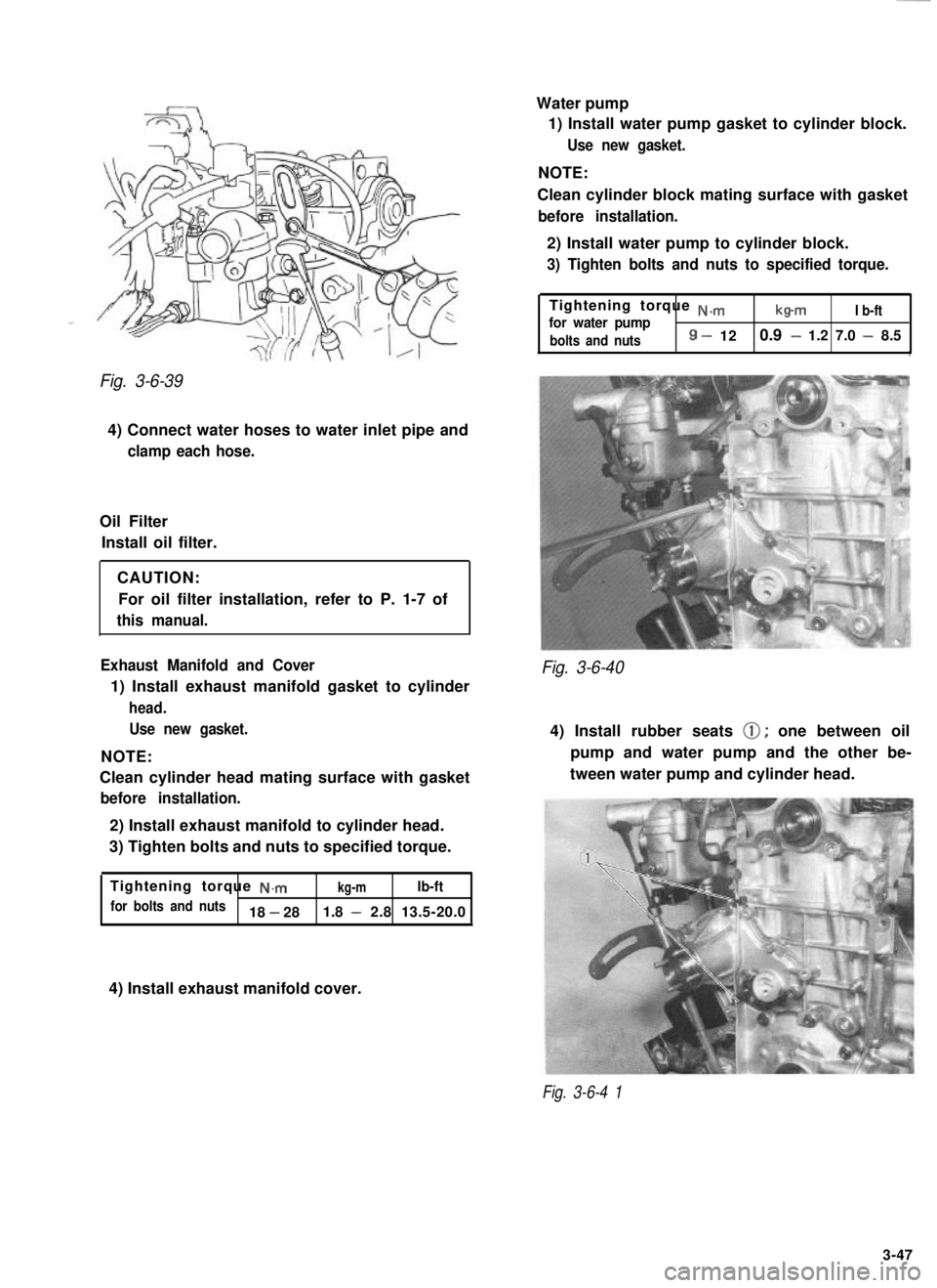
Fig. 3-6-39
4) Connect water hoses to water inlet pipe and
clamp each hose.
Oil FilterInstall oil filter.
CAUTION:For oil filter installation, refer to P. 1-7 of
this manual.
Exhaust Manifold and Cover
1) Install exhaust manifold gasket to cylinder
head. Use new gasket.
NOTE:
Clean cylinder head mating surface with gasket
before installation.
2) Install exhaust manifold to cylinder head.
3) Tighten bolts and nuts to specified torque.
Tightening torque
N.mkg-mlb-ft
for bolts and nuts18 - 28 1.8 - 2.8 13.5-20.0 Water pump
1) Install water pump gasket to cylinder block.
Use new gasket.
NOTE:
Clean cylinder block mating surface with gasket
before installation.
2) Install water pump to cylinder block.
3) Tighten bolts and nuts to specified torque.
Tightening torque N.m
for water pumpb-mI b-ft
bolts and nuts
8 - 12 0.9 - 1.2 7.0 - 8.5,
Fig. 3-6-40
4) Install rubber seats 0; one between oil
pump and water pump and the other be-
tween water pump and cylinder head.
4) Install exhaust manifold cover.
Fig. 3-6-4 1
3-47
Page 111 of 962
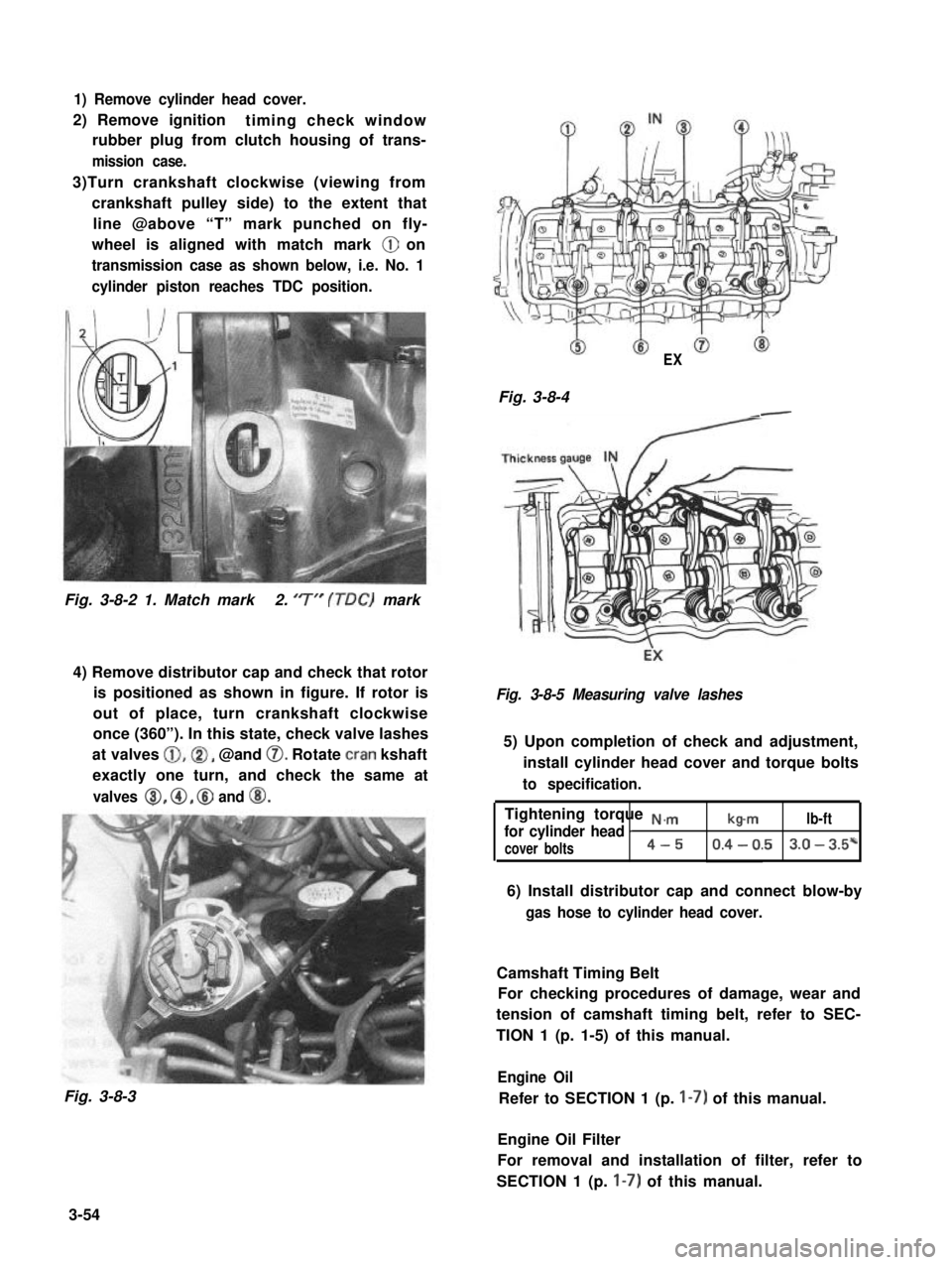
1) Remove cylinder head cover.
2) Remove ignitiontiming check window
rubber plug from clutch housing of trans-
mission case.
3)Turn crankshaft clockwise (viewing from
crankshaft pulley side) to the extent that
line @above “T” mark punched on fly-
wheel is aligned with match mark @ on
transmission case as shown below, i.e. No. 1
cylinder piston reaches TDC position.
Fig. 3-8-2 1. Match mark2. ‘7” (TDC) mark
4) Remove distributor cap and check that rotor
is positioned as shown in figure. If rotor is
out of place, turn crankshaft clockwise
once (360”). In this state, check valve lashes
at valves @,@I, @and 0. Rotate cran kshaft
exactly one turn, and check the same at
valves 8, @, @ and @I.
Fig. 3-8-3
EX
Fig. 3-8-4-
Fig. 3-8-5 Measuring valve lashes
5) Upon completion of check and adjustment,
install cylinder head cover and torque bolts
to specification.
Tightening torque N.,.,.,
for cylinder head Ib-mlb-ft
cover bolts4-50.4 - 0.53.0 - 3.5*
6) Install distributor cap and connect blow-by
gas hose to cylinder head cover.
Camshaft Timing Belt
For checking procedures of damage, wear and
tension of camshaft timing belt, refer to SEC-
TION 1 (p. 1-5) of this manual.
Engine Oil
Refer to SECTION 1 (p. I-7) of this manual.
Engine Oil Filter
For removal and installation of filter, refer to
SECTION 1 (p. I-7) of this manual.
3-54
Page 115 of 962
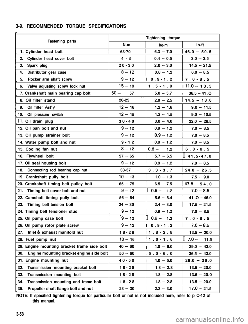
3-9. RECOMMENDED TORQUE SPECIFICATIONS
Fastening partsN-m
Tightening torque
kg-mlb-ft
1. Cylinder head bolt1 63-7016.3 - 7.01 46.0 - 50.5
2.Cylinder head cover bolt4-50.4-0.53.0-3.5
3.Spark plug20-302.0-3.014.5-21.5
4.Distributor gear case8-120.8-1.26.0-8.5
5.Rocker arm shaft screwI9- 12I 0.9-1.21 7.0-8.5
6.Valve adjusting screw lock nut
7. Crankshaft main bearing cap bolt
8. Oil filter stand
I15- 191 1.5-1.9I ll.O- 13.5
1 50- 5715.0 - 5.7136.5 - 41 .O
I20-25 -. 12.0 - 2.51 14.5 - 18.0
9.Oilfilter Ass’y12-161.2-1.69.0-11.5
10.Oilpressure switch12-151.2-1.59.0-10.5
11. Oil drain plugI30-40I3.0 - 4.0122.0 - 28.5
12. Oil pan bolt and nutI9- 12I0.9 - 1.2I7.0 - 8.5
13. Oil pump strainer bolt
14. Water pump bolt and nut
I9- 12I0.9 - 1.2I7.0 - 8.5
I9-12I0.9 - 1.2I7.0 - 8.5
15. Cooling fan nutI8- 121 0.8- 1.21 6.0-8.5
16. Flywheel boltI57 - 65I5.7 - 6.5I 41.5-47.0
17. Oil seal housing boltI9- 12I0.9 - 1.2I7.0 - 8.5
18.Connecting rod bearing cap nut1 33-37( 3.3-3.71 24.0 - 26.5
19. Crankshaft pully boltIlo- 13I1.0 - 1.3I7.5 - 9.0
20. Crankshaft timing belt pulley bolt
21.Timing belt cover bolt and nut
I65 - 75I6.5 - 7.51 47.5- 54.0
I9- 12I 0.9- 1.21 7-O-8.5
22. Camshaft timing pully boltI56 - 6415.6 - 6.4141 .O - 46.0III
23.Timingbelttensionbolt24-302.4-3.0117.5-21.5
24. Timing belt tensioner studI9- 12I0.9 - 1.2I7.0 - 8.5
25. Oil pump case boltI‘9- 12I 0.9- 1.21 7.0-8.5
26. Oil pump rotor plate screwI9- 12I 0.9-1.21 7-O-8.5
27.Inlet & exhaust manifold nutI18-281 1.8-2.8I13.5 - 20.0
28. Fuel pump nutIlo- 161 1.0-1.6I 7.0- 11.5
29. Engine mounting bracket frame side bolt 140 - 60I ~~~4.0 - 6.0129.0 - 43.0
30.Engine mounting bracket engine side bolt I50 - 601 5.0-6.0136.5 - 43.0
31. Engine mounting nutI40-50I4.0 - 5.01 29.0 - 36.0I1I
32.Transmissionmountingbracketbolt18-281.8-2.8113.5-20.0
33.Transmission mounting bolt18-281.8-2.813.5 -20.0
34.Transmission mounting and framebolt18-281.8-2.813.5 -20.0
35.Propeller shaft flange bolt and nut23 - 302.3-3.017.0-21.5
NOTE: If specified tightening torque for particular bolt or nut is not included here, refer to p O-12 of
this manual.
3-58
Page 133 of 962
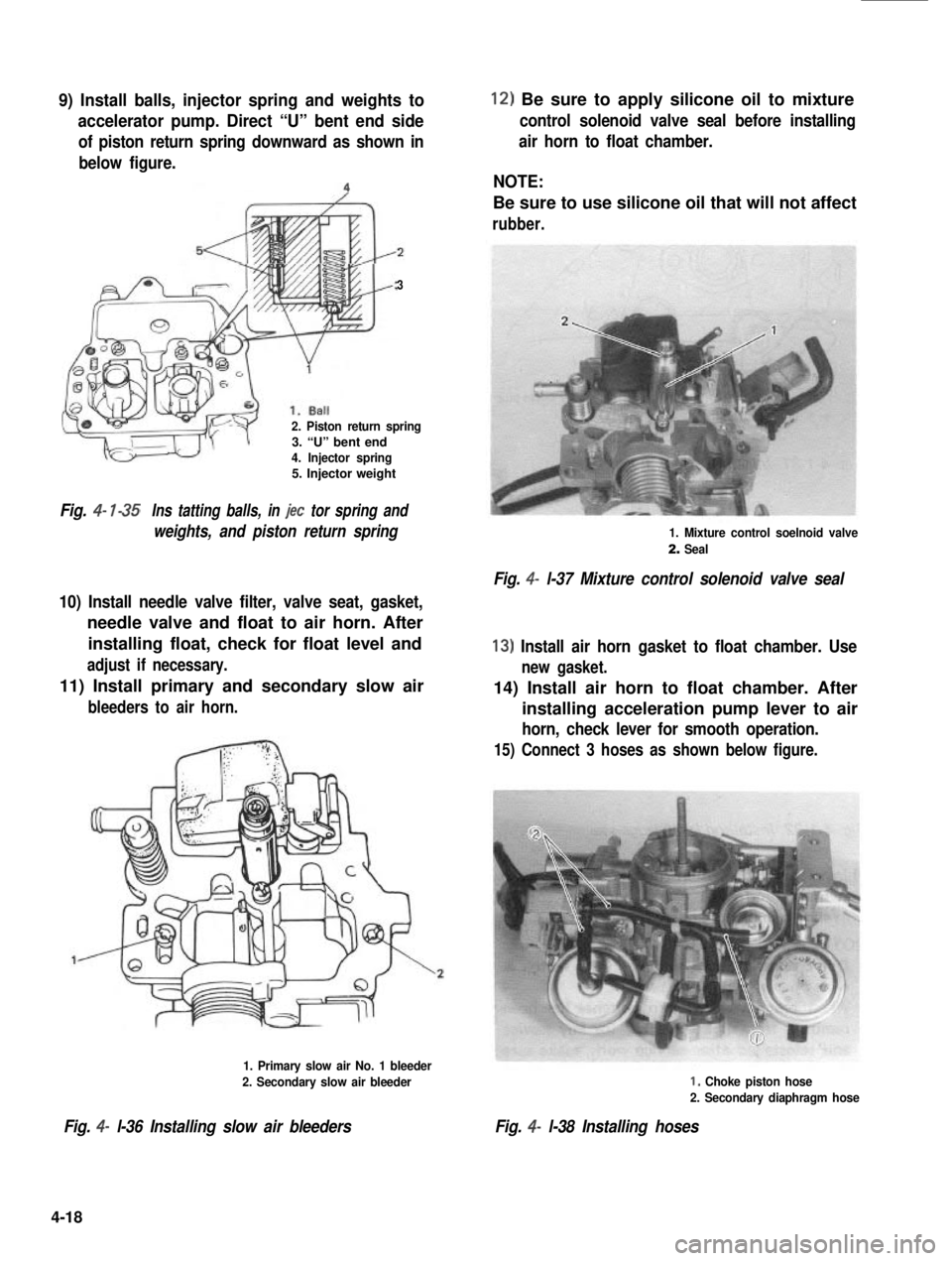
9) Install balls, injector spring and weights to
accelerator pump. Direct “U” bent end side
of piston return spring downward as shown in
below figure.
3
2. Piston return spring3. “U” bent end4. Injector spring5. Injector weight
Fig. 4- l-35Ins tatting balls, in jet tor spring and
weights, and piston return spring
10) Install needle valve filter, valve seat, gasket,
needle valve and float to air horn. After
installing float, check for float level and
adjust if necessary.
11) Install primary and secondary slow air
bleeders to air horn.
1. Primary slow air No. 1 bleeder
2. Secondary slow air bleeder
Fig. 4- l-36 Installing slow air bleeders
12) Be sure to apply silicone oil to mixture
control solenoid valve seal before installing
air horn to float chamber.
NOTE:
Be sure to use silicone oil that will not affect
rubber.
1. Mixture control soelnoid valve
2. Seal
Fig. 4- l-37 Mixture control solenoid valve seal
13) Install air horn gasket to float chamber. Use
new gasket.
14) Install air horn to float chamber. After
installing acceleration pump lever to air
horn, check lever for smooth operation.
15) Connect 3 hoses as shown below figure.
I, Choke piston hose
2. Secondary diaphragm hose
Fig. 4- l-38 Installing hoses
4-18
Page 149 of 962
![SUZUKI GRAND VITARA 1987 Service Repair Manual ,Fuel Pump
[ Rem’oval]
1) Disconnect negative cable from battery.
2) Remove fuel filler cap from fuel filler neck to
release fuel vapor pressure in fuel tank. After
releasing, reinstall the cap.
3) SUZUKI GRAND VITARA 1987 Service Repair Manual ,Fuel Pump
[ Rem’oval]
1) Disconnect negative cable from battery.
2) Remove fuel filler cap from fuel filler neck to
release fuel vapor pressure in fuel tank. After
releasing, reinstall the cap.
3)](/manual-img/20/57437/w960_57437-148.png)
,Fuel Pump
[ Rem’oval]
1) Disconnect negative cable from battery.
2) Remove fuel filler cap from fuel filler neck to
release fuel vapor pressure in fuel tank. After
releasing, reinstall the cap.
3) Disconnect fuel inlet, outlet and return hoses
from fuel pump.
Fuel Filter
[Removal]
1) Disconnect negative cable from battery.
2) Remove fuel filler cap to release fuel vapor
pressure in fuel tank. After releasing, reinstall
the cap.
3) Disconnect inlet and outlet hoses from fuel
filter.
4) Remove fuel filter with clamp.
[Installation]
1) Install filter and clamp, and connect inlet
and outlet hoses to fuel filter.
NOTE:.
The top connection is for outlet hose, the
lower one for inlet hose.
1. Fuel pump
2. Inlet hose3. Outlet hose
4. Return hose
Fig. 4-2-l 1
4) Remove fuel pump from cylinder head.
5) Remove fuel pump rod from cylinder head.
2
1. Fuel pump rod
2. Cylinder head
[Installation]
Reverse removal procedure for installation
using care for the following.
l After oiling it,install fuel pump rod to
cylinder head.
0 Use new fuel pump gasket.
l Make sure for proper hose connection.
0 Upon completion of installation, start engine
and check fuel hose or its joints for leaks.
1.Fuel filter3.From fueltank
2.To fuel pump4.Clamp
Fig.4-2-13
2) Connect negative cable to battery.
3) After installation, start engine and check it
for leaks.
Fuel Tank
[Removal]
1) Disconnect negative cable from battery.
2) Disconnect fuel level gauge lead wire.
3) To release the pressure in fuel tank, remove
fuel filler cap and then, reinstall it.
4) Raise car on hoist.
5) Drain fuel by removing drain plug.
6) Remove filler hose protector.
7) Disconnect filler hose from fuel tank.
.8) Disconnect fuel hosesand pipe from fuel tank.
9) Remove fuel tank.
4-34
Page 467 of 962
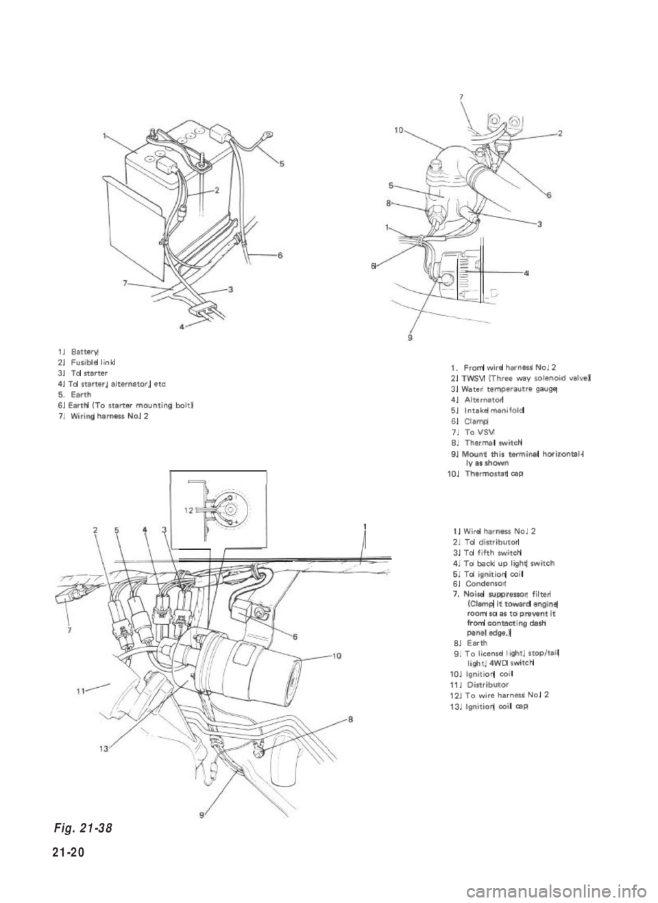
1.Battery2.Fusible link
3.To starter
4. To starter, alternator, etc
5.Earth6. Earth (To starter mounting bolt)7.Wiring harnessNo.2
64
1
I
1.From wire harnessNo.22. TWSV (Three way solenoid valve)
3. Water temperautre gauge4.Alternator5.Intake manifold
6.Clamp
7.ToVSV6.Thermal switch
9. Mount this terminal horizontal-ly as shown
10.Thermostat cap
1. Wire harness No. 2
2. To distributor
3. To fifth switch4. To back up light switch5. To ignition coil6. Condensor
7. Noise suppressor filter(Clamp it toward engineroom so as to prevent itfrom contacting dashpanel edge.)6. Earth9. To license light, stop/taillight, 4WD switch
10. Ignition coil
11. Distributor12. To wire harness No. 2
13. Ignition coil cap
Fig. 21-38
21-20