1987 SUZUKI GRAND VITARA lights
[x] Cancel search: lightsPage 244 of 962
![SUZUKI GRAND VITARA 1987 Service Repair Manual [Carrier and hold-down]
The battery carrier and hold-down clamp should
be clean and free from corrosion before instal-
ling the battery. The carrier should be in good
condition so that it will support SUZUKI GRAND VITARA 1987 Service Repair Manual [Carrier and hold-down]
The battery carrier and hold-down clamp should
be clean and free from corrosion before instal-
ling the battery. The carrier should be in good
condition so that it will support](/manual-img/20/57437/w960_57437-243.png)
[Carrier and hold-down]
The battery carrier and hold-down clamp should
be clean and free from corrosion before instal-
ling the battery. The carrier should be in good
condition so that it will support the battery
securely and keep it level.
Make certain there are no parts in carrier before
installing the battery.
To prevent the battery from shaking in its
carrier, the hold-down bolts should be tight but
not over tightened.
[Visual inspection]
Check for obvious damage, such as cracked or
broken case or cover, that could permit loss of
electrolyte. If obvious damage is noted, replace
the battery. Determine cause of damage and
correct as needed.
Check the battery terminal and cords for corro-
sion. If any, it should be cleaned.
[Built-in indicator]
This sealed battery has a built-in temperature
compensated indicator in the top of the battery.
This indicator is to be used with the following
diagnostic procedure. When observing the
indicator, make sure that the battery has a clean
top. A light may be needed in some poorly-lit
areas.
Under normal operation, two indications can
be seen
2
Clear
RedCHARGING
NECESSARY
Fig. lo-23
l Clear with Red Dot
This means the discharging battery. In this case,
charge the battery until the indicator will be
blue with red dot. The charging and electrical
systems should also be checked at this time. If
any defective is found, correct it. While charging
it, if the battery feels hot 52°C (125” F), or if
violent gassing or spewing of electrolyte through
the vent hole occurs, discontinue charging or
reduce charging rate.
[Jump starting in case of emergency with
auxiliary (booster) battery]
NOTE:
l Do not push or tow the vehicle to start.
Damage to the emission system and/or to
other parts of the vehicle may result.
8 Both booster and discharged battery should
be treated carefully when using jumper cables.
Follow the procedure outlined below, being
careful not to cause sparks:
CAUTION:
l Departure from these conditions or the
procedure below could result in: (1)
Serious personal injury (particularly to
eyes) or property damage from such
causes as battery explosion, battery acid,
or electrical burns; and/or (2) damage to
electronic components of either vehicle.
l Never expose battery to open flame or
electric spark-batteries generate a gas
which is flammable and explosive.
l Remove rings,watches,and other
jewelry. Wear approved eye protection.
l Do not allow battery fluid to contact
eyes, skin, fabrics, or painted surfaces -
fluid is a corrosive acid. Flush any con-
tacted area with water immediately and
thoroughly. Be careful that metal tools
or jumper cables do not contact the
positive battery terminal (or metal in
contact with it) and any other metal on
the car, because a short circuit could
occur. Batteries should always be kept
out of the reach of children.
1) Set parking brake and place transmission in
neutral. Turn off the ignition, turn off lights
and all other electrical loads.
2) Check electrolyte level. If level is below low
level line, replace battery.
NOTE:
When jump starting an engine with charging
equipment, be sure equipment used is 12volt
and negative ground. Do not use 24volt charging
equipment. Using each equipment can cause
serious damage to the electrical system or
electronic parts.
10-11
Page 427 of 962

19-8. MAINTENANCE SERVICE
ROAD TESTING BRAKES
Brakes should be tested on dry, clean, smooth
and reasonably level roadway which is not
crowned. Road test brakes by making brake
applications with both light and heavy pedal
forces at various speeds to determine if the car
stops evenly and effectively.
Also drive car to see if it leads to one side or the
other without brake application. If it does,
check tire pressure, front end alignment and
front suspension attachments for looseness.
See diagnosis chart for other causes.
BRAKE FLUID LEAKS
Check master cylinder fluid levels. While a slight
drop in reservoir level does result from normal
lining wear, an abnormally low level indicates a
leak in the system.In such a case, check the
entire brake system for leakage. If even a slight
evidence of leakage is noted, the cause should be
corrected or defective parts should be replaced.
BRAKE FLUID LEVEL INSPECTION
Be sure to use particular brake fluid either as
marked on reservoir cap of that car or recom-
mended in owner’s manual which comes along
with that car.
Use of any other fluid is strictly prohibited.
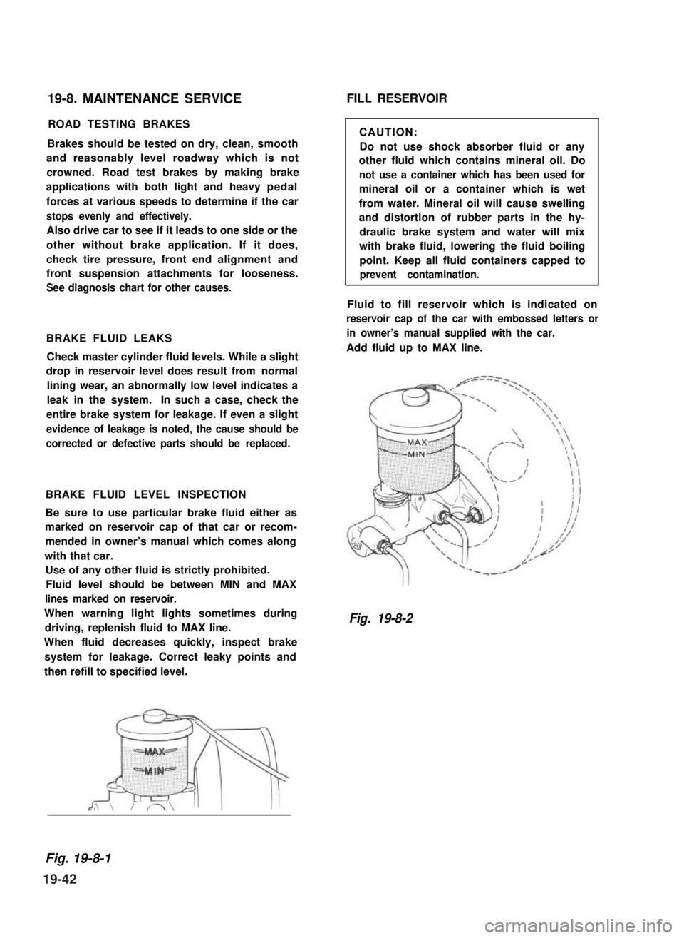
Fluid level should be between MIN and MAX
lines marked on reservoir.
When warning light lights sometimes during
driving, replenish fluid to MAX line.
When fluid decreases quickly, inspect brake
system for leakage. Correct leaky points and
then refill to specified level.
FILL RESERVOIR
CAUTION:
Do not use shock absorber fluid or any
other fluid which contains mineral oil. Do
not use a container which has been used for
mineral oil or a container which is wet
from water. Mineral oil will cause swelling
and distortion of rubber parts in the hy-
draulic brake system and water will mix
with brake fluid, lowering the fluid boiling
point. Keep all fluid containers capped to
prevent contamination.
Fluid to fill reservoir which is indicated on
reservoir cap of the car with embossed letters or
in owner’s manual supplied with the car.
Add fluid up to MAX line.
Fig. 19-8-2
Fig. 19-8-1
19-42
Page 451 of 962

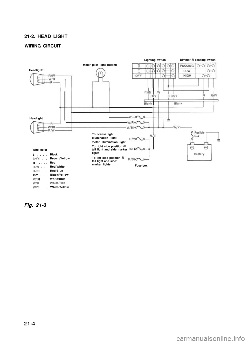
21-2. HEAD LIGHT
WIRING CIRCUIT
Headlight
HeadlightI
Meter pilot light (Beam)II
I
4
Lighting switchDimmer & passing switch
To license light,illumination light,
meter illumination light
Wire color
B. . . .Black
Br/Y . .Brown/Yellow
R.....Red
R/w . . .Red/White
RIBI . .Red/Blue
B/Y . . .Black/Yellow
WIBI . .White/Blue
W/R .WhitelRed
W/Y .White/Yellow
To right side position &tail light and side markerRIGlights
iIB
To left side position 81tail light and side’RIBId
marker lightsFuse box
Fig. 21-3
21-4
Page 452 of 962

HEADLIGHT INSPECTION
1.Lighting (Low beam, High beam, Passing)
2. Mounting
3.Dirt and cracks on lenses
4.Main beam axis direction and brightness
HEADLIGHT BEAM SETTING (STANDARD PROCEDURE)
Before setting the headlight beams, adjust air pressures of four tires to a specified value respectively. Move
the vehicle up and down by hand to settle its attitude. Then move it over a flat surface. There are available
a variety of headlight beams setting methods (e.g., the screen method using a focusing tester, etc.). How-
ever, the method described here does not use such tester.
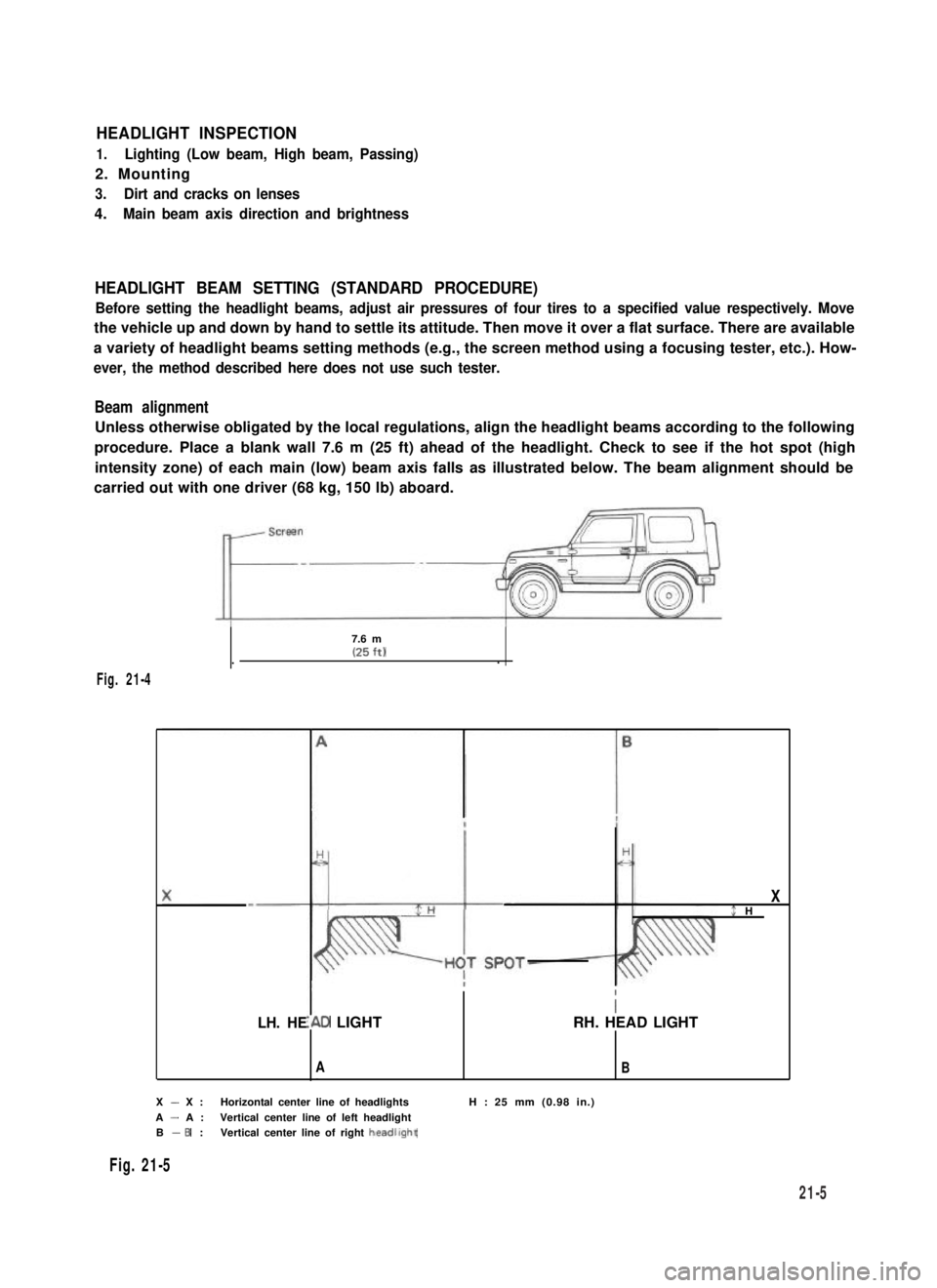
Beam alignment
Unless otherwise obligated by the local regulations, align the headlight beams according to the following
procedure. Place a blank wall 7.6 m (25 ft) ahead of the headlight. Check to see if the hot spot (high
intensity zone) of each main (low) beam axis falls as illustrated below. The beam alignment should be
carried out with one driver (68 kg, 150 lb) aboard.
7.6 m(25 ft)..
Fig. 21-4
LH. HE
X$ H
I
I\D LIGHTRH. HEAD LIGHT
AB
X - X :Horizontal center line of headlightsH : 25 mm (0.98 in.)
A - A :Vertical center line of left headlightB - 6 :Vertical center line of right headllght
Fig. 21-5
21-5
Page 455 of 962

INSPECTION
1) Trouble diagnosis
Symptom
1. Lights will not come on in either left or
right group of light.
2. Hazard light comes on but turn signal
lights will not.
3. No light comes on; or lights light up but
do not flicker.
4. Turn signal lights are satisfactory, but
hazard light will not come on.
5. Flickering freueqncy is erratic, or lights
remain lit.
6. Turning on hazard warning switch lights up
only one group of lights.
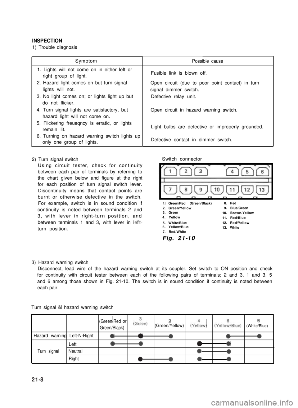
2) Turn signal switch
Using circuit tester, check for continuity
between each pair of terminals by referring to
the chart given below and figure at the right
for each position of turn signal switch lever.
Discontinuity means that contact points are
burnt or otherwise defective in the switch.
For example, switch is in sound condition if
continuity is noted between terminals 2 and
3, with lever in right-turn position, and
between terminals 1 and 3, with lever in left-
turn position.
Possible cause
Fusible link is blown off.
Open circuit (due to poor point contact) in turn
signal dimmer switch.
Defective relay unit.
Open circuit in hazard warning switch.
Light bulbs are defective or improperly grounded.
Defective contact in dimmer switch.
Switch connector
I”””yrm-
1.Green/Red (Green/Black)8.Red
2.Green/Yellow9.Blue/Green3.Green10.Brown/Yellow4.Yellow11.Red/Blue
5.White/Blue12.Red/Yellow6.Yellow/Blue13.White7.Red/White
Fig. 21-10
3) Hazard warning switch
Disconnect, lead wire of the hazard warning switch at its coupler. Set switch to ON position and check
for continuity with circuit tester between each of the following pairs of terminals; 2 and 3, 1 and 3, 5
and 6 among those shown in Fig. 21-10. The switch is in sound condition if continuity is noted between
each pair.
Turn signal & hazard warning switch
1(Green/Redor
Green/Black)
(Grien)2(Green/Yellow) (Yeiow)5(YelloiIBlue) (White/Blue)
Hazard warning Left-N-Right0a-000
Left00l0
Turn signalNeutral*0
Rightla*0
21-8