Page 1130 of 1865
7C TROUBLESHOOTING
Evaluation
Condition Possible cause
Worn oil pump
In all ranges Insufficient line
pressure
Oil leakage from oil pump, control
valve, and/or transaxle case
Stuck pressure regulator valve
In D, 2, and 1 Rear clutch slipping
Above specification In D range only One-way clutch slipping
In 2 range only Brake band slipping
Low and reverse brake slipping
Brake band slipping
In R range only Road test to determine if cause is low and reverse brake or reverse clutch:
a) Engine braking in 1 range Front clutch b) No engine braking in 1 range .... Low and reverse brake
Within specification All shift control elements within transaxle functioning normally
Below specification Engine out of tune Below specification
One-way clutch slipping within torque converter
76G07C-026
7C—16
Page 1134 of 1865
7C TROUBLESHOOTING
STEP 5 (OIL PRESSURE TEST)
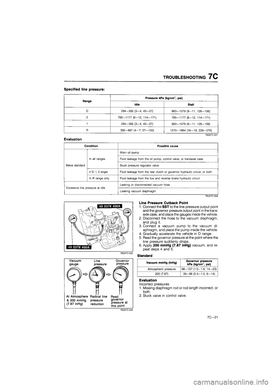
This step determines line pressure, and governor pressure to check the hydraulic components and
for oil leakage.
Line Pressure Test
Preparation
1. Connect the SST to the line pressure output point.
2. Connect a tachometer to the engine.
3. Follow the test preparation procedure show in STEP 2 (STALL TEST).
Procedure
76G07C-030
1. Start the engine and verify that the idle speed is 950-5° rpm.
2. Shift the selector lever to D range.
3. Read the line pressure at idle.
4. Depress the brake pedal firmly with the left foot, and gradually depress the accelerator pedal with
the right foot.
5. Read the line pressure as soon as the engine speed becomes constant; then release the accelera-
tor pedal.
Caution
Steps 4 to 5 must be done within 5 seconds.
5. Shift the selector lever to N range and let the engine idle for one minute or more.
6. Read the line pressure at idle and engine stall speeds for each range in the same manner.
7C—20
Page 1135 of 1865

TROUBLESHOOTING 7C
Specified line pressure:
Range Pressure kPa (kg/cm2, psi) Range
Idle Stall
D 294-392 (3-4, 43-57) 883-1079 (9—11, 128-156)
2 785—1177 (8—12, 114—171) 785-1177 (8—12, 114-171)
1 294-392 (3-4, 43—57) 883-1079 (9—11, 128—156)
R 392-687 (4-7, 57-100) 1570—1864 (16—19, 228-270)
76G07C-031
Evaluation
Condition Possible cause
Below standard
In all ranges
Worn oil pump
Below standard
In all ranges Fluid leakage from the oil pump, control valve, or transaxle case
Below standard
In all ranges
Stuck pressure regulator valve Below standard
In D, 1, 2 ranges Fluid leakage from the rear clutch or governor hydraulic circuit, or both
Below standard
In R range only Fluid leakage from the low and reverse brake hydraulic circuit
Excessive line pressure at idle Leaking or disconnected vacuum hose Excessive line pressure at idle
Leaking vacuum diaphragm
76G07C-032
76G07C-033
Vacuum
gauge Line
pressure
Governor pressure
At Atmosphere Radical line Read
& 200 mmHg pressure governor
(7.87 inHg) reduction
Line Pressure Cutback Point
1. Connect the SST to the line pressure output point
and the governor pressure output point in the trans-
axle case, and place the gauges inside the vehicle.
2. Disconnect the hose to the vacuum diaphragm,
and plug it.
3. Connect a vacuum pump to the vacuum di-
aphragm, and place the pump inside the vehicle.
4. Gradually accelerate the vehicle in D range.
5. Read the governor pressure at the point where the
line pressure suddenly drops.
6. Apply 200 mmHg (7.87 inHg) vacuum, and re-
peat steps 4 and 5.
Standard
Vacuum mmHg (InHg) Governor pressure kPa (kg/cm2, psi)
Atmospheric pressure 98-157 (1.0—1.6, 14-23)
200 (7.87) 39-98 (0.4-1.0, 6—14)
Evaluation
Incorrect pressures
1. Missing diaphragm rod or rod length incorrect, or
both.
2. Stuck valve in control valve.
76G07C-034
7C—21
Page 1189 of 1865

INSPECTION AND REPAIR 7C
CONTROL VALVE BODY
Precaution
(1) Pay close attention when handling the control valve because it consists of the most precise and
delicate parts of the transaxle.
(2) Neatly arrange the removed parts in order to avoid mixing up similar parts.
(3) Disassemble the control valve assembly and thoroughly clean it when the clutch and/or brake
bands are burned, and/or when the automatic transaxle fluid is degenerated.
Disassembly
Disassemble in the sequence shown in the figure.
2.5—3.4 N m _ (25—35 cm-kg, (7) 22—30 in-lb)
2.5—3.4 N-m (25—35 cm-kg 22—30 in-lb)
. 2.5—3.4 N-m (25—35 cm-kg, 22—30 In-lb)
2.5—3.4 N-m (25—35 cm-kg, 22—30 in-lb)
5—7 N-m {50—70 cm-kg, 43—61 In-lb)
2.5—3.4 N-m (25—35 cm-kg, 22—30 in-lb)
2.5—3.4 N-m (25—35 cm-kg, 22—30 in-lb)
5—7 N-m (50—70 cm-kg, 43—61 in-lb)
^ - 3—4 N-m (30—40 cm-kg, 26—35 in-lb)
76G07C-201
1. Manual valve
2. Oil strainer
3. Lower body
4. Separator plate
5. Throttle relief ball and
spring
6. Orifice check valve and
spring
7. Sub-body
8. Orifice check valve
9. Side plate
10. Vacuum throttle valve
11. Spring
12. Throttle backup valve
13. Downshift valve
14. Spring
15. Side plate
16. Modifier valve
17. 2-3 shift valve
18. Spring
19. 2-3 shift plug
20.1-2 shift valve
21. Spring
22. Side plate
23. Spring
24. Second lock valve
25. Pressure regulator sleeve
26. Pressure regulator plug
27. Spring seat
28. Spring
29. Pressure regulator valve
30. Upper body
7C-75
Page 1190 of 1865
7C INSPECTION AND REPAIR
Inspection
Check the following and replace any faulty parts.
1. Damaged or worn valves
2. Damaged oil passage
3. Cracked or damaged valve body
4. Operation of each valve
5. Weakened spring 76go7c-2o2
Spring
Name Outer dia. mm (in) Free length mm (in) Wire dia. mm (in)
Throttle backup 7.3 (0.287) 36.0 (1.417) 0.8 (0.031)
Downshift 5.55 (0.219) 21.9 (0.862) 0.55 (0.022)
2-3 shift 6.9 (0.272) 41.0 (1.614) 0.7 (0.028)
1-2 shift 6.4 (0.252) 31.63 (1.245) 0.4 (0.016)
Second lock 5.55 (0.219) 33.5 (1.319) 0.55 (0.022)
Pressure regulator 11.7 (0.461) 43.0 (1.693) 1.2 (0.047)
Throttle relief 7.0 (0.276) 11.2 (0.441) 0.9 (0.035)
Orifice check 5.0 (0.197) 15.5 (0.610) 0.23 (0.009)
76G07C-203
Valve Location
63U07B-500
7C-76
Page 1239 of 1865

HYDRAULIC CIRCUIT 7C
HYDRAULIC CIRCUIT
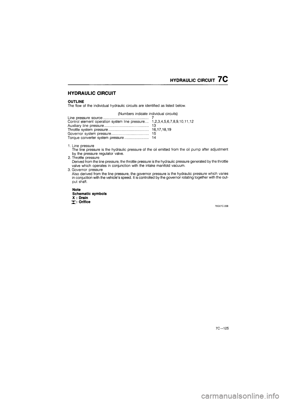
OUTLINE
The flow of the individual hydraulic circuits are identified as listed below.
(Numbers indicate individual circuits)
Line pressure source 7
Control element operation system line pressure.... 1,2,3,4,5,6,7,8,9,10,11,12
Auxiliary line pressure 13
Throttle system pressure 16,17,18,19
Governor system pressure 15
Torque converter system pressure 14
1. Line pressure
The line pressure is the hydraulic pressure of the oil emitted from the oil pump after adjustment
by the pressure regulator valve.
2. Throttle pressure
Derived from the line pressure, the throttle pressure is the hydraulic pressure generated by the throttle
valve which operates in conjunction with the intake manifold vacuum.
3. Governor pressure
Also derived from the line pressure, the governor pressure is the hydraulic pressure which varies
in conjuction with the vehicle's speed. It is controlled by the governor rotating together with the out-
put shaft.
Note
Schematic symbols
X : Drain
Orifice
76G07C-338
7C-125
Page 1241 of 1865
HYDRAULIC CIRCUIT 7C
R RANGE
Band servo
Release side
Oil cooler
Low and reverse brake 1 pressure Vacuum diaphragm Kick-down solenoid Rear clutch pressure
Front clutch pressure
Downshift valve H Oil pump Vacuum throttle valve
Throttle backup valve
Orifice check valve
Modifier 15| valve
2-3 shift valve
Second lock valve
Orifice valve Pressure regulator valve
Line pressure t4s2
Operating line pressure
Governor pressure
Torque converter
Throttle pressure Secondary x governor valve Primary governor valve
76G07C-340
7C—127
Page 1242 of 1865
7C HYDRAULIC CIRCUIT
N RANGE
Oil cooler
Low and reverse brake •l pressure Vacuum diaphragm Kick-down solenoid
Rear clutch pressure
Front clutch pressure
Downshift valve 11 Oil pump Throttle backup valve
Vacuum throttle valve
x 18 Orifice YjI check valve H [ Throttle relief I valve
Modifier 15| valve Orifice check
I
valve
Orifice check valve 11 j! Pressure regulator valve
Line pressure
Governor pressure
Torque converter
Throttle pressure Primary governor valve Secondary x governor valve
76G07C-341
7C—128