Page 784 of 1865

QUICK START SYSTEM (QSS) 5
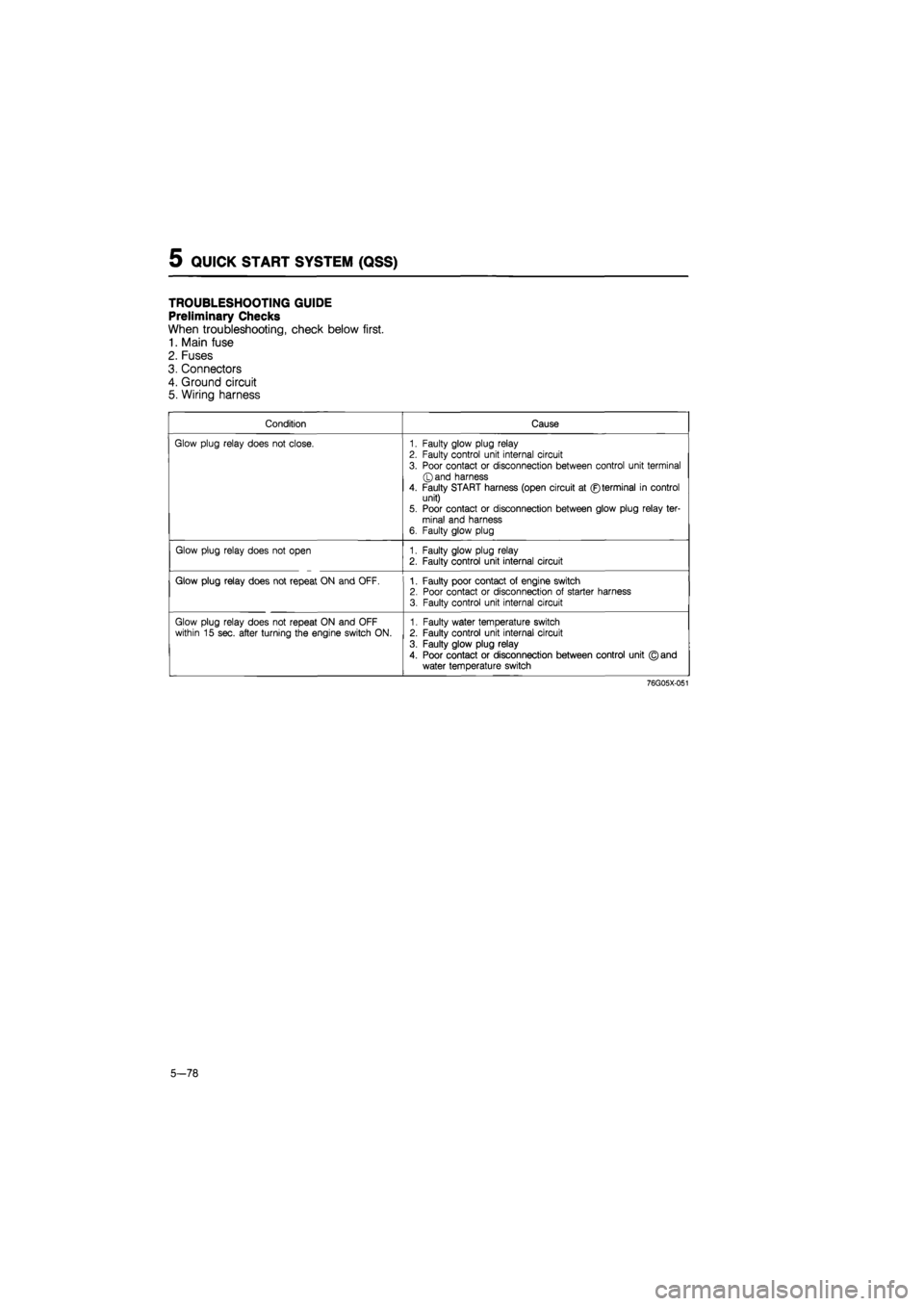
TROUBLESHOOTING GUIDE
Preliminary Checks
When troubleshooting, check below first.
1. Main fuse
2. Fuses
3. Connectors
4. Ground circuit
5. Wiring harness
Condition Cause
Glow plug relay does not close. 1. Faulty glow plug relay 2. Faulty control unit internal circuit
3. Poor contact or disconnection between control unit terminal ©and harness
4. Faulty START harness (open circuit at ©terminal in control unit) 5. Poor contact or disconnection between glow plug relay ter-minal and harness 6. Faulty glow plug
Glow plug relay does not open 1. Faulty glow plug relay 2. Faulty control unit internal circuit
Glow plug relay does not repeat ON and OFF. 1. Faulty poor contact of engine switch 2. Poor contact or disconnection of starter harness 3. Faulty control unit internal circuit
Glow plug relay does not repeat ON and OFF within 15 sec. after turning the engine switch ON. 1. Faulty water temperature switch 2. Faulty control unit internal circuit
3. Faulty glow plug relay
4. Poor contact or disconnection between control unit © and water temperature switch
76G05X-051
5-78
Page 785 of 1865

QUICK START SYSTEM (QSS) 5
CONTROL UNIT
Inspection
1. Connect a voltmeter to the control unit as shown
in the figure.
2. Check the voltage of the terminal.
3. Replace the control unit if necessary.
Caution
If the proper voltage is not indicated on the
voltmeter, check all wiring connections and
finally, check that component.
63G05X-337
Control Unit Connector
Terminal Input Output Connection to Operation condition Voltage Remark
for 6 sec. approx. 12V
L (GW) O Glow plug relay Engine switch: ON (No cranking) after 6 sec.
OV 12V Coolant temperature; below 30°C (86°F) after 6 sec.
OV Coolant temperature; above 30°C (86°F)
H
(B) — — Ground OV
E (BW) 0 Engine switch (ON) Engine switch: ON approx. 12V
F
(BR) O Engine switch (START) Engine switch: START approx. 12V
C o
Water
temperature switch
Engine switch: ON (No cranking)
approx. 12V Coolant temperature; below 30°C (86°F)
(BrB) o
Water
temperature switch
Engine switch: ON (No cranking)
approx. OV Coolant temperature;
above 30°C (86°F)
At cranking OV <- 12V
B 0 Glow plug
For 15 sec. after engine has started OV <-> 12V Coolant temperature;
(Gr) 0 Glow plug After 15 sec. OV below 30°C (86 °F)
After engine has started OV Coolant temperature; above 30°C (86°F)
K o Indicator Engine switch: ON
For 3 sec. OV
(WR) o Indicator Engine switch: ON after 3 sec. approx. 12V
76G05X-052
u® x y i © © X 1
© © X ®
5-79
Page 786 of 1865

5 QUICK START SYSTEM (QSS)
Glow plug relay GLOW PLUG RELAY
Inspection
1. As shown in the figure, connect the battery and
an ohmmeter to the relay.
2.
If
the ohmmeter shows continuity when the battery
is connected, and no continuity when the battery
is disconnected, the relay is good.
3. Replace the relay if it fails this test.
4BG05X-123
GLOW PLUG
Inspection
1. Check the continuity between the positive termi-
nal of the glow plug and cylinder head with a cir-
cuit tester.
2. If there is no continuity, replace the glow plug.
4BG05X-121
Removal
Remove in the following order:
1. Glow plug connector attaching nut.
2. Glow plug connector.
3. Glow plug
Installation
Install the glow plug, reverse order of removal.
76G05X-053
63G05X-336
5-80
WATER TEMPERATURE SWITCH
Removal
Remove the water temperature switch from the
radiator.
Installation
Install in the reverse order of removal.
Inspection
1. Place the water temperature switch in water with
a thermometer and heat the water gradually.
2. Check the temperature at which continuity exists
between the terminals.
3. Replace the switch, if necessary.
Specified temperature: above 28—32°C
(82—90°F)
Page 793 of 1865
CLUTCH MASTER CYLINDER 6
CLUTCH MASTER CYLINDER
LHD RHD
13—22 N-m (1.3—2.2 m-kg, 9-16 ft-lb)
•19—26 N-m (1.9—2.6 m-kg, 14—19 ft-lb)
^13—22 N-m (1.3—2.2 m-kg, 9—16 ft-lb)
1. Clutch pipe
2. Nuts
76G06X-011
3. Clutch master cylinder
4. Gasket
76G06X-012
REMOVAL
1. Remove the ABS relay box. (LHD)
2. Disconnect the clutch pipe with the SST.
3. Remove the mounting nuts.
4. Remove the clutch master cylinder.
Caution
Clutch fluid will damage painted surfaces. Be
sure to use a container or rags to collect it.
If fluid does get on a painted surface, wipe it
off immediately with a rag.
86U06X-010
6-7
Page 797 of 1865
CLUTCH RELEASE CYLINDER
INSTALLATION
1. Install the clutch master cylinder.
2. Tighten the mounting nuts.
Tightening torque:
19—26 Nm (1.9—2.6 m-kg, 14—19 ft-lb)
3. Tighten the clutch pipe flare nut securely with the
SST.
Tightening torque:
13—22 N m (1.3—2.2 m-kg, 9—16 ft-lb)
76G06X-021 4. Install the ABS relay box. (LHD)
After installation
1. Perform air bleeding. (Refer to page 6—14.)
2. Verify that there is no leakage.
3. Perform a road test.
CLUTCH RELEASE CYLINDER
86U06X-019
6-11
Page 1289 of 1865

10
STEERING SYSTEM
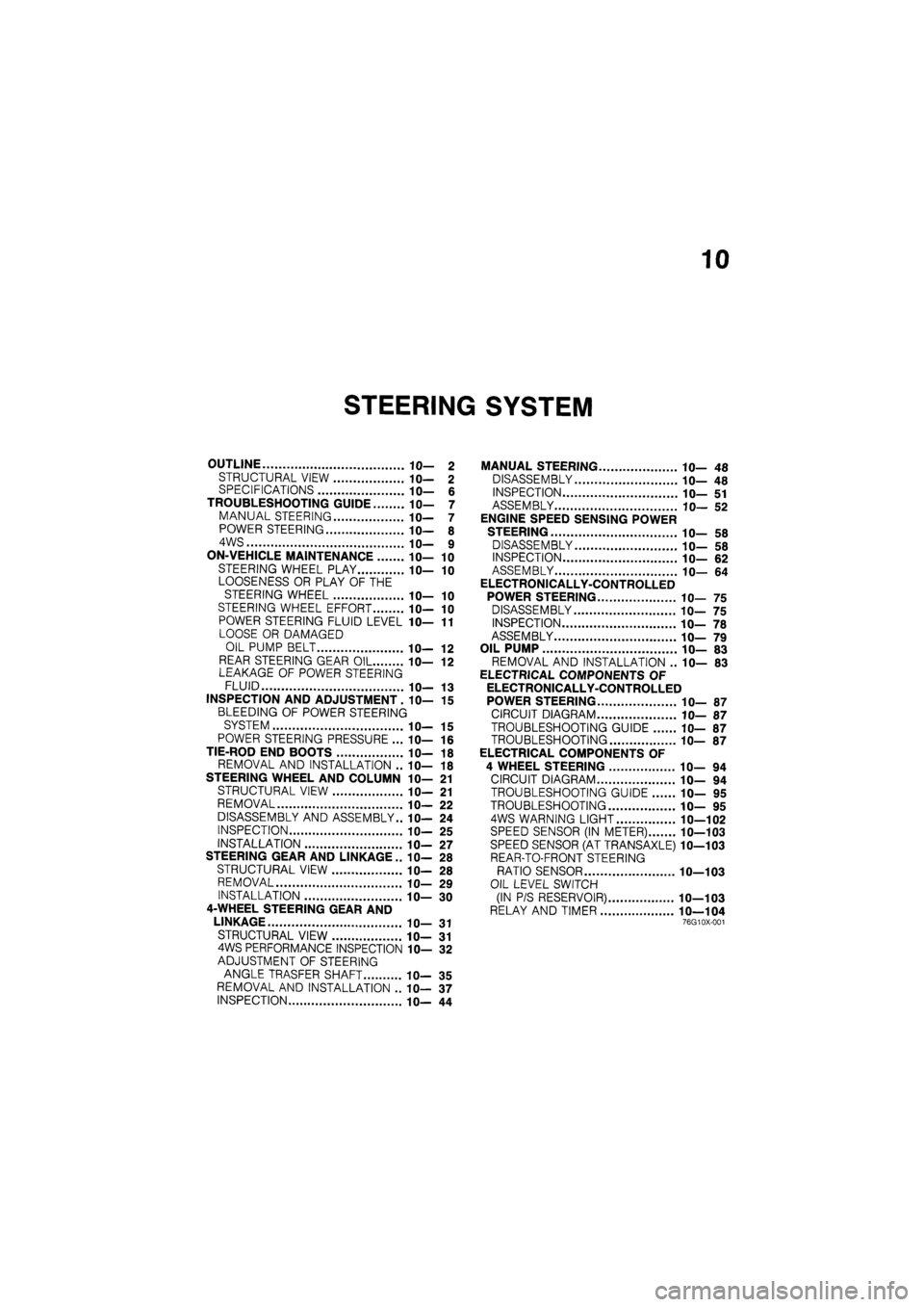
OUTLINE 10— 2
STRUCTURAL VIEW 10— 2 SPECIFICATIONS 10— 6
TROUBLESHOOTING GUIDE 10— 7
MANUAL STEERING 10— 7
POWER STEERING 10— 8
4WS 10— 9
ON-VEHICLE MAINTENANCE 10— 10
STEERING WHEEL PLAY 10— 10
LOOSENESS OR PLAY OF THE
STEERING WHEEL 10— 10
STEERING WHEEL EFFORT 10— 10
POWER STEERING FLUID LEVEL 1 fl-11
LOOSE OR DAMAGED
OIL PUMP BELT IC— 12
REAR STEERING GEAR OIL 10— 12 LEAKAGE OF POWER STEERING
FLUID 10— 13
INSPECTION AND ADJUSTMENT. 10— 15
BLEEDING OF POWER STEERING
SYSTEM 10— 15
POWER STEERING PRESSURE ... 10— 16
TIE-ROD END BOOTS 10— 18
REMOVAL AND INSTALLATION .. 10— 18
STEERING WHEEL AND COLUMN 10— 21
STRUCTURAL VIEW 10— 21
REMOVAL 10— 22
DISASSEMBLY AND ASSEMBLY.. 10— 24
INSPECTION 10— 25
INSTALLATION 1 fl-27
STEERING GEAR AND LINKAGE .. IC— 28
STRUCTURAL VIEW 10— 28
REMOVAL 10— 29
INSTALLATION 10— 30
4-WHEEL STEERING GEAR AND
LINKAGE 10— 31
STRUCTURAL VIEW 10— 31 4WS PERFORMANCE INSPECTION 10— 32
ADJUSTMENT OF STEERING
ANGLE TRASFER SHAFT 10— 35
REMOVAL AND INSTALLATION .. 10— 37
INSPECTION 10— 44
MANUAL STEERING 10— 48
DISASSEMBLY 10— 48
INSPECTION 10— 51
ASSEMBLY 10— 52
ENGINE SPEED SENSING POWER
STEERING 10— 58
DISASSEMBLY 10— 58
INSPECTION 10— 62
ASSEMBLY 10— 64
ELECTRONICALLY-CONTROLLED
POWER STEERING 10— 75
DISASSEMBLY 10— 75
INSPECTION 10— 78
ASSEMBLY 10— 79
OIL PUMP 10— 83
REMOVAL AND INSTALLATION .. 10— 83
ELECTRICAL COMPONENTS OF
ELECTRONICALLY-CONTROLLED
POWER STEERING 10— 87
CIRCUIT DIAGRAM 10— 87
TROUBLESHOOTING GUIDE 10— 87
TROUBLESHOOTING 10— 87
ELECTRICAL COMPONENTS OF
4 WHEEL STEERING 10— 94
CIRCUIT DIAGRAM 10— 94
TROUBLESHOOTING GUIDE 10— 95
TROUBLESHOOTING 10— 95
4WS WARNING LIGHT 10—102
SPEED SENSOR (IN METER) 10—103
SPEED SENSOR (AT TRANSAXLE) 10—103
REAR-TO-FRONT STEERING
RATIO SENSOR 10—103
OIL LEVEL SWITCH
(IN P/S RESERVOIR) 10—103
RELAY AND TIMER 10—104 76G10X-001
Page 1293 of 1865
OUTLINE 10
86U10X-005
1. Reserve tank
2. Oil pump
3. Front steering gear assembly
4. Speed sensor
5. Control unit
6. Steering angle transfer shaft
7. Solenoid valves
8. Rear steering gear assembly
9. Steering wheel
10. Steering shaft
11. Relay and timer
Note
4-wheel steering is abbreviated 4WS.
10—5
Page 1319 of 1865
4-WHEEL STEERING GEAR AND LINKAGE 1 0
4-WHEEL STEERING GEAR AND LINKAGE
STRUCTURAL VIEW
1. Reserve tank
2. Oil pump
3. Front steering gear assembly
4. Speed sensor
5. Control unit
6. Steering angle transfer shaft
7. Solenoid valve
8. Rear steering gear assembly
9. Steering wheel
10. Steering shaft
11. Relay and timer
86U10X-056
10—31