Page 1390 of 1865
1 0 ELECTRICAL COMPONENTS OF 4-WHEEL STEERING
flashes
Replace control unit
4WS-9 Failure of control unit, alternator, or wiring harness
Start engine,
I
Check voltage between terminal of control unit con-nector and body ground.
Terminal Voltage
G(B) OV
H (B) OV
K(G) Approx. 12V
L (G) Approx. 12V
N(B) OV
OK
NG
Check 4WS relay and timer (Refer to page 10—103) -
OK
Check battery, harness, and alternator.
NG
Turn ignition switch OFF. Start engine. Check if 4WS warning light flashes or illuminates.
NO
Momentary problem (If warning light often flashes or illuminates, check battery and alter-nator. Replace control unit if necessary).
YES
Replace control unit.
Replace relay and timer
76G10X-031
4WS WARNING LIGHT
1. Turn the ignition switch OFF.
2. Turn the ignition switch ON, and check that the
4WS warning light illuminates.
3. If there is no illumination, check the warning light
bulb and wiring harness.
Replace the control unit if necessary.
86U10X-232
10-102
Page 1392 of 1865
1 0 ELECTRICAL COMPONENTS OF 4-WHEEL STEERING
86U10X-237
76G10X-047
10—104
RELAY AND TIMER
1. Start the engine.
2. Check voltage between each terminal of the relay
and timer connector and a body ground.
Terminal Voltage
a 12V
b 12V
d 12V
i 12V
1 OV
If the voltage is not as specified, replace the fuse
or repair the harness.
3. Check voltage between each terminal and a body
ground with the engine running.
Terminal Voltage
f 12V
h 12V
4. Check that the voltage of f and h terminal is 12V
for approximately 7 to 10 seconds after the igni-
tion switch is turned OFF.
If not, replace the relay and timer.
Page 1393 of 1865

11
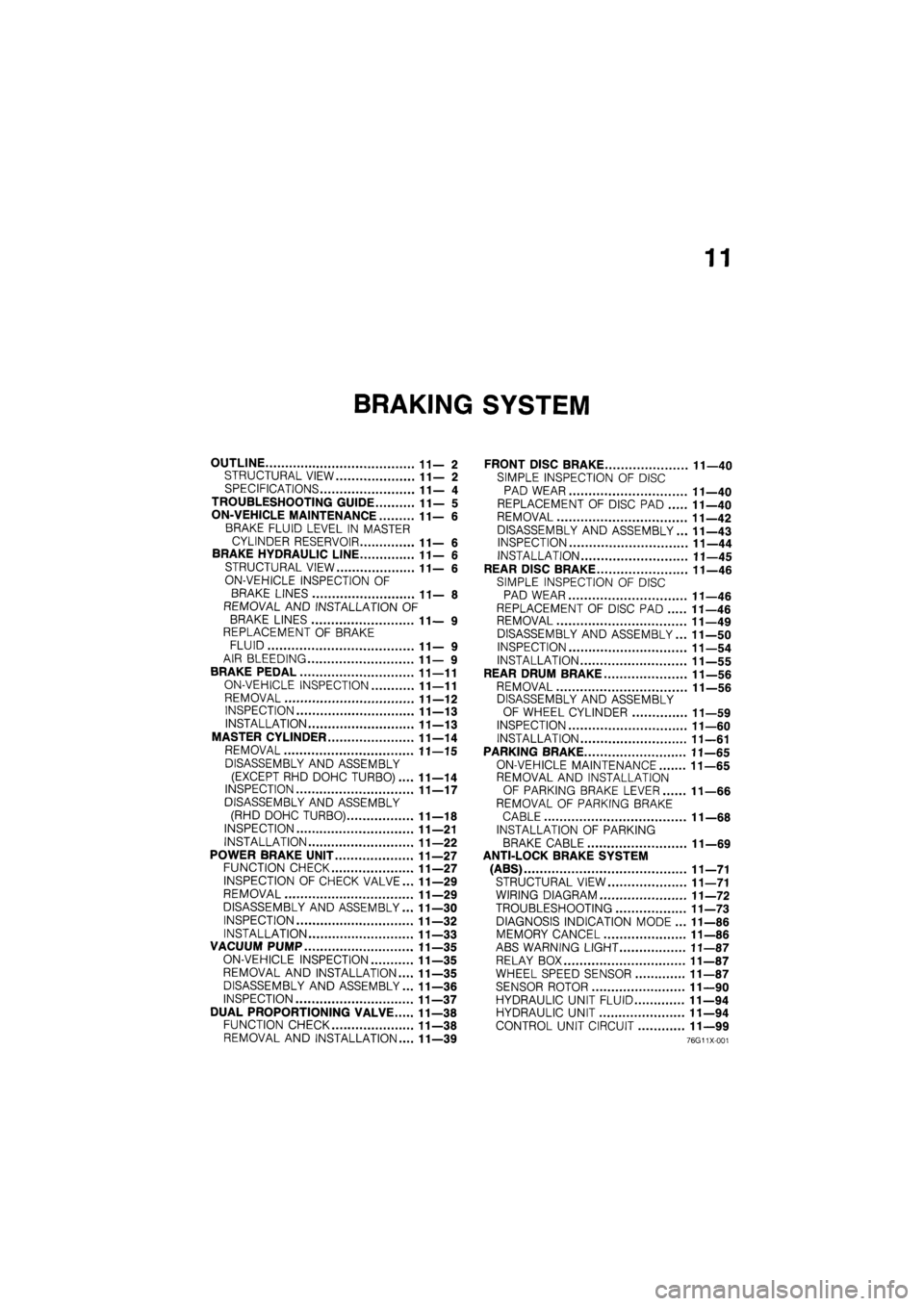
BRAKING SYSTEM
OUTLINE 11—2
STRUCTURAL VIEW 11—2
SPECIFICATIONS 11— 4
TROUBLESHOOTING GUIDE 11— 5
ON-VEHICLE MAINTENANCE 11—6
BRAKE FLUID LEVEL IN MASTER
CYLINDER RESERVOIR 11— 6
BRAKE HYDRAULIC LINE 11—6
STRUCTURAL VIEW 11—6
ON-VEHICLE INSPECTION OF
BRAKE LINES 11— 8
REMOVAL AND INSTALLATION OF
BRAKE LINES 11— 9
REPLACEMENT OF BRAKE
FLUID 11— 9
AIR BLEEDING 11— 9
BRAKE PEDAL 11—11
ON-VEHICLE INSPECTION 11—11
REMOVAL 11—12
INSPECTION 11—13
INSTALLATION 11—13
MASTER CYLINDER 11—14
REMOVAL 11—15
DISASSEMBLY AND ASSEMBLY
(EXCEPT RHD DOHC TURBO).... 11—14
INSPECTION 11—17
DISASSEMBLY AND ASSEMBLY
(RHD DOHC TURBO) 11—18
INSPECTION 11—21
INSTALLATION 11—22
POWER BRAKE UNIT 11—27
FUNCTION CHECK 11—27
INSPECTION OF CHECK VALVE... 11—29
REMOVAL 11—29
DISASSEMBLY AND ASSEMBLY... 11—30
INSPECTION 11—32
INSTALLATION 11—33
VACUUM PUMP 11—35
ON-VEHICLE INSPECTION 11—35
REMOVAL AND INSTALLATION.... 11—35
DISASSEMBLY AND ASSEMBLY... 11—36
INSPECTION 11—37
DUAL PROPORTIONING VALVE 11—38
FUNCTION CHECK 11—38
REMOVAL AND INSTALLATION.... 11—39
FRONT DISC BRAKE 11—40
SIMPLE INSPECTION OF DISC
PAD WEAR 11—40
REPLACEMENT OF DISC PAD 11—40
REMOVAL 11—42
DISASSEMBLY AND ASSEMBLY... 11—43
INSPECTION 11—44
INSTALLATION 11—45
REAR DISC BRAKE 11—46
SIMPLE INSPECTION OF DISC
PAD WEAR 11—46
REPLACEMENT OF DISC PAD 11—46
REMOVAL 11—49
DISASSEMBLY AND ASSEMBLY... 11—50
INSPECTION 11—54
INSTALLATION 11—55
REAR DRUM BRAKE 11—56
REMOVAL 11—56
DISASSEMBLY AND ASSEMBLY
OF WHEEL CYLINDER 11—59
INSPECTION 11—60
INSTALLATION 11—61
PARKING BRAKE 11—65
ON-VEHICLE MAINTENANCE 11—65
REMOVAL AND INSTALLATION
OF PARKING BRAKE LEVER 11—66
REMOVAL OF PARKING BRAKE
CABLE 11—68
INSTALLATION OF PARKING
BRAKE CABLE 11—69
ANTI-LOCK BRAKE SYSTEM
(ABS) 11—71
STRUCTURAL VIEW 11—71
WIRING DIAGRAM 11—72
TROUBLESHOOTING 11—73
DIAGNOSIS INDICATION MODE ... 11—86
MEMORY CANCEL 11—86
ABS WARNING LIGHT 11—87
RELAY BOX 11—87
WHEEL SPEED SENSOR 11—87
SENSOR ROTOR 11—90
HYDRAULIC UNIT FLUID 11—94
HYDRAULIC UNIT 11—94
CONTROL UNIT CIRCUIT 11—99
76G11X-001
Page 1395 of 1865
OUTLINE 11
86U11X-003
1. Front disc brake
2. Hydraulic unit
3. Pipe joint
4. Master cylinder
5. Power brake unit
6. Relay box
7. Control unit
8. Wheel speed sensor
9. Sensor rotor
10. Rear disc brake
11. Parking brake lever
12. Parking brake cable
Front disc brake
(Ventilated disc)
Rear disc brake
(Solid disc)
Rear drum brake
(Leading-trailing)
Page 1463 of 1865
ANTI-LOCK BRAKE SYSTEM (ABS) 1 1
ANTI-LOCK BRAKE SYSTEM (ABS)
STRUCTURAL VIEW
1. Hydraulic unit 4. Sensor rotor (front) 7. Wheel speed sensor (rear)
2. Relay box 5. Wheel speed sensor (front) 8. Sensor rotor (rear)
3. Control unit 6. Check connector
11—71
Page 1465 of 1865

ANTI-LOCK BRAKE SYSTEM (ABS) 1 1
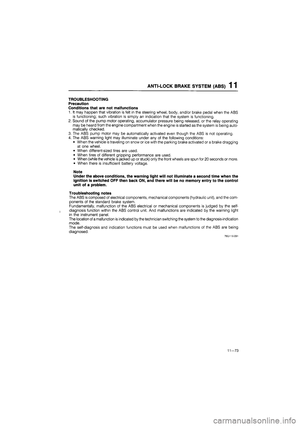
TROUBLESHOOTING
Precaution
Conditions that are not malfunctions
1. It may happen that vibration is felt in the steering wheel, body, and/or brake pedal when the ABS
is functioning; such vibration is simply an indication that the system is functioning.
2. Sound of the pump motor operating, accumulator pressure being released, or the relay operating
may be heard from the engine compartment when the engine is started as the system is being auto-
matically checked.
3. The ABS pump motor may be automatically activated even though the ABS is not operating.
4. The ABS warning light may illuminate under any of the following conditions:
• When the vehicle is traveling on snow or ice with the parking brake activated or a brake dragging
at one wheel.
• When different-sized tires are used.
• When tires of different gripping performance are used.
• When (while the vehicle is jacked up or stuck) only the front wheels are spun for 20 seconds or more.
• When there is insufficient battery voltage.
Note
Under the above conditions, the warning light will not illuminate a second time when the
ignition is switched OFF then back ON, and there will be no memory entry to the control
unit of a problem.
Troubleshooting notes
The ABS is composed of electrical components, mechanical components (hydraulic unit), and the com-
ponents of the standard brake system.
Fundamentally, malfunction of the ABS electrical or mechanical components is judged by the self-
diagnosis function within the ABS control unit. And malfunctions are indicated by the warning light
in the instrument panel.
The location
of
a malfunction is indicated by the technician switching the system to the diagnosis-indication
mode.
The self-diagnosis and indication functions must be used when malfunctions of the ABS are being
diagnosed.
76G11X-091
11—73
Page 1466 of 1865

1 1 ANTI-LOCK BRAKE SYSTEM (ABS)
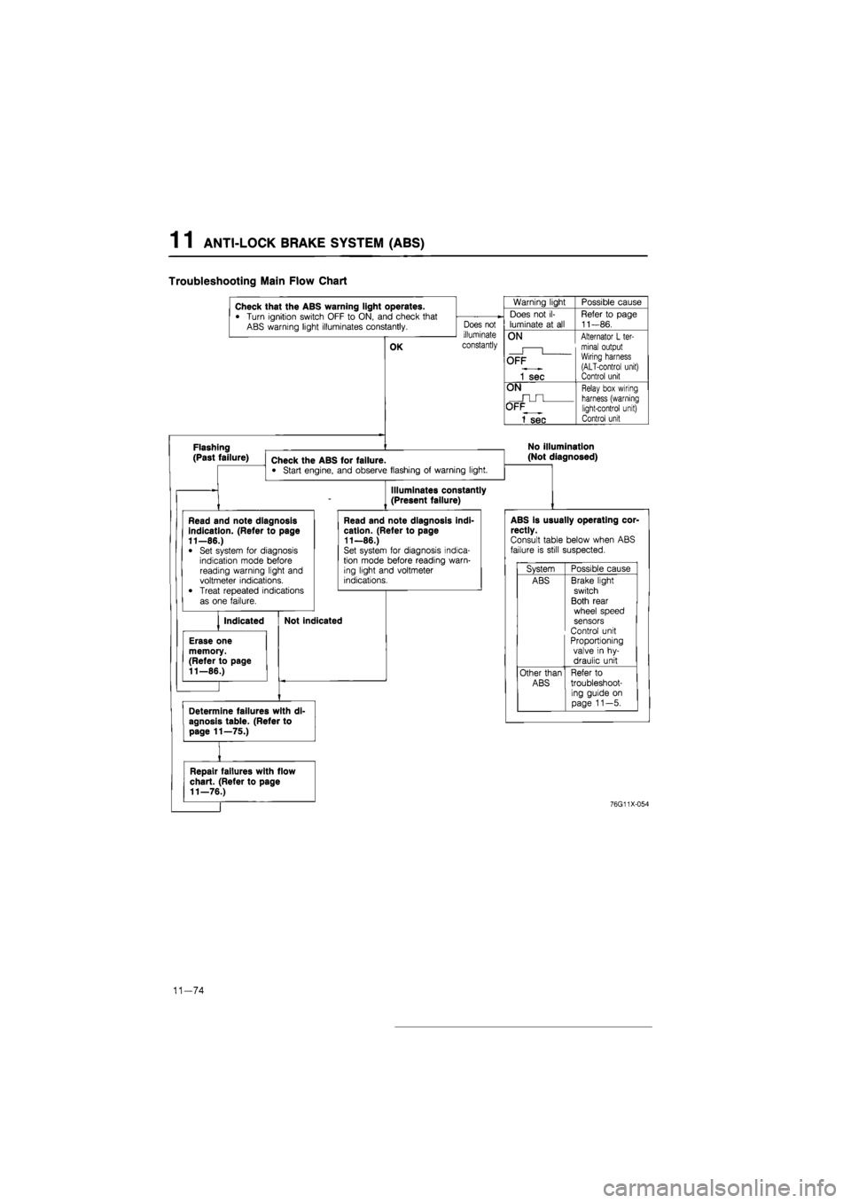
Troubleshooting Main Flow Chart
Check that the ABS warning light operates.
• Turn ignition switch OFF
to
ON, and check that ABS warning light illuminates constantly.
Flashing (Past failure)
OK
Check the ABS for failure.
• Start engine, and observe flashing
of
warning light.
Does not
illuminate
constantly
Warning light Possible cause
Does
not il-
luminate
at all
Refer
to
page 11—86.
ON
Alternator
L
ter-minal output Wiring harness (ALT-control unit) Control unit
OFF
1 sec
Alternator
L
ter-minal output Wiring harness (ALT-control unit) Control unit
ON
Relay box wiring harness (warning light-control unit) Control unit
OFF
1 sec
Relay box wiring harness (warning light-control unit) Control unit
No illumination
(Not diagnosed)
Illuminates constantly
(Present failure)
ABS is usually operating cor-rectly.
Consult table below when ABS failure
is
still suspected.
System Possible cause
ABS Brake light switch
Both rear wheel speed sensors
Control unit Proportioning
valve
in hy-
draulic unit
Other than Refer
to
ABS troubleshoot-ing guide
on
page 11—5.
Repair failures with flow
chart. (Refer to page
11—76.)
76G11X-054
11-74
Page 1467 of 1865

ANTI-LOCK BRAKE SYSTEM (ABS) 1 1
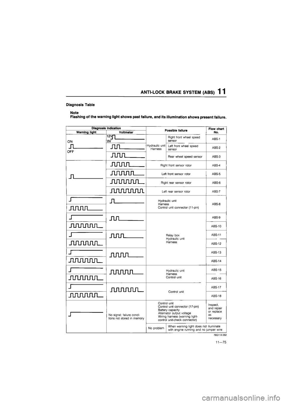
Diagnosis Table
Note
Flashing of the warning light shows past failure, and its illumination shows present failure.
Diagnosis indication Possible failure Flow chart
No. Warning light Voltmeter Possible failure Flow chart
No.
ON
n
i2vn
OV
Hydraulic unit Harness
Right front wheel speed
sensor ABS-1
ON
n nn
Hydraulic unit Harness Left front wheel speed sensor ABS-2
OFF
Hydraulic unit Harness Left front wheel speed sensor ABS-2
OFF
nnn
Hydraulic unit Harness
Rear wheel speed sensor ABS-3
n
nnnn
Right front sensor rotor ABS-4
n
nnnnn
Left front sensor rotor ABS-5
JLilTUITLTL
Right rear sensor rotor ABS-6
jirLruiJum
Left rear sensor rotor ABS-7
J n
Hydraulic unit Harness
Control unit connector (11-pin)
ABS-8
nnnn
Hydraulic unit Harness
Control unit connector (11-pin)
ABS-8
J nn
Relay box
Hydraulic unit
Harness
ABS-9
jumruiTL
Relay box
Hydraulic unit
Harness
ABS-10
j nnn
Relay box
Hydraulic unit
Harness
ABS-11
jinnjuuL
Relay box
Hydraulic unit
Harness ABS-12
j nnnn
Relay box
Hydraulic unit
Harness
ABS-13
jiruuirirL
Relay box
Hydraulic unit
Harness
ABS-14
j nnnnn
Hydraulic unit Harness Control unit
ABS-15
juuuiruL
Hydraulic unit Harness Control unit ABS-16
j JinjiruifL.
Control unit
ABS-17
jiruinjiri—
JinjiruifL.
Control unit
ABS-18
j
No signal; failure condi-tions not stored
in
memory
Control unit Control unit connector (17-pin) Battery capacity Alternator output voltage Wiring harness (warning light-control unit-check connector)
Inspect, and repair or replace as necessary
j
No signal; failure condi-tions not stored
in
memory
No problem When warning light does
not
illuminate with engine running and
no
jumper wire
76G11X092
11-75