Page 1788 of 1865

OUTLINE 16
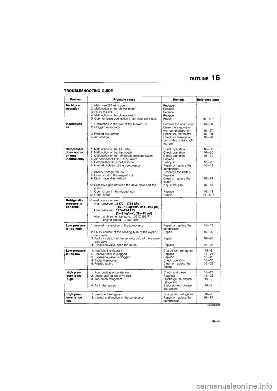
TROUBLESHOOTING GUIDE
Problem Probable cause Remedy Reference page
No blower
1. Main fuse (30
A) is
open Replace
operation
2 Malfunction
of
the blower motor Replace 3. Faulty resistor Replace 4. Malfunction
of
the blower switch Replace 5. Open
or
loose connection
in an
electrical circuit Repair 16—6,
7
Insufficient
1. Obstruction
in
the inlet
of
the blower unit Remove the obstruction 16-26
air
2. Clogged evaporator Clean the evaporator
with compressed
air
16-27 3. Frosted evaporator Check the thermostat 16-30 4. Air leakage Check for leakage
at
16-26 both sides
of
the cool-
ing unit
Compressor
1. Malfunction
of
the A/C relay Check operation 16—30
does not run,
2. Malfunction
of
the thermostat Check operation 16—30
or runs
3. Malfunction
of
the refrigerant-pressure switch Check operation 16—31
insufficiently
4.
Air
conditioner fuse (15
A)
failure Replace 5. Compressor drive belt
is
loose Readjust 16—23
6. Internal problem
of
the compressor Repair
or
replace
the
16—13
compressor 7. Battery voltage too low Recharge the battery 8. Layer short
in
the magnet coil Replace 9. Clutch face dirty with
oil
Clean
or
replace the 16-13
clutch 10. Excessive gap between the drive plate and
the
Adjust the gap 16-13
pulley
11. Open circuit
in
the magnet coil Replace 16—13
12 Open circuit Repair 16-6,
7
Refrigeration
Normal pressures are:
pressure is
High pressure
1472—1765 kPa
abnormal (15—18 kg/cm2, 214—255 psi)
Low pressure
197—294 kPa
(2—3 kg/cm2, 29—42 psi)
when: ambient temperature 35°C (95°F)
engine speed 1,500
rpm
Low pressure
1. Internal malfunction
of
the compressor Repair
or
replace the 16-13
is too high
compressor
2. Faulty contact
of
the sensing bulb
of
the expan-Repair 16-26
sion valve 3. Faulty insulation
of
the sensing bulb
of
the expan-Repair 16—26
sion valve
4. Expansion valve open too much Replace 16—26
Low pressure
1. Insufficient refrigerant Charge with refrigerant 16-8
is too low
2. Receiver-drier
is
clogged Replace 16-25
3. Expansion valve
is
clogged Replace 16-26
4. Faulty thermostat Check operation 16-30 5. Frosted piping Clean
or
replace the 16—29
piping
High pres-
1. Poor cooling
of
condenser Check and clean 16-24
sure is too
2. Loose cooling fan drive belt Readjust 16—23
high
3. Too much refrigerant Discharge the excess 16-8
refrigerant 4.
Air in
the system Evacuate and charge 16-8
the system
High pres-
1. Insufficient refrigerant Charge with refrigerant 16-8
sure is too
2. Internal malfunction
of
the compressor Repair
or
replace the 16-13
low
compressor
76G16X-004
16—5
Page 1813 of 1865

1 6 A/C RELAY
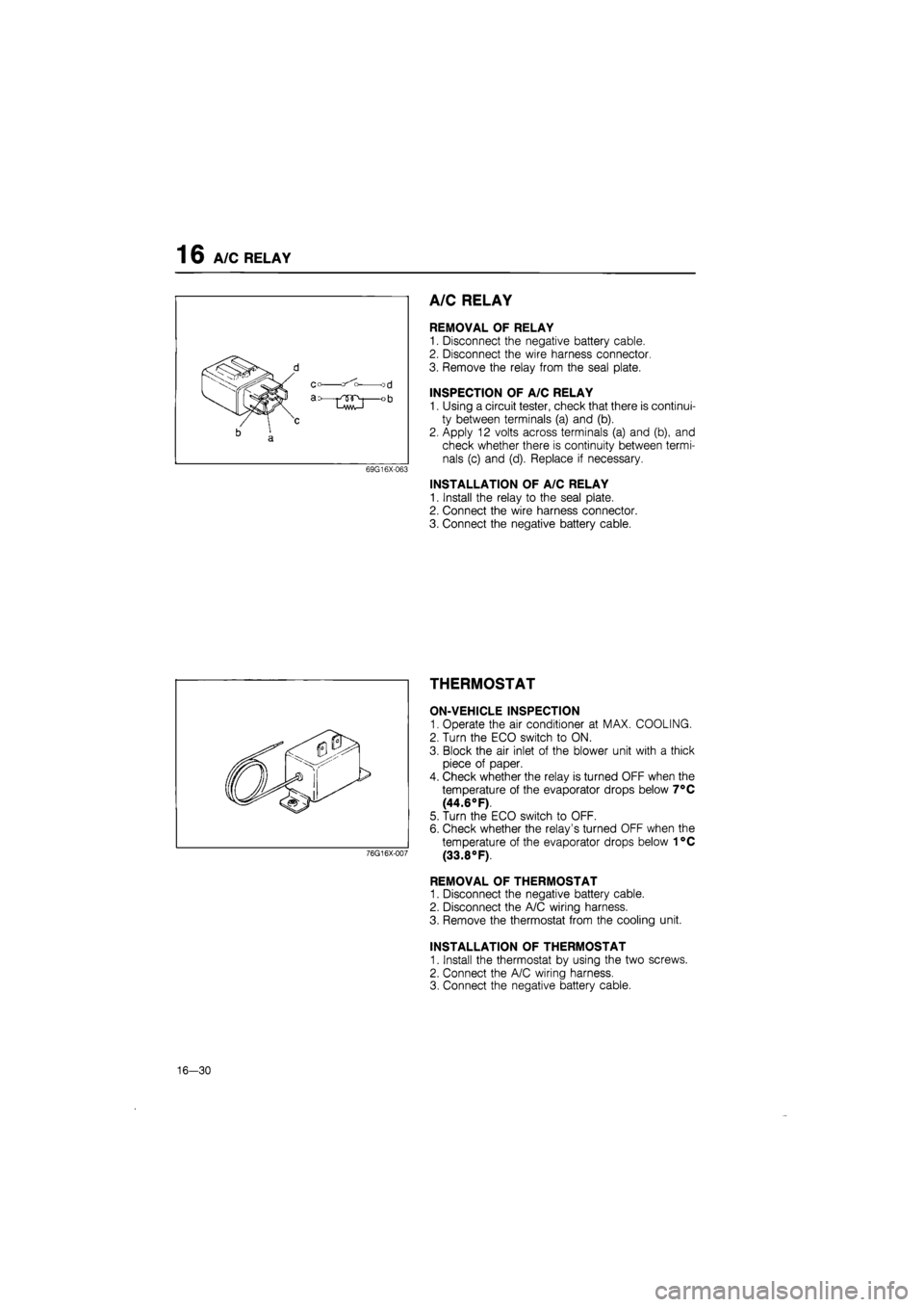
A/C RELAY
REMOVAL OF RELAY
1. Disconnect the negative battery cable.
2. Disconnect the wire harness connector
3. Remove the relay from the seal plate.
INSPECTION OF A/C RELAY
1. Using a circuit tester, check that there is continui-
ty between terminals (a) and (b).
2. Apply 12 volts across terminals (a) and (b), and
check whether there is continuity between termi-
nals (c) and (d). Replace if necessary.
INSTALLATION OF A/C RELAY
1. Install the relay to the seal plate.
2. Connect the wire harness connector.
3. Connect the negative battery cable.
THERMOSTAT
ON-VEHICLE INSPECTION
1. Operate the air conditioner at MAX. COOLING.
2. Turn the ECO switch to ON.
3. Block the air inlet of the blower unit with a thick
piece of paper.
4. Check whether the relay is turned OFF when the
temperature of the evaporator drops below 7°C
(44.6°F).
5. Turn the ECO switch to OFF.
6. Check whether the relay's turned OFF when the
temperature of the evaporator drops below 1°C
(33.8°F).
REMOVAL OF THERMOSTAT
1. Disconnect the negative battery cable.
2. Disconnect the A/C wiring harness.
3. Remove the thermostat from the cooling unit.
INSTALLATION OF THERMOSTAT
1. Install the thermostat by using the two screws.
2. Connect the A/C wiring harness.
3. Connect the negative battery cable.
76G16X-007
16-30
Page 1834 of 1865

30 TECHNICAL DATA
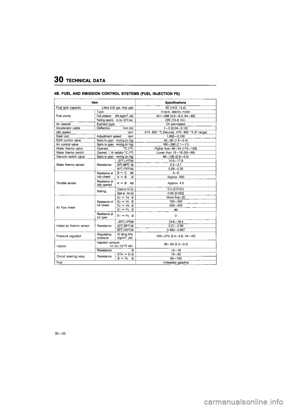
4B. FUEL AND EMISSION CONTROL SYSTEMS (FUEL INJECTION FE)
Item Specifications
Fuel tank capacity Liters (US gal, Imp gal) 60 (15.9, 13.2)
Fuel pump
Type In-tank, electric motor
Fuel pump Fuel pressure kPa (kg/cm2, psi) 441-588 (4.5-6.0, 64-85) Fuel pump
Feeding capacity cc (cu in)/10 sec. 220 (13.4) min.
Air cleaner Element type Oil permeated
Accelerator cable Deflection
mm
(in) 1—3 (0.04-0.12)
Idle speed
rpm
ATX: 800 +58 (Neutral), ATX: 900 +600
(P
range)
Dash
pot
Adjustment speed
rpm
1,900-2.100
EGR control valve Starts
to
open mmHg (in Hg) 40-60 (1.6-2.4)
Air control valve Starts
to
open mmHg (in Hg) 180-280 (7.1-11)
Water thermo valve Opened
°C
(°F) Higher than 46—54 (115-129)
Water thermo switch Opened
At
radiator
°C
(°F) Lower than 15—19 (59—66)
Vacuum switch valve Starts to open mmHg (in Hg) 66—106 (2.6—4.2)
Water thermo sensor Resistance
-20°C (-4°F)k!) 14.5-17.8
Water thermo sensor Resistance 20°C (68°F)
kQ
2.2-2.7 Water thermo sensor Resistance
80°C (176°F)k!i 0.28-0.35
Throttle sensor
Resistance
at
fully closed
B
C kQ
4-6
Throttle sensor
Resistance
at
fully closed A
« B Q
Approx.
500
Throttle sensor Resistance
at
fully opened A
«• B kQ
Approx.
4.5
Throttle sensor
Setting Closed at mm (in) 0.4 (0.0157)
Throttle sensor
Setting Open at mm (in) 0.55 (0.022)
Air flow meter
Resistance
of
full closed
E2 « Vs fi
More than
20
Air flow meter
Resistance
of
full closed
E2 •+ Vc 0
100-300
Air flow meter
Resistance
of
full closed
E2 VB Q
200-400 Air flow meter
Resistance
of
full closed
Ei
•+ Fc Q OO
Air flow meter
Resistance
at
full open Ei
•+ Fc Q
0
Intake
air
thermo sensor Resistance
-20°C M°RkQ 13.6-18.4
Intake
air
thermo sensor Resistance 20°C (68°F) kfi 2.21—2.69 Intake
air
thermo sensor Resistance
60°C (140°RkQ 0.493-0.667
Pressure regulator Regulating pressure At idling kPa
(kg/cm
,
psi) 235-275 (2.4—2.8, 34-40)
Injector
Injection amount cc (cu in)/15 sec. 38-53 (2.3-3.2) Injector
Resistance
Q
12-16
Circuit opening relay Resistance STA Ei Q 15-30 Circuit opening relay Resistance B
Fc fi
80-150
Fuel Unleaded gasoline
30-20