Page 1745 of 1865
1 5 SLIDING SUNROOF
CIRCUIT DIAGRAM
BATTEHY
© © P o-
B
[Fj -
80A
X-01
ff
WR [F] X-01 MAIN
X-06
FUSE
X-ffij
4 |
-WR [D]-
JB-09
©
Hit
LR
R|
LR [Fr) REAR HATCH
^T-06 T-06
BlFrj
Bl
i iii
-LR [In] -
15®
— JB-IO ® ROOM
^JB-03(
[
B[D| i
-J1
Unleaded Fuel (Except Sweden & West Germany)
X-D2
IGN SW
VX-OZ
BW |D|
r-oe T-01 JB-10 © 5SA@ ^JB-07®
= = = = = ^ T-05
BrW"|Frj RW IFi]
^ X-jfi
RW [R]
BrW'[H2| RW [R2|
LR
T-04
SUNROOF REUY No.1
I fp LW-' ly
4f - = - --
LW
S.G LY
REAR HATCH MOTOR
T-01 Connector Between Interior Light Harness [In] and Sunroof
T-02 Sunroof Sw
LG
LW G (±±±
B
l. LY
GO
LW LG ±±±
LY
L B
T-03 Sunroof Motor
Y
L LY YG
pL=LX Jh
TTTT1
YR
B
LG LW
YG
LY L Y
Ntttt) TTTT
LW LG
B YR
T-04 Sunroof Relay No
1
G
Y G
r±±±-
B
« L
T-05 Sunroof Relay No
2
G
YR G
B
x YG
T-06 Rear Hatch Sw
|
BrW
B
LR
RW
5 Door
T-07 Rear Hatch Motor [R3] RW
*
B;W
*
15-90
86U15X-149
Page 1746 of 1865

SLIDING SUNROOF 1 5
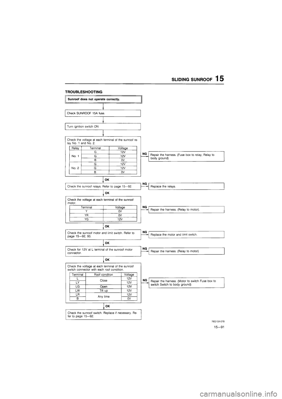
TROUBLESHOOTING
Sunroof does not operate correctly.
Check SUNROOF 15A fuse.
Turn ignition switch
ON
Check the voltage
at
each terminal
of
the sunroof
re-
lay No.
1
and No.
2.
Relay Terminal Voltage
No.
1
G 12V
No.
1
G 12V No.
1
B OV
No.
2
G 12V
No.
2
G 12V No.
2
B OV
OK
Check the sunroof relays. Refer
to
page 15—92.
OK
Check the voltage
at
each terminal
of
the sunroof motor.
OK
Check the sunroof motor and limit switch. Refer
to
page 15—92,
93.
OK
Check
for
12V
at L
terminal
of
the sunroof motor connector.
OK
Check the voltage
at
each terminal
of
the sunroof switch connector with each roof condition.
OK
Terminal Voltage
Y OV
YR OV
YG 12V
Terminal Roof condition Voltaae
L Close 12V
LY Close 12V
LG Open 12V
LW Tilt
up
12V
LR Any time 12V
B Any time OV
Check the sunroof switch. Replace
if
necessary.
Re-
fer
to
page 15—92.
NG
Repair the harness. (Fuse box
to
relay, Relay
to
body ground)
NG
Replace the relays.
NG
Repair the harness. (Relay
to
motor).
NG
Replace the motor and limit switch.
NG
Repair the harness. (Relay
to
motor)
NG
Repair the harness. (Motor
to
switch Fuse box
to
switch Switch
to
body ground)
76G15X-078
15—91
Page 1747 of 1865
1 5 SLIDING SUNROOF
INSPECTION
Switch
Use an ohmmeter to check the continuity of the ter-
minals of the switch.
If continuity is not as indicated, replace the switch.
Terminal
Position
OFF
Slide
SW
Tilt
SW
OPEN
CLOSE
UP
DOWN
2a
O-
2b 6a
-O
6b
O-
6c
O
6d
O
76U15X-156
O—O:
Indicates conductive
6e 6f
-O
-O
-o
o—o
6e 6c 6a /-i 1 '-v.
=!= ck
T T T
6f 6d 6b
e c a
nWi
ri
a c
b e f
76U15X-314
Relay
1. Check the continuity between a—b and c—f.
2. Apply power source to the terminal a.
3. Connect the negative lead to the terminal b.
4. Check the continuity between c—e.
Motor
1. Disconnect the connector of the motor.
2. Apply power source to YR and connect Y to the
ground.
3. Check that motor turns in the direction from the tilt
up, to the closed, to the open position.
4. Reverse the connection and check motor turns
from the open, to the closed, to the tilt up position.
76U15X-315
15-92
Page 1761 of 1865
1 5 POWER DOOR LOCK
TROUBLESHOOTING
Terminal Voltage
WG 12V
B OV
Check the voltage
at GB
terminal
of
the power door lock relay with each switch condition.
Terminal Condition Voltage
GB Lock 12V GB Unlock OV
OK
Check the voltage
at R
and
G
terminal
of
the power door lock relay with each switch condition.
Terminal Condition Voltaae
R Lock OV R Unlock 12V
G Lock 12V G Unlock OV
Power door lock does not operate.
Check DOOR LOCK 30A fuse.
OK
NG
Short circuit.
Check the voltage
at
each terminal
of
the power door lock relay connector.
NG
Repair the harness. (Fuse box
to
relay, Relay
to
ground)
OK
Check the power door lock switch. Refer
to
page 15-107.
OK
NG
Replace the switch.
NG
Repair the harness. (Door lock switch
to
relay)
NG
Replace the door lock relay.
OK
Check the power door lock motor. Refer
to
page
15-107.
OK
Repair the harness. (Relay
to
each motors)
NG
Replace the door lock motor.
76G15X086
15—106
Page 1765 of 1865

15 AUDIO SYSTEM
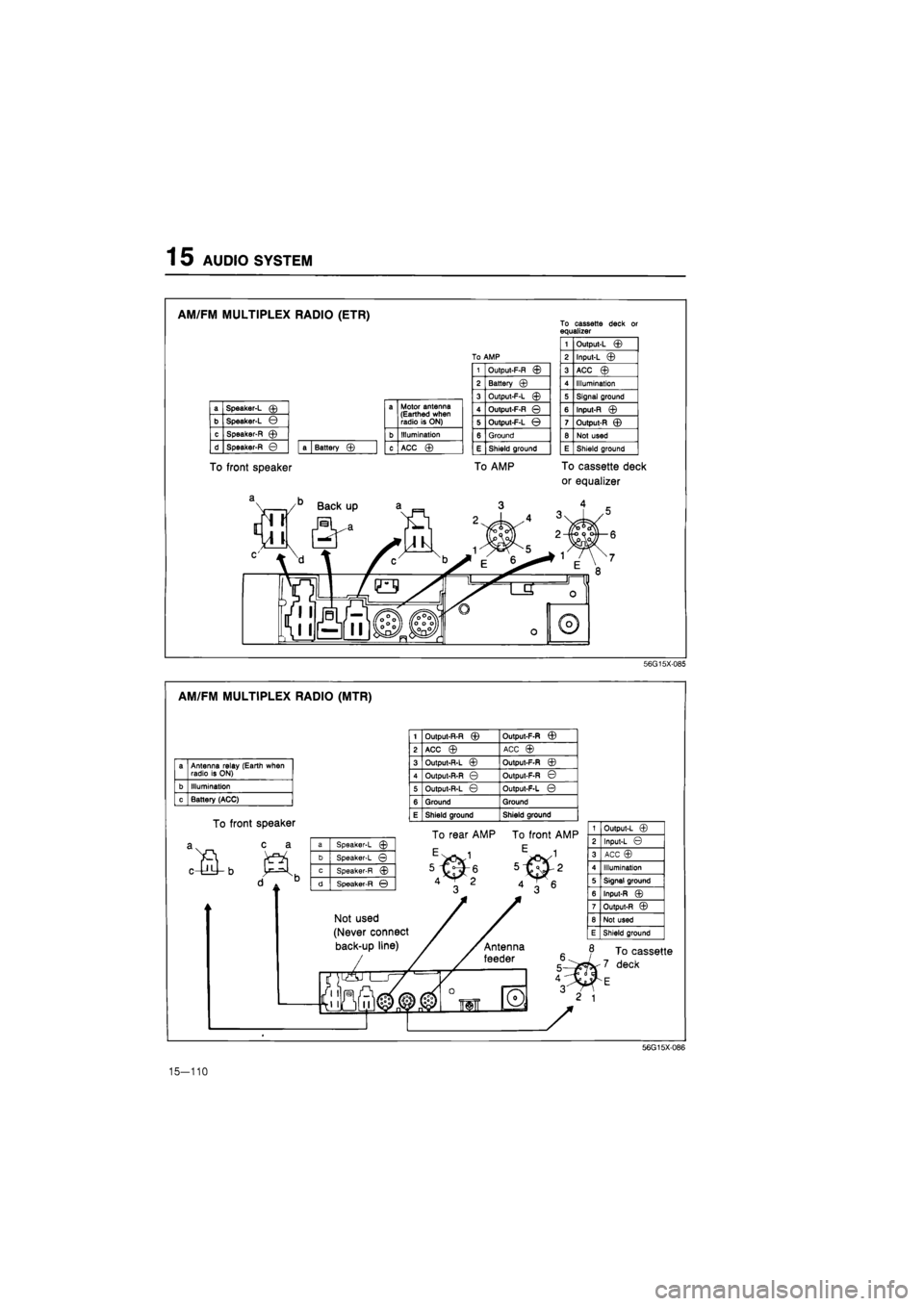
AM/FM MULTIPLEX RADIO (ETR)
To front speaker
To cassette deck or equalizer
a Speaker-L © a Motor antenna (Earthed when radio is ON) b Speaker-L ©
a Motor antenna (Earthed when radio is ON)
c Speaker-R © b Illumination
d Speaker-R © a Battery © c ACC ©
1 Output-L ©
To AMP 2 Input-L ©
1 Output-F-R © 3 ACC ©
2 Battery © 4 Illumination
3 Output-F-L © 5 Signal ground
4 Output-F-R © 6 Input-R ©
5 Output-F-L © 7 Output-R ©
6 Ground 8 Not used
E Shield ground E Shield ground
To AMP To cassette deck
or equalizer
56G15X085
AM/FM MULTIPLEX RADIO (MTR)
a Antenna relay (Earth when radio is ON)
b Illumination
c Battery (ACC)
To front speaker
c a
1 Output-R-R © Output-F-R ©
2 ACC © ACC ©
3 Output-R-L © Output-F-R ©
4 Output-R-R © Output-F-R ©
5 Output-R-L © Output-F-L ©
6 Ground Ground
E Shield ground Shield ground
a Speaker-L ©
b Speaker-L ©
c Speaker-R ©
d Speaker-R ©
To rear AMP To front AMP
Not used
(Never connect
back-up line)
1 Output-L ©
2 Input-L ©
3 ACC ©
4 Illumination
5 Signal ground
6 Input-R ©
7 Output-R ©
8 Not used
E Shield ground
To cassette
deck
56G15X-086
15-110
Page 1766 of 1865
AUDIO SYSTEM 1 5
CASSETTE DECK
To radio
a Antenna relay (Earthed when radio is ON)
b Illumination
c Battery (ACC) ©
Battery (ACC)©
. • Q-
fi0
m
®
jqj
To radio
/
1 Input-L ©
2 Output-L ©
3 Battery (ACC) ©
4 Not used
5 Signal ground
6 Output-R ©
7 Input-R ©
8 Not used
E Shield ground
»
B /1 ^C
a Antenna relay (Earthed when radio is ON)
b Illumination
c Battery (ACC) ©
0
56G15X-088
CASSETTE DECK (SYSTEM 3 AND 4)
To radio
a Power antenna
b Illumination
c Battery (ACC) jm
a Not used
b Not used
c Speaker ©
d Speaker ©
To radio
JHL
a Speaker-L ©
b Speaker-L ©
c Speaker-R ©
d Speaker-R ©
To rear
Blue color
V m.
"T*.
a Power antenna
b Illumination
c Battery (ACC) ©
56G15X-089
15—111
Page 1770 of 1865
AUDIO SYSTEM 1 5
Power Antenna Circuit
86U15X-194
inspection Of Power Antenna Relay
1. Check the voltage at each terminal of the relay con-
nector harness side with each condition.
Terminal Condition Voltage
LW Ignition switch ACC 12V
BY Ignition switch
ON
12V
LgW Ignition switch ACC and radio
power switch
ON
OV
LR Any time 12V
76G15X-096
86U15X-196
If not, repair the harness.
2. Turn the ignition switch on, and check the opera-
tion of the power antenna with each condition.
Condition Antenna operation
GW wire
is
connected
to a
body ground Rises
GW wire
is
not connected to
a
body ground Goes down
If the power antenna does not operate, replace the
power antenna relay or power antenna motor.
15—115
Page 1784 of 1865

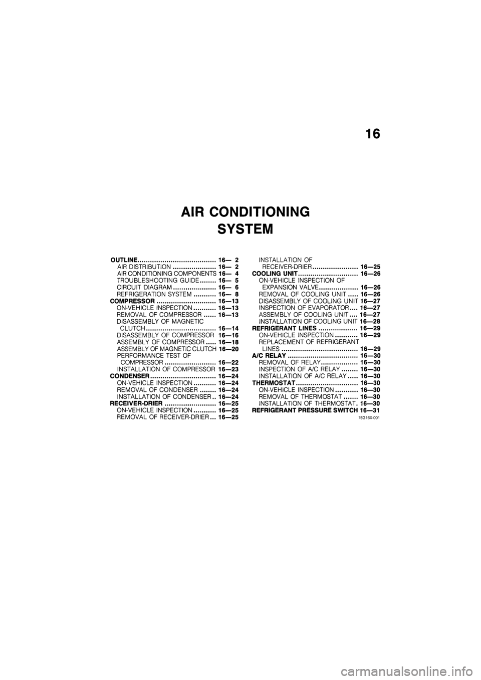
16
AIR CONDITIONING
SYSTEM
OUTLINE 16— 2
AIR DISTRIBUTION 16— 2
AIR CONDITIONING COMPONENTS 16— 4
TROUBLESHOOTING GUIDE 16— 5
CIRCUIT DIAGRAM 16— 6
REFRIGERATION SYSTEM 16— 8
COMPRESSOR 16—13
ON-VEHICLE INSPECTION 16—13
REMOVAL OF COMPRESSOR 16—13
DISASSEMBLY OF MAGNETIC
CLUTCH 16—14
DISASSEMBLY OF COMPRESSOR 16—16
ASSEMBLY OF COMPRESSOR 16—18
ASSEMBLY OF MAGNETIC CLUTCH 16—20
PERFORMANCE TEST OF
COMPRESSOR 16—22
INSTALLATION OF COMPRESSOR 16—23
CONDENSER 16—24
ON-VEHICLE INSPECTION 16—24
REMOVAL OF CONDENSER 16—24
INSTALLATION OF CONDENSER.. 16—24
RECEIVER-DRIER 16—25
ON-VEHICLE INSPECTION 16—25
REMOVAL OF RECEIVER-DRIER... 16—25
INSTALLATION OF
RECEIVER-DRIER 16—25
COOLING UNIT 16—26
ON-VEHICLE INSPECTION OF
EXPANSION VALVE 16—26
REMOVAL OF COOLING UNIT 16—26
DISASSEMBLY OF COOLING UNIT 16—27
INSPECTION OF EVAPORATOR.... 16—27
ASSEMBLY OF COOLING UNIT.... 16—27
INSTALLATION OF COOLING UNIT 16—28
REFRIGERANT LINES 16—29
ON-VEHICLE INSPECTION 16—29
REPLACEMENT OF REFRIGERANT
LINES 16—29
A/C RELAY 16—30
REMOVAL OF RELAY 16—30
INSPECTION OF A/C RELAY 16—30
INSTALLATION OF A/C RELAY 16—30
THERMOSTAT 16—30
ON-VEHICLE INSPECTION 16—30
REMOVAL OF THERMOSTAT 16-30
INSTALLATION OF THERMOSTAT. 16—30
REFRIGERANT PRESSURE SWITCH 16—31
76G16X-001