Page 409 of 1865
4A PTC HEATER SYSTEM
PTC Heater Relay
1. Apply 12V to No. 1 terminal and ground No. 2
terminal).
2. Check for continuity at terminals 3 and 4 with an
ohmmeter.
Operation OV 12V
Terminals 3—4 No continuity Continuity
76G04A-077
4A—44
Page 449 of 1865
4A CONTROL SYSTEM
RELATIONSHIP CHART
O: Related
X
: Not
related
IGNITION COIL
X X
O O O
X
O
X
WATER
THERMO
SWITCH
RADIATOR O O
X X X X
o O WATER
THERMO
SWITCH INTAKE
MANIFOLD o
X X X X
O o
X
VACUUM SWITCH
X X X X X X X
O
IDLE SWITCH
X X
O O O
X X X
A/C SWITCH
X X X X X
O
X X
P/S SWITCH
X X X X X X X X
E/L SWITCHES
/ Headlight Switch
( Rear defroster switch
J
\ Fan speed control switch
/
X X X X X
O
X X
INHIBITOR SWITCH
X X X X X
O O
X
ENGINE CONTROL UNIT
X
o O O O O o O
\
INPUT
DEVICE
AND
ENGINE
CONTROL
UNIT
OUTPUT
DEVICE
PTC
HEATER
CHOKE
OPENER
(FE
and
F8
—
ECE,
Hong
Kong,
&
Singapore)
COASTING
LEANER
COAST
ENRICHMENT
SOLENOID
VALVE
AIR
BYPASS
SOLENOID
VALVE
IDLE-UP
SOLENOID
VALVE
IGNITION
TIMING
CONTROL
SYSTEM
MAIN
AIR
BLEED
CONTROL
SYSTEM
*
FE
8Valve—Unleaded Fuel:
O
(Related)
General and
FE
12Valve—ECE, Hong Kong, Singapore:
X
(Not related)
76G04A-167
4A—84
Page 562 of 1865

4C
FUEL AND EMISSION
CONTROL SYSTEMS
(FUEL INJECTION FE DOHC)
OUTLINE 4C— 2
COMPONENT APPLICATION 4C— 2
SYSTEM DIAGRAM 4C— 3
COMPONENT LOCATION 4C— 4
VACUUM HOSE ROUTING
DIAGRAM 4C— 7
SPECIFICATIONS 4C— 8
TROUBLESHOOTING GUIDE 4C— 9
TROUBLESHOOTING WITH SST.. 4C— 11
INSPECTION PROCEDURE 4C— 12
PRINCIPLE OF CODE CYCLE 4C— 13
CODE NUMBER 4C— 14
SWITCH MONITOR FUNCTION 4C— 25
INSPECTION PROCEDURE 4C— 26
IDLE ADJUSTMENT 4C— 29
IDLE SPEED 4C— 29
IDLE MIXTURE 4C— 30
INTAKE AIR SYSTEM 4C— 31
COMPONENT DESCRIPTION 4C— 31
REMOVAL 4C— 32
PARTS INSPECTION 4C— 33
REPLACEMENT 4C— 36
INSTALLATION 4C— 37
VARIABLE INERTIA CONTROL
(VIC) SYSTEM 4C— 39
COMPONENT DESCRIPTION 4C— 40
TROUBLESHOOTING 4C— 40
IDLE SPEED CONTROL
(ISC) SYSTEM 4C— 44
COMPONENT DESCRIPTION 4C— 45
TROUBLESHOOTING 4C— 46
REMOVAL 4C— 48
FUEL SYSTEM 4C— 49
COMPONENT DESCRIPTION 4C— 50
TROUBLESHOOTING 4C— 51
FUEL PRESSURE RELEASE AND
SERVICING FUEL SYSTEM 4C— 52
MULTI-PRESSURE TESTER 4C— 53
FUEL PUMP 4C— 56
PULSATION DAMPER 4C— 57
INJECTOR 4C— 57
TRANSFER PUMP CONTROL
SYSTEM 4C— 59
REPLACEMENT 4C— 60
FUEL TANK 4C— 65
PRESSURE REGULATOR
CONTROL (PRC) SYSTEM 4C— 68
COMPONENT DESCRIPTION 4C— 69
TROUBLESHOOTING 4C— 69
DECELERATION CONTROL
SYSTEM 4C— 72
COMPONENT DESCRIPTION 4C— 73
TROUBLESHOOTING 4C— 73
ELECTRONIC SPARK ADVANCE
(ESA) CONTROL SYSTEM 4C— 75
COMPONENT DESCRIPTION 4C— 76
TROUBLESHOOTING 4C— 76
EXHAUST GAS RECIRCULATION
(EGR) SYSTEM 4C- 77
COMPONENT DESCRIPTION 4C— 77
TROUBLESHOOTING 4C— 78
EVAPORATIVE EMISSION
CONTROL (EEC) SYSTEM 4C— 80
COMPONENT DESCRIPTION 4C— 80
TROUBLESHOOTING 4C— 81
POSITIVE CRANKCASE
VENTILATION (PCV) SYSTEM.... 4C— 86
COMPONENT DESCRIPTION 4C— 86
PCV VALVE 4C— 86
EXHAUST SYSTEM
(UNLEADED FUEL) 4C— 87
REMOVAL AND INSTALLATION.. 4C— 88
INSPECTION 4C— 88
EXHAUST SYSTEM
(LEADED FUEL) 4C— 89
REMOVAL AND INSTALLATION.. 4C— 90
CONTROL SYSTEM 4C— 91
RELATIONSHIP CHART 4C— 92
EGI MAIN FUSE 4C— 96
CONTROL RELAY 4C— 96
NEUTRAL SWITCH 4C— 97
CLUTCH SWITCH 4C— 97
P/S PRESSURE SWITCH 4C— 97
ENGINE CONTROL UNIT 4C— 98
E/L CONTROL UNIT 4C—102
AIR FLOW SENSOR 4C—103
THROTTLE SENSOR 4C—104
IDLE SWITCH 4C—106
WATER THERMO SWITCH 4C—106
WATER THERMO SENSOR 4C—107
OXYGEN SENSOR 4C—107
DISTRIBUTOR 4C—108
OXYGEN SENSOR HEATER 4C—109
KNOCK SENSOR 4C—109
INTAKE AIR THERMO SENSOR .. 4C—110
76G04C-001
Page 611 of 1865

4C FUEL SYSTEM
COMPONENT DESCRIPTION
Component Function Remark
Air flow sensor Detects amount of intake air;
sends signal to engine control unit
Clutch switch Detects in-gear condition; sends signal to engine control unit Switch ON when clutch pedal released
Engine control unit Detects signals from input sensors and switches; controls injector and fuel pump operations
Fuel filter Filters fuel
Fuel pump Provides fuel to injectors • Operates while engine running
• Installed in fuel tank
Fuel pump control unit (4WS) Monitors fuel level in left section; controls transfer pump operation
G signal pick-up Detects No.1 cylinder TDC; sends signal to engine control unit Installed in distributor
Idle switch Detects when throttle valve fully closed; sends signal to engine control unit Installed on throttle body
Ignition switch (ST position) Sends engine cranking signal to engine control unit
Injector Injects fuel into intake port • Controlled by signals from engine control unit • High-ohmic injector
Intake air thermo sensor Detects intake air temperature; send signal to engine control unit
Control relay Supplies electric current to injectors fuel pump and engine control unit
Ne signal pick-up Detects crank angle at 180° intervals; sends signal to engine control unit Installed in distributor
Neutral switch Detects in-gear condition; sends signal to engine control unit
Switch ON when in gear
Oxygen sensor (Unleaded fuel) Detects oxygen concentration; sends signal to engine control unit
• Zirconia ceramic and platinum coating • Integrated heater coil
Pressure regulator Adjusts fuel pressure supplied to injectors
Pulsation damper Absorbs fuel pulsation
Throttle sensor Detects throttle valve opening angle;
sends signal to engine control unit
Installed on throttle body
Transfer pump (4WS) Pumps fuel from the left to the right side Controlled by fuel pump control unit
Transfer pump switch (4WS) Detects fuel level in left section;
sends signal to control unit
Water thermo sensor Detects coolant temperature; sends signal to engine control unit
Water thermo switch (Unleaded fuel) Detects radiator coolant temperature; sends signal to engine control unit ON: above 17°C (63°F)
76G04C-088
4C-50
Page 662 of 1865

CONTROL SYSTEM 4C
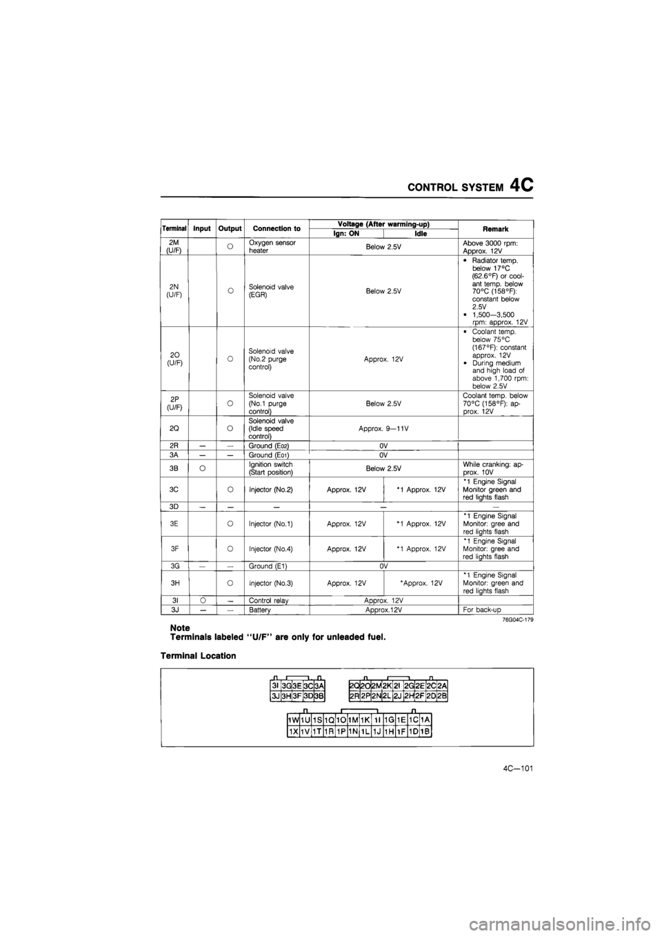
Terminal Input Output Connection to Voltage (After warming-up) Remark Terminal Input Output Connection to Ign: ON Idle Remark
2M
(U/F) o Oxygen sensor
heater Below 2.5V Above 3000 rpm: Approx. 12V
2N
(U/F) o Solenoid valve (EGR) Below 2.5V
• Radiator temp, below 17°C (62.6°F) or cool-ant temp, below 70°C (158°F): constant below 2.5 V
• 1,500-3,500 rpm: approx. 12V
20 (U/F) 0 Solenoid valve (No.2 purge control) Approx. 12V
• Coolant temp, below 75 °C (167°F): constant approx. 12V
• During medium and high load of above 1,700 rpm: below 2.5V
2P
(U/F) o
Solenoid valve
(No.1 purge
control)
Below 2.5V
Coolant temp, below 70°C (158°F): ap-prox. 12V
2Q o Solenoid valve (Idle speed control) Approx. 9—11V
2R — — Ground (E02) OV
3A — — Ground (E01) OV
3B O Ignition switch
(Start position) Below 2.5V While cranking: ap-
Drox. 10V
3C o Injector (No.2) Approx. 12V *1 Approx. 12V
*1 Engine Signal Monitor green and red liahts flash
3D — — — — —
3E o Injector (No.1) Approx. 12V *1 Approx. 12V
*1 Engine Signal
Monitor: gree and
red liahts flash
3F 0 Injector (No.4) Approx. 12V *1 Approx. 12V
*1 Engine Signal Monitor: gree and red liahts flash
3G — Ground (E1) OV
3H o Injector (No.3) Approx. 12V 'Approx. 12V *1 Engine Signal
Monitor: green and
red lights flash
31 0 — Control relav ADDrox. 12V
3J — — Battery Approx. 12V For back-uD
76G04C-179
Note
Terminals labeled "U/F" are only for unleaded fuel.
Terminal Location
31 3G 3E 3C 3A
3J 3H 3F 3D 3B
2Q 2d 2M *
L
CM
2G 2E 2C <
CM
2R 2P 2N 2L 2J 2H 2F 20 2B
1W 1U 1S 1Q 10 1M 1K 11 1G 1E 1C 1A
1X 1V 1T 1R 1P 1N 1L 1J 1H 1F 1D 1B
4C-101
Page 670 of 1865

CONTROL SYSTEM 4C
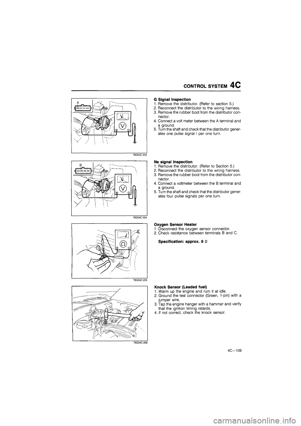
76G04C-203
76G04C-204
76G04C-205
G Signal Inspection
1. Remove the distributor. (Refer to section 5.)
2. Reconnect the distributor to the wiring harness.
3. Remove the rubber boot from the distributor con-
nector.
4. Connect a volt meter between the A terminal and
a ground.
5. Turn the shaft and check that the distributor gener-
ates one pulse signal I per one turn.
Ne signal Inspection
1. Remove the distributor. (Refer to Section 5.)
2. Reconnect the distributor to the wiring harness.
3. Remove the rubber boot from the distributor con-
nector.
4. Connect a voltmeter between the B terminal and
a ground.
5. Turn the shaft and check that the distributor gener-
ates four pulse signals per one turn.
Oxygen Sensor Heater
1. Disconnect the oxygen sensor connector.
2. Check resistance between terminals B and C.
Specification: approx. 6 Q
Knock Sensor (Leaded fuel)
1. Warm up the engine and rum it at idle.
2. Ground the test connector (Green, 1-pin) with a
jumper wire.
3. Tap the engine hanger with a hammer and verify
that the ignition timing retards.
4. If not correct, check the knock sensor.
76G04C-206
4C-109
Page 1624 of 1865
INSTRUMENT PANEL 1 4
INSTRUMENT PANEL
STRUCTURAL VIEW
1. Rear console
2. Upper plate.
3. Front console
4. Glove compartment
5. Side cover
6. Side cover
7. Box
8. Ashtray
9. Center panel
10. Heater control assembly
11. Steering wheel cap
12. Steering wheel
13. Column cover
14. Switch panel
76G14X-036
15. Cap
16. Meter hood
17. Duct
18. Duct and under cover
19. Under cover
20. Duct
21. Meter assembly
22. Instrument panel
14—73
Page 1629 of 1865
1 4 INSTRUMENT PANEL
86U14X-187
86U14X-188
86U14X-189
18. Remove the screws and pull the panel outward.
19. Disconnect the connectors and remove the switch
panel.
20. Remove the screws and remove the glove box.
21. Disconnect the glove box light connector.
22. Remove the center panel.
23. Remove the screws and slide out the heater con-
trol assembly.
24. Disconnect the control wires at the DEF, MAX-
COLD and REC positions (lever type control).
Note
Disconnect the connectors at the rear of the
control (Logicon type).
25. Remove the center cap.
26. Remove the instrument panel mounting bolt.
86U14X-190
14-78