Page 1631 of 1865

14 INSTRUMENT PANEL
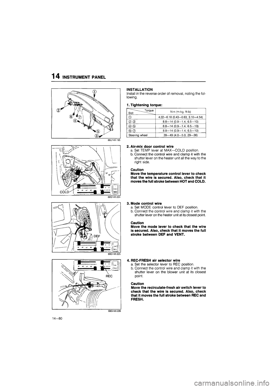
INSTALLATION
Install in the reverse order of removal, noting the fol-
lowing.
1. Tightening torque:
.^Torque Bolt
N-m (m-kg,
ft-lb)
©
4.22-6.18 (0.43-0.63, 3.10-4.54)
®(D
8.8-14 (0.9—1.4, 6.5—10)
©(D
8.8—14 (0.9—1.4, 6.5—10)
©@
8.8-14 (0.9-1.4, 6.5-10)
Steering wheel 39-49 (4.0—5.0, 29—36)
86U14X-195
2. Air-mix door control wire
a. Set TEMP lever at MAX—COLD position.
b. Connect the control wire and clamp it with the
shutter lever on the heater unit all the way to the
right side.
Caution
Move the temperature control lever to check
that the wire is secured. Also, check that it
moves the full stroke between HOT and COLD.
69G14X-224
3. Mode control wire
a. Set MODE control lever to DEF position.
b. Connect the control wire and clamp it with the
shutter lever on the heater unit at its closest point.
Caution
Move the mode lever to check that the wire
is secured. Also, check that it moves the full
stroke between DEF and VENT.
69G14X-225
, REC-FRESH air selector wire
a. Set the selector lever to REC position.
b. Connect the control wire and clamp it with the
shutter lever on the blower unit at its closest
point.
Caution
Move the recirculate-fresh air switch lever to
check that the wire is secured. Also, check
that it moves the full stroke between REC and
FRESH.
69G14X-226
14—80
Page 1656 of 1865

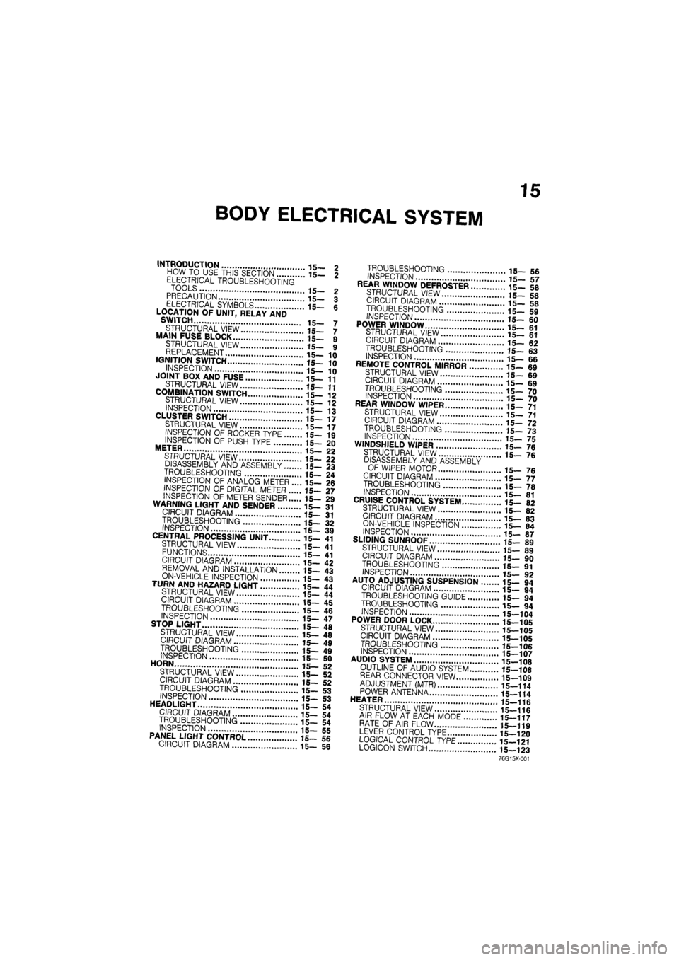
15
BODY ELECTRICAL SYSTEM
INTRODUCTION 15- 2 HOW TO USE THIS SECTION 15— 2 ELECTRICAL TROUBLESHOOTING TOOLS 15- 2 PRECAUTION 15— 3 ELECTRICAL SYMBOLS 15- 6 LOCATION OF UNIT, RELAY AND SWITCH 15- 7
STRUCTURAL VIEW 15— 7 MAIN FUSE BLOCK 15- 9 STRUCTURAL VIEW 15— 9 REPLACEMENT 15—10 IGNITION SWITCH 15—10
INSPECTION 15— 10 JOINT BOX AND FUSE 15—11
STRUCTURAL VIEW 15—11
COMBINATION SWITCH 15-12 STRUCTURAL VIEW 15- 12 INSPECTION 15— 13 CLUSTER SWITCH 15—17 STRUCTURAL VIEW 15— 17 INSPECTION OF ROCKER TYPE 15— 19
INSPECTION OF PUSH TYPE 15— 20 METER 15— 22 STRUCTURAL VIEW 15— 22 DISASSEMBLY AND ASSEMBLY 15— 23
TROUBLESHOOTING 15— 24 INSPECTION OF ANALOG METER .... 15— 26 INSPECTION OF DIGITAL METER 15— 27
INSPECTION OF METER SENDER 15— 29 WARNING LIGHT AND SENDER 15- 31 CIRCUIT DIAGRAM 15— 31
TROUBLESHOOTING 15- 32 INSPECTION 15— 39 CENTRAL PROCESSING UNIT 15— 41 STRUCTURAL VIEW 15— 41 FUNCTIONS 15- 41 CIRCUIT DIAGRAM 15— 42 REMOVAL AND INSTALLATION 15— 43
ON-VEHICLE INSPECTION 15- 43 TURN AND HAZARD LIGHT 15- 44 STRUCTURAL VIEW 15— 44 CIRCUIT DIAGRAM 15— 45
TROUBLESHOOTING 15- 46 INSPECTION 15— 47 STOP LIGHT 15— 48
STRUCTURAL VIEW 15— 48 CIRCUIT DIAGRAM 15— 49
TROUBLESHOOTING 15- 49 INSPECTION 15- 50 HORN 15— 52 STRUCTURAL VIEW 15— 52 CIRCUIT DIAGRAM 15— 52 TROUBLESHOOTING 15— 53 INSPECTION 15-53 HEADLIGHT 15— 54 CIRCUIT DIAGRAM 15— 54 TROUBLESHOOTING 15— 54 INSPECTION 15— 55 PANEL LIGHT CONTROL 15— 56 CIRCUIT DIAGRAM 15— 56
TROUBLESHOOTING 15_ 5fi INSPECTION 17 REAR WINDOW DEFROSTER ..i".'! 15- 58
STRUCTURAL VIEW 15-5fl CIRCUIT DIAGRAM 15_ «
TROUBLESHOOTING '.. 15_ 59
INSPECTION
15-60 POWER WINDOW 15-61 STRUCTURAL VIEW il_ «1 CIRCUIT DIAGRAM 15_ 62 TROUBLESHOOTING 15- «3 INSPECTION 15-66 REMOTE CONTROL MIRROR ........15- 69 STRUCTURAL VIEW 15-69 CIRCUIT DIAGRAM 15_ 69
TROUBLESHOOTING 15_ 70 INSPECTION 15_ 70 REAR WINDOW WIPER 15_ 71 STRUCTURAL VIEW 15-71 CIRCUIT DIAGRAM .'.'.'...' 15_ 72
TROUBLESHOOTING 15-73 INSPECTION 15-75 WINDSHIELD WIPER 15-76 STRUCTURAL VIEW ' ' 15— 7e
DISASSEMBLY AND ASSEMBLY OF WIPER MOTOR 15_ 76 CIRCUIT DIAGRAM 15-77 TROUBLESHOOTING " " 15— 70 INSPECTION 15-81 CRUISE CONTROL SYSTEM 15- 82 STRUCTURAL VIEW 15-82 CIRCUIT DIAGRAM 15-83 ON-VEHICLE INSPECTION \..\m 15- 84 INSPECTION 15-87 SLIDING SUNROOF 15-89 STRUCTURAL VIEW 15_ 89 CIRCUIT DIAGRAM i5_ 90
TROUBLESHOOTING 15— 91 INSPECTION 15_ 90 AUTO ADJUSTING SUSPENSION 15— 94
CIRCUIT DIAGRAM 15- 94
TROUBLESHOOTING GUIDE 15— 94
TROUBLESHOOTING 15— 94
INSPECTION 15-104
POWER DOOR LOCK 15-105
STRUCTURAL VIEW 15-105
CIRCUIT DIAGRAM 15-105
TROUBLESHOOTING 15-106 INSPECTION 15-107 AUDIO SYSTEM " 15_108 OUTLINE OF AUDIO SYSTEM 15-108 REAR CONNECTOR VIEW 15-109 ADJUSTMENT (MTR) 15—114 POWER ANTENNA 15-114 HEATER J
STRUCTURAL VIEW 15-116 AIR FLOW AT EACH MODE 15-117 RATE OF AIR FLOW 15-119 LEVER CONTROL TYPE 15-120 LOGICAL CONTROL
TYPE
15—121 LOGICON SWITCH 15—123
76G15X-001
Page 1661 of 1865
15 INTRODUCTION
ELECTRICAL SYMBOLS
Switches and Relays
There is an NC (normally closed) and NO (normally open) indication for switches and relays; this indi-
cates the condition when there has been no change of operating conditions.
Relay
NO type relay NC type relay
Switch
NO switch NC switch
Not
in
operation (No power supply)
—Jtfiifij —o o—
Flow Stop Flow
In operation (Power supply)
^
^aijuiy—'
Flow
l=3X
Stop
Flow
Stop
Other Electrical Symbols
Holder
Box —
© ©
Holder
Box —
Holder
Box —
BATTERY BODY GROUND FUSE FUSIBLE LINK
(£)
* 1 fc
MOTOR COIL, SOLENOID RESISTOR VARIABLE RESISTOR
1
ii
-L ©
THERMISTER DIODE CONDENSER LIGHT
1
TRANSISTOR SPEAKER CIGARETTE LIGHTER HEATER
69G15X-009
15—6
Page 1663 of 1865
1 5 LOCATION OF UNIT, RELAY AND SWITCH
STRUCTURAL VIEW
Hatchback
Light and turn switch
Rear wiper switch
Rear washer switch
Front wiper and washer
switch, and cruise control switch
/ Hazard switch (Except RHD model)
Rear def. switch (Except ECE)
Rear fog light switch (For ECE)
AAS switch
Headlight cleaner switch
Remote control mirror switch
Heater control switch
Driving mode selector switch
Cruise control main switch
Coupe/MX-6 and Sedan
-nr
J
nu
iTPD'i
Rear def, switch (Except ECE) Hazarc
Rear fog light switch (For ECE)
switch (Except RHD model)
15-8
86U15X-003
Page 1664 of 1865
MAIN FUSE BLOCK
1
5
MAIN FUSE BLOCK
STRUCTURAL VIEW
LHD
and RHD
General, Middle East,
ECE
(Carburetor model)
0
U
%
s
5
»
00000 USE
THE
DESIGNATED FUSE ONLY
ECE
(EGI
model)
£
o 2Z
o u
^ *5
4
-
<
—
o
O
n
2
O
<
a
HI
<
°
I®
a
o
o-S
Ul
51 Ui
^
tB USE
THE
DESIGNATED FUSE ONLY
>1
P
West Germany (Carburetor
and EGI
model)
Q
o o
^
*S
lu
u
<
EL
°
33 JZ< gis
2 ? «
Q-
o
S3 ill
™
N
TiSE
THE
DESIGNATED
FU
Unleaded fuel model
(EGI)
USE
THE
DESIGNATED FUSE ONLY
PTC
30A
(Sweden)
HEAD
40A
(Sweden)
BTN
40A
(Sweden)
LHD
and RHD
General,
ECE
(Diesel model) Except Sweden
1 T
1
•N
HEATER
[
40A (COOLING FAN
[
30A
z
<
m
3
MAIN
BOA
;
/I
HEAD
40A
ADD
FAN 30A
/ xx
West Germany (Diesel model)
fl
,
v
K
<
t
o
,o
,
p <
f—
o
0.
o
86U15X-004
15—9
Page 1771 of 1865
15 HEATER
HEATER
STRUCTURAL VIEW
15—116
Page 1772 of 1865
HEATER 15
AIR FLOW AT EACH MODE
VENT mode
Type A
86U15X-198
BI-LEVEL mode
Type A
Type B
dS O CD • • CJ C3 W <& W G) • T3 A/C - EOON
| cn ES^GJJCRJ A EIZI czi tzzi |
I 11 (—HI—
86U15X-199
15-117
Page 1773 of 1865
15 HEATER
HEAT mode
Type A
In ECO i
Type B
[E
C3 <=> C3 A.'C - ECGN
CO f—7WZZ3 CZ) CO CZ) * OFP^ i a 3
i Ml" Warm air
86U15X-200
HEAT/DEF mode
Type A
i i; ii—innnnnni
-V v-y
^ ca ° H
OP »OFF 1_2_ 3 4
h- —
[aTC]
In ECO |
Type B
CD CD C3 E3 C3 -J W <3/ ® CD E3 cS> Si CD CD A/C - ECON
[ IZZ1 IZZI CZI Ci|pzi CO CN I
i nr
Jr df^i a 3 a
(—Ki— Warm air
86U15X-201
15—118