Page 1782 of 1865

HEATER 15
f! !"H
a
+
1 d-V' X /
S3
Voltmeter
86U15X-222
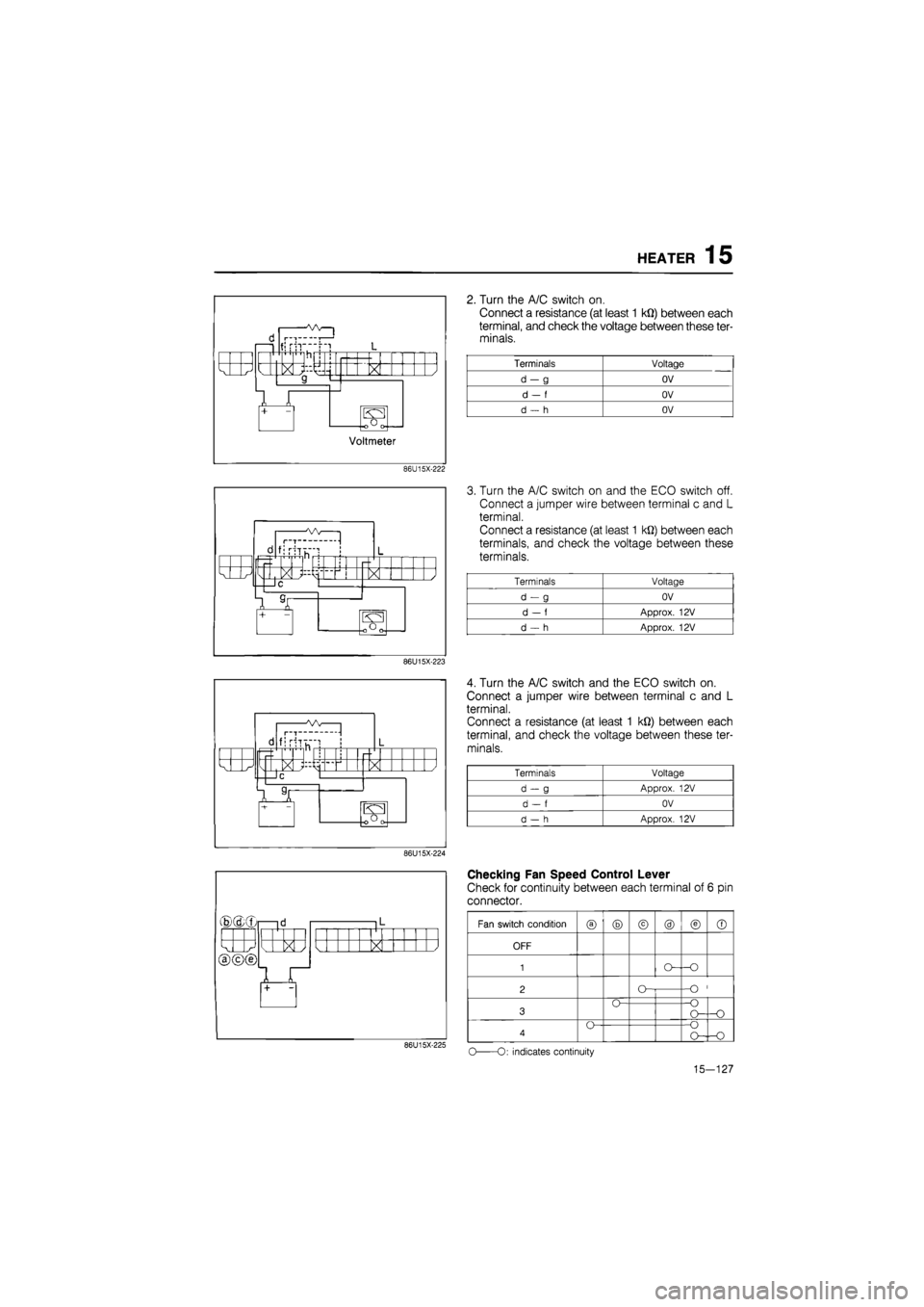
2. Turn the A/C switch on.
Connect a resistance (at least 1 kQ) between each
terminal, and check the voltage between these ter-
minals.
Terminals Voltage
d-g OV
d
- f
OV
d
- h
OV
d I—T-
fjrh
X }
®(dxr
X /
86U15X-223
d fi riTu~"! 1 L r-
k J M > < / —IC
7 T — 101 [oOrv
86U15X-224
X
86U15X-225
3. Turn the A/C switch on and the ECO switch off.
Connect a jumper wire between terminal c and L
terminal.
Connect a resistance (at least 1 kQ) between each
terminals, and check the voltage between these
terminals.
Terminals Voltage
d-g OV
d
- f
Approx.
12V
d
- h
Approx.
12V
4. Turn the A/C switch and the ECO switch on.
Connect a jumper wire between terminal c and L
terminal.
Connect a resistance (at least 1 kQ) between each
terminal, and check the voltage between these ter-
minals.
Terminals Voltage
d-g Approx.
12V
d
- f
OV
d
- h
Approx.
12V
Checking Fan Speed Control Lever
Check for continuity between each terminal of 6 pin
connector.
Fan switch condition
® ® © @ © ©
OFF
1
2 O--O
3 O--O O— -O
4 O--O O--O
o
-O: indicates continuity
15-127
Page 1783 of 1865
15 HEATER
i l< i |l
k J X / X X L<
1 +
L<
1 + 1
Checking Dim Indicator Circuits
(Indicator circuit)
1. Connect a jumper wire-between terminal c and ter-
minal L.
Check for illumination at A/C switch indicator with
A/C switch on.
Check for illumination at ECO switch indicator with
ECO switch on.
86U15X-226
d 1 |L
k J X / I k
1 Jl +
2. Check that the mode control switch and REC-
FRESH select switch indicators when the respec-
tive switches ON.
86U15X-227
3. Apply 12V to terminal a, and check that the indi-
cators are dim.
86U15X-228
b —id 1 L
1 1 j
k XI N_ > < / a
ir
Checking Illumination Circuit
1. Connect a jumper wire between terminal b and ter-
minal L.
2. Apply 12V to terminal a, and check that the indi-
cators are dim.
86U15X-229
15-128
Page 1811 of 1865
1 6 COOLING UNIT
INSTALLATION OF COOLING UNIT
1. Install the cooling unit by using the two nuts.
Note
Adjust and position the unit so that its con-
nections match those of the heater unit and
the blower unit.
2. Connect the drain hose.
76G16X-625
Sealing plate
Heater I _ .. ' . . - V
unit Evaporator dealing plate Blower unit
3. Join the connections on both sides by using the
seal plates.
4. Connect the A/C harness to the cooling unit.
76G16X-626
76G16X-627
5. Connect the liquid line high-pressure pipe and suc-
tion low-pressure pipe to the cooling unit.
Tightening torque:
15—22 Nm (1.5—2.5 m-kg, 11—18 ft-lb)
6. Install the instrument lower panel, shower duct and
glove box.
7. If the evaporator is replaced, add compressor oil
to the compressor.
Compressor oil: 50 cc (3.05 cu in)
16-28
Page 1830 of 1865

30 TECHNICAL DATA
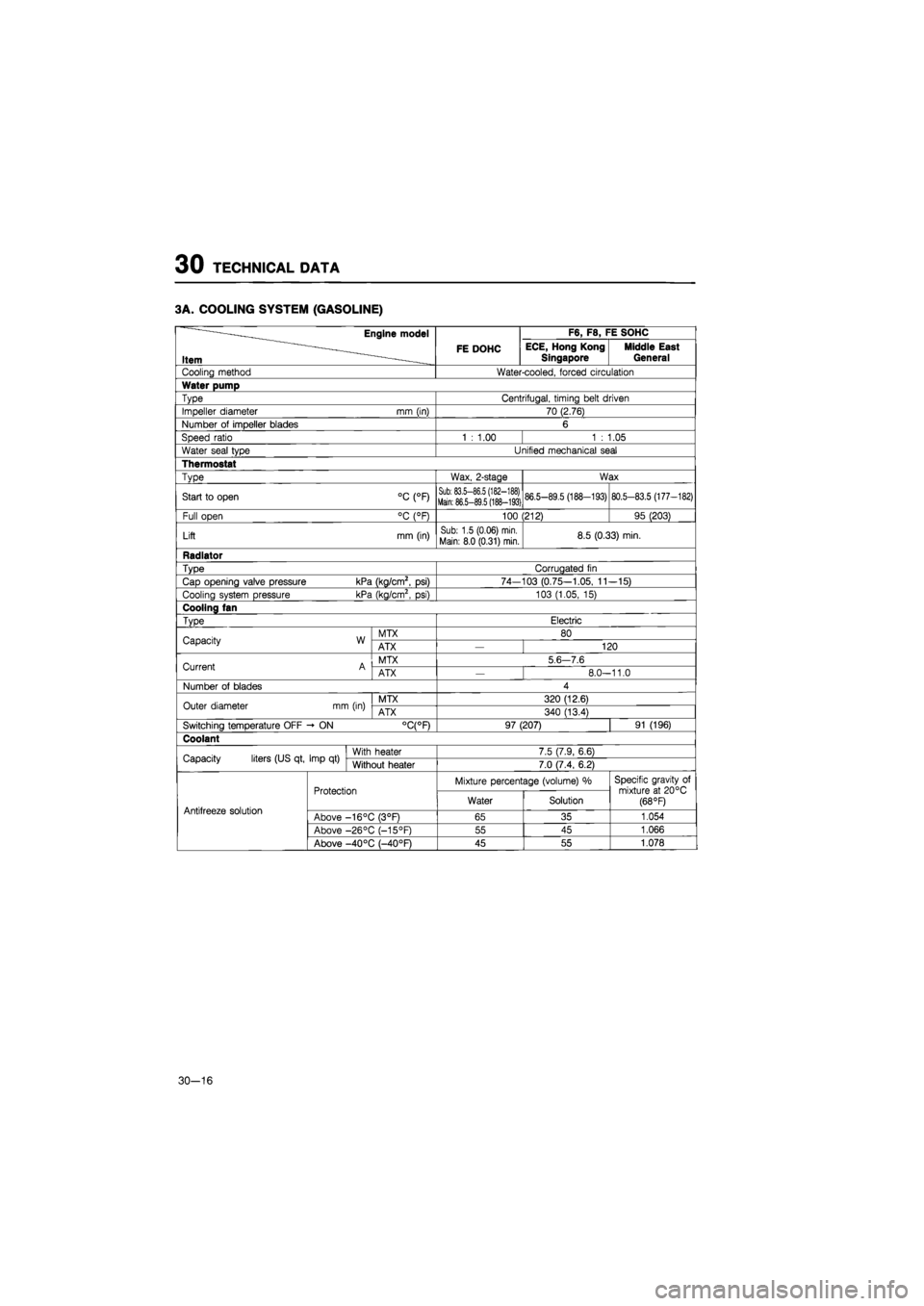
3A. COOLING SYSTEM (GASOLINE)
Engine model F6, F8, FE SOHC
Item FE DOHC ECE, Hong Kong
Singapore Middle East General
Cooling method Water-cooled, forced circulation
Water pump
Type Centrifugal, timing belt driven
Impeller diameter mm (in) 70 (2.76)
Number
of
impeller blades 6
Speed ratio 1
:
1.00 1
:
1.05
Water seal type Unified mechanical seal
Thermostat
Type Wax, 2-stage Wax
Start
to
open °C (°F) Sub: 83.5-86.5 (182-188) Main: 86.5-89.5 (188-193) 86.5-89.5 (188-193) 80.5-83.5 (177-182)
Full open °C (°F) 100 (212) 95 (203)
Lift mm (in) Sub: 1.5 (0.06) min.
Main: 8.0 (0.31) min. 8.5 (0.33) min.
Radiator
Type Corrugated
fin
Cap opening valve pressure kPa (kg/cm2,
psi)
74-103 (0.75-1.05,
11
-15)
Cooling system pressure kPa (kg/cm2,
psi)
103 (1.05,
15)
Cooling fan
Type Electric
Capacity W MTX 80 Capacity W ATX 120
Current A MTX 5
6 7.6
Current A ATX
—
8.0-11.0
Number
of
blades 4
Outer diameter mm (in) MTX 320 (12.6) Outer diameter mm (in) ATX 340 (13.4)
Switching temperature OFF -
ON
°C(°F) 97 (207) 91 (196)
Coolant
Capacity liters (US qt, Imp
qt)
With heater 7.5 (7.9, 6.6) Capacity liters (US qt, Imp
qt)
Without heater 7.0 (7.4, 6.2)
Protection Mixture percentage (volume)
%
Specific gravity
of
mixture
at
20°C (68 °F) Antifreeze solution
Protection Water Solution
Specific gravity
of
mixture
at
20°C (68 °F) Antifreeze solution Above -16°C (3°F) 65 35 1.054
Above -26°C (-15°F) 55 45 1.066
Above -40 °C (—40°F) 45 55 1.078
30-16
Page 1831 of 1865

TECHNICAL DATA 30
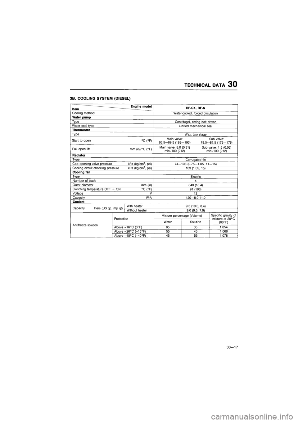
3B. COOLING SYSTEM (DIESEL)
Item Engine model RF-CX, RF-N
Cooling method Water-cooled, forced circulation
Water pump
Type Centrifugal, timing belt driven
Water seal type Unified mechanical seal
Thermostat
Type Wax, two stage
Start
to
open °C (°F) Main valve:
86.5-89.5 (188-193)
78.5-
Sub valve: 81.5 (173-179)
Full open lift mm (in)/°C (°F) Main valve: 8.0 (0.31) Sub valve: 1.5 (0.06) min./100 (212) min./100 (212)
Radiator
Type Corrugated
fin
Cap opening valve pressure kPa (kg/cm2,
psi)
74—103 (0.75—1.05,
11
-15)
Cooling circuit checking pressure kPa (kg/cm2,
psi)
103 (1.05,
15)
Cooling fan
Type Electric
Number
of
blade 4
Outer diameter mm (in) 340 (13.4)
Switching temperature OFF -»
ON
°C (°F) 91 (196)
Voltage V 12
Capacity W-A 120-8.0-11.0
Coolant
Capacity liters (US qt, Imp
qt)
With heater 9.5 (10.0, 8.4) Capacity liters (US qt, Imp
qt)
Without heater 9.0 (9.5, 7.9)
Protection Mixture percentage (Volume) Specific gravity
of
mixture
at
20°C (68 °F) Antifreeze solution
Protection Water Solution
Specific gravity
of
mixture
at
20°C (68 °F) Antifreeze solution Above -16°C (3°F) 65 35 1.054
Above -26°C (-15°F) 55 45 1.066
Above -40°C (-40°F) 45 55 1.078
30-17