Page 768 of 1865

5 STARTER (DIESEL ENGINE, 2.0 KW TYPE)
4BG05X-082
4BG05X-103
Faulty repair
Bad Good
Mica
Undercut
Segments
4BG05X-084
2. Vibration of the commutator
(1) Place the armature on V blocks, and measure
the vibration by using a dial gauge.
(2) If the vibration is Limit or more, repair so that
it becomes standard by using a lathe, or re-
place the armature.
Standard vibration: 0.05 mm (0.002 in)
Limit: 0.4 mm (0.018 in)
Note
Before checking, be sure that there is no play
in the bearings.
3. Outer diameter of the commutator
Replace the armature if the outer diameter of the
commutator is grind limit or less.
4. Roughness of the commutator surface
(1) If the commutator surface is dirty, wipe it with
a cloth.
(2) If it is rough, repair it by using a lathe or fine
sandpaper.
Grind limit: 34 mm (1.34 in)
5. Segment groove depth
If the depth of the mold between segments is limit
depth or less, undercut the grooves by standard
depth.
Standard depth:
0.5—0.8 mm (0.020—0.031 in)
Limit depth: 0.2 mm (0.008 in)
Field Coil
1. Wiring damage
(1) Check for continuity between the connector
and brushes by using a circuit tester.
(2) Replace the yoke assembly if there is no con-
tinuity.
4BG05X-085
5-62
Page 769 of 1865
STARTER (DIESEL ENGINE, 2.0 KW TYPE) 5
4BG05X-086
4BG05X-087
4BG05X-088
2. Ground of the field coil
(1) Check for continuity between the connector
and yoke by using a circuit tester.
(2) Repair, or replace the yoke assembly if there
is continuity.
3. Installation of the field coil
Replace the yoke assembly
if
the field coil is loose.
Brush and Brush Holder
1. Brush
If the brushes are worn beyond the wear limit, or
if the wear is near the limit, replace the brushes.
Standard: 17 mm (0.669 in)
Wear limit: 11 mm (0.433 in)
2. Brush spring
(1) Measure the force of the brush spring by us-
ing a spring balance.
(2) Replace the brush spring if the force is limit or
less.
Limit: 9 N (900 g, 31.75 oz)
3. Brush holder
(1) Check for continuity between the insulated
brush and the plate by using a circuit tester.
(2) Repair or replace if there is continuity.
(3) Also check to be sure that the brush slides
smoothly inside the brush holder.
4BG05X-089
5-63
Page 770 of 1865

5 STARTER (DIESEL ENGINE, 2.0 KW TYPE)
Suitable _
steel plate
Armature
4BG05X-104
4BG05X-092
4BG05X-093
Bearing
Check for abnormal noise, looseness, insufficient
lubrication, etc. Replace the bearing if there is any
abnormality.
Take out the bearing, as shown in the figure, by us-
ing the suitable tools.
PERFORMANCE INSPECTION
Magnetic Switch
Disconnect the terminal M wire, and make the fol-
lowing tests.
Pull-in Test
The switch is normal
if
the pinion ejects outward when
the battery is connected as shown in the figure.
Caution
Do not supply power continuously for more
than 10 seconds.
Hold-in Test
1. After completing the pull-in test, disconnect the wire
from terminal M (with the pinion left ejected).
2. The hold-in coil is functioning properly if the pin-
ion does not return.
Return Test
1. Connect the battery between terminal M of the
magnetic switch and the body, as shown in the
figure.
2. Pull the pinion out manually to the pinion stopper
position.
3. The pinion should immediately return to its origi-
nal position when it is released.
4BG05X-094
5—64
Page 772 of 1865
5 STARTER (DIESEL ENGINE, 2.0 KW TYPE)
STARTER (DIESEL
ENGINE, 2.2
KW TYPE)
STARTING SYSTEM CIRCUIT
4BG05X-106
76G05X-060
ON-VEHICLE INSPECTION
Charge the battery fully before starting the following
inspections.
A. If the magnetic switch dose not function dur-
ing starting.
1. Turn the ignition switch to the start position.
2. Measure the voltage between the S terminal and
ground.
3.
If
the measured value is standard voltage or more,
there is starter malfunction.
4. If it is less than standard voltage, there is a mal-
function in the wiring.
Standard voltage: 8 V
Caution
If the magnetic switch is hot, it may not func-
tion even though the voltage is standard volt-
age or more.
B.lf the starter won't crank, or if the cranking
speed is slow.
The problem may be a malfunction of the starter
or in the wiring.
Note
The cranking speed is greatly affected by the
viscosity of the engine oil.
5—66
Page 777 of 1865

STARTER (DIESEL ENGINE, 2.2 KW TYPE) 5
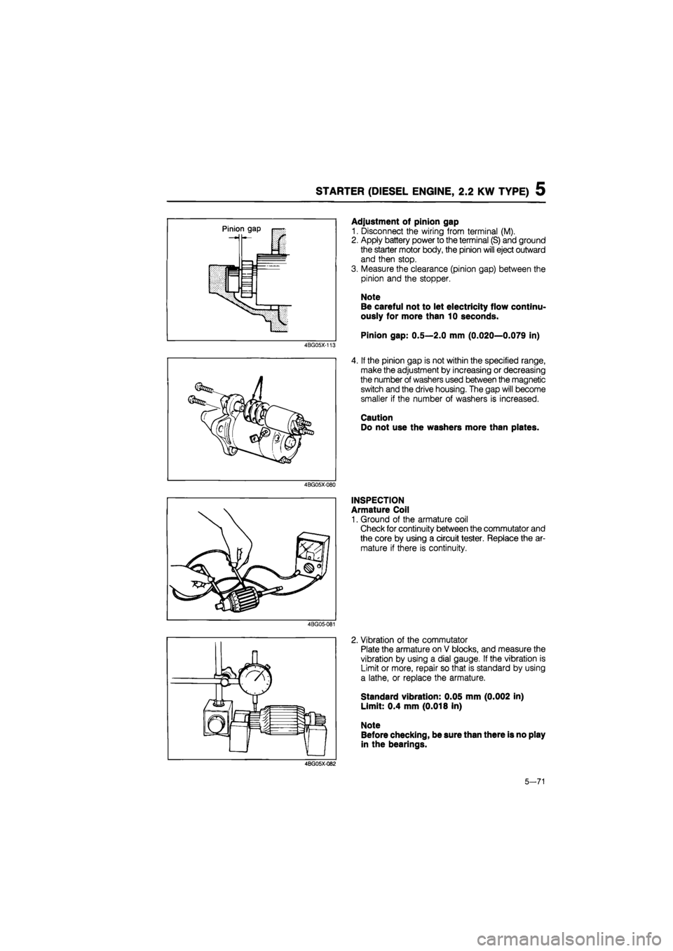
4BG05X-113
4BG05X-080
Adjustment of pinion gap
1. Disconnect the wiring from terminal (M).
2. Apply battery power to the terminal (S) and ground
the starter motor body, the pinion will eject outward
and then stop.
3. Measure the clearance (pinion gap) between the
pinion and the stopper.
Note
Be careful not to let electricity flow continu-
ously for more than 10 seconds.
Pinion gap: 0.5—2.0 mm (0.020—0.079 in)
4. If the pinion gap is not within the specified range,
make the adjustment by increasing or decreasing
the number of washers used between the magnetic
switch and the drive housing. The gap will become
smaller if the number of washers is increased.
Caution
Do not use the washers more than plates.
INSPECTION
Armature Coil
1. Ground of the armature coil
Check for continuity between the commutator and
the core by using a circuit tester. Replace the ar-
mature if there is continuity.
4BG05-081
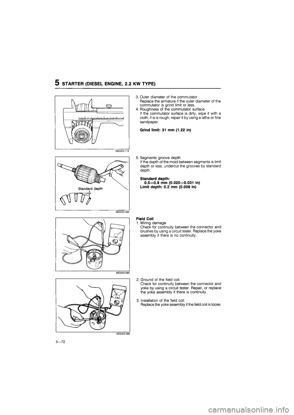
2. Vibration of the commutator
Plate the armature on V blocks, and measure the
vibration by using a dial gauge. If the vibration is
Limit or more, repair so that is standard by using
a lathe, or replace the armature.
Standard vibration: 0.05 mm (0.002 in)
Limit: 0.4 mm (0.018 in)
Note
Before checking, be sure than there is no play
in the bearings.
4BG05X-Q82
5-71
Page 778 of 1865

5 STARTER (DIESEL ENGINE, 2.2 KW TYPE)
4BG05X-115
4BG05X-085
3. Outer diameter of the commutator
Replace the armature if the outer diameter of the
commutator is grind limit or less.
4. Roughness of the commutator surface
If the commutator surface is dirty, wipe it with a
cloth; if is is rough, repair it by using a lathe or fine
sandpaper.
Grind limit: 31 mm (1.22 in)
5. Segments groove depth
If the depth of the mold between segments is limit
depth or less, undercut the grooves by standard
depth.
Standard depth:
0.5—0.8 mm (0.020—0.031 in)
Limit depth: 0.2 mm (0.008 in)
Field Coil
1. Wiring damage
Check for continuity between the connector and
brushes by using a circuit tester. Replace the yoke
assembly if there is no continuity.
2. Ground of the field coil
Check for continuity between the connector and
yoke by using a circuit tester. Repair, or replace
the yoke assembly if there is continuity.
3. Installation of the field coil
Replace the yoke assembly
if
the field coil is loose.
4BG05X-086
5-72
Page 781 of 1865

5 STARTER (DIESEL ENGINE, 2.0 KW TYPE)
Hold-in Test
1. After completing the pull-in test, disconnect the wire
from terminal M (with the pinion left ejected).
2. The hold-in coil is functioning properly if the pin-
ion does not return.
4BG05X-093
Return Test
1. Connect the battery between terminal M of the
magnetic switch and the body, as shown in the
figure.
2. Pull the pinion out manually to the pinion stopper
position.
3. The pinion should immediately return to its origi-
nal position when it is released.
4BG05X-094
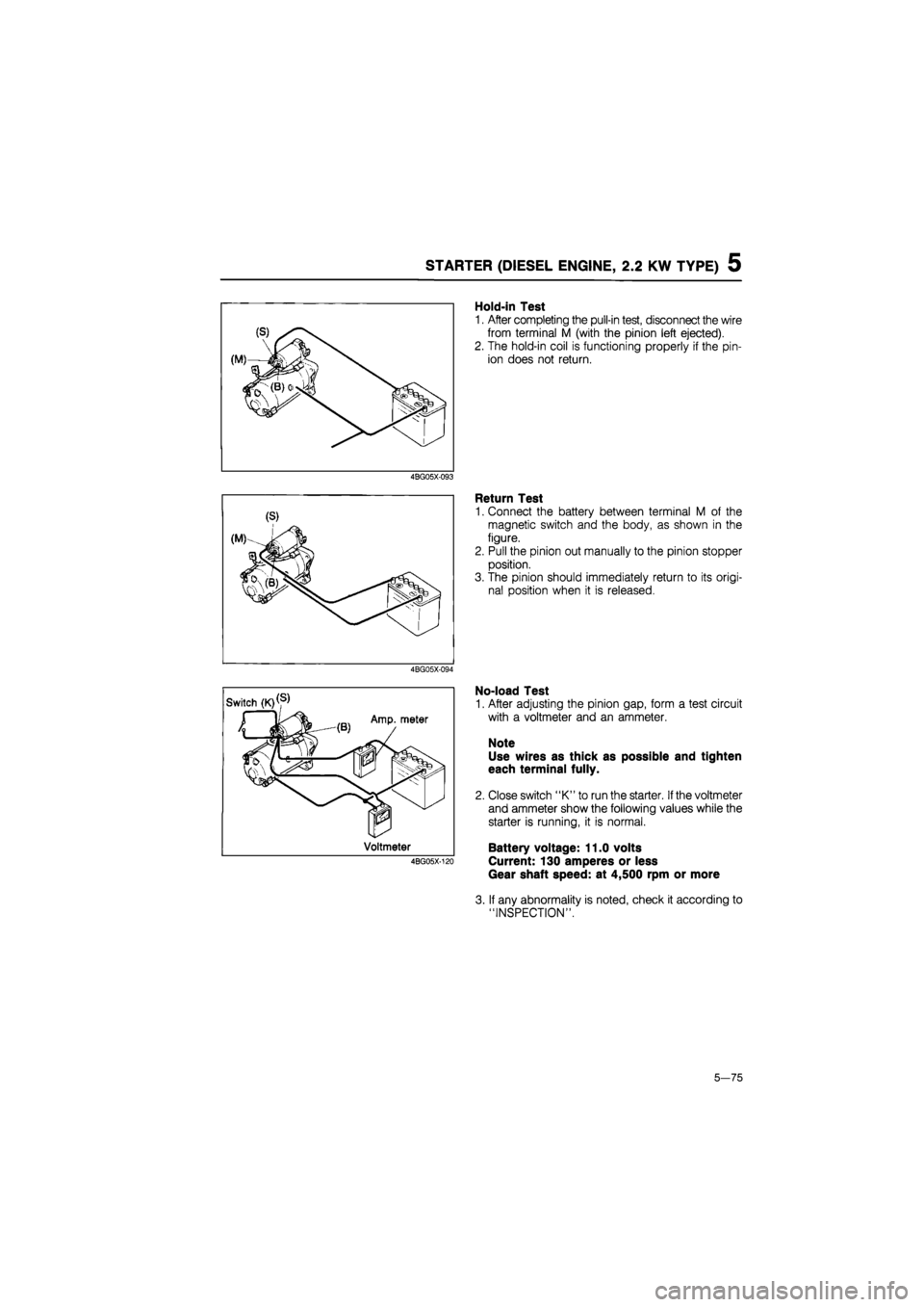
No-load Test
1. After adjusting the pinion gap, form a test circuit
with a voltmeter and an ammeter.
Note
Use wires as thick as possible and tighten
each terminal fully.
2. Close switch "K" to run the starter.
If
the voltmeter
and ammeter show the following values while the
starter is running, it is normal.
Battery voltage: 11.0 volts
Current: 130 amperes or less
Gear shaft speed: at 4,500 rpm or more
3. If any abnormality is noted, check it according to
"INSPECTION".
5—75
Page 789 of 1865

TROUBLESHOOTING GUIDE 6
SPECIFICATIONS
Item Engine model F6 F8 FE FE DOHC RF-N RF-CX
Clutch control type Hydraulic
Clutch cover type Diaphragm spring
General 3,434
(350,770) 3,846
(392,862) 4,316 (440,968) 3,846
(392,862) —
Set load
N (kg, lb) ECE (Except UK) — 4,022
(410,902) 4,611 (470, 1,034) 4,022 (410, 902)
UK — 3,846
(392,862)
4,611 (470,1,034) 4,316
(440,968)
3,846 (392,862) 4,022 (410,902)
Clutch disc Outer diameter mm (in) 200 (7.874) 215 (8.465) 225 (8.858)
Inner diameter mm (in) 130 (5.118) 150 (5.906)
Pressure plate side
General 4.1 (0.16) —
Thickness Pressure plate side
ECE
(Except UK) — 3.8 (0.15)
mm(in)
Pressure plate side UK 4.1 (0.16)13.8 (0.15) 4.1 (0.16) 3.8 (0.15)
Flywheel side 3.5 (0.14)
Type Suspended
Pedal ratio LHD 6.00
Clutch pedal Pedal ratio RHD 5.96
Full stroke mm (in) 135 (5.31)
Height mm (in) 216.5-221.5 (8.524-8.720)
Master cylinder inner diameter mm (in) 15.87 (0.625)
Release cylinder inner diameter mm (in) 19.05 (0.750)
Clutch fluid type DOT-3 or DOT-4, FMVSS 116, or SAE J1703
76G06X-002
TROUBLESHOOTING GUIDE
Problem Possible Cause Remedy Page
Slipping Clutch disc facing worn excessively Replace 6—17 Clutch disc facing surface hardened or oil on Repair or replace 6-17
surface Pressure plate deformed Repair or replace 6-16 Diaphragm spring damaged or weakened Replace 6-16 Insufficient clutch pedal play Adjust 6—4 Clutch pedal does not function smoothly Repair or replace 6—4, 5 Flywheel deformed Repair or replace 6-18
Faulty Excessive runout or deformity of clutch disc Replace 6-17 disengagement Clutch disc splines rusted or worn Remove rust or 6—17 replace Oil on clutch cover facing surface Repair or replace 6-16 Diaphragm spring weakened Replace 6-16
Excessive clutch pedal play Adjust 6—4, 5
Insufficient clutch fluid Add fluid 6-4
Leakage of clutch fluid Reoair or reDlace —
Clutch vibrates Oil on clutch disc facing surface Repair or replace 6-17 when starting Torsion spring weakened Replace 6-17 Clutch disc facing surface hardened or deformed Repair or replace 6-17
Clutch disc facing rivets loose Replace 6-17 Pressure plate deformed Replace 6-16
Flywheel surface hardened or deformed Repair or replace 6-18
Loose or worn engine mount Tighten or replace —
Clutch pedal Pedal shaft not properly lubricated lubricate or replace 6-5 does not func-tion smoothlv
Abnormal noise Clutch release bearing damaged Replace 6—17 Poor lubrication of clutch release bearing sleeve Lubricate or replace 6-17
Torsion spring weakened Replace 6-17
Excessive crankshaft end play Repair Refer to Section 1 Pilot bearing worn or damaged by heat Replace 6-16
Worn pivot points of release fork • Reoair or replace 6-18
76G06X-003
6-3