Page 1584 of 1865
REAR COMBINATION LIGHTS 1 4
REPLACEMENT OF REAR COMBINATION LIGHT
LENS
1. Use a hot air blower to soften the "hot melt" (bond-
ing agent) around the lens.
86U14X-077
2. Remove the lens from the light housing by push-
ing the rear of the lens with a hammer handle or
round bar.
76U14X-034
3. Heat the light housing, and remove the "hot melt"
and any fragments of the lens.
Note
a) The "hot melt" should be reused if
possible.
b) If the "hot melt" can be reused, the follow-
ing step is unnecessary.
86U14X-078
4. Put Uni-sealer (8531 77 739) adhesive in the light
housing groove.
86U14X-079
14—33
Page 1585 of 1865
1 4 REAR COMBINATION LIGHTS
5. Fit the new lens onto the light housing. Press the
lens firmly so that it will adhere.
86U14X080
6. Immerse the combination light in water to check
for leaks.
76U14X-038
14—34
Page 1674 of 1865

CLUSTER SWITCH 15
e a
frtum
Illumination light
b
f
e -Q-
f d b d I f
Indicator light
76G15X-088
86U15X-018
g
TTTT
h f d b
from f „
IG SW
from a def. relay^
from ~ TWS unit
15 minules timer
To ground
h To panel
"controller
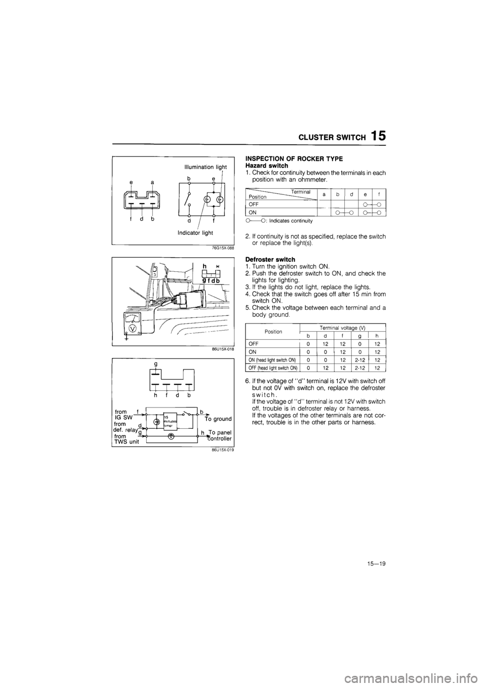
INSPECTION OF ROCKER TYPE
Hazard switch
1. Check for continuity between the terminals in each
position with an ohmmeter.
——____Terminal Position
^
a
b d
e
f
OFF
ON
-o
O
O:
Indicates continuity
2. If continuity is not as specified, replace the switch
or replace the light(s).
Defroster switch
1. Turn the ignition switch ON.
2. Push the defroster switch to ON, and check the
lights for lighting.
3. If the lights do not light, replace the lights.
4. Check that the switch goes off after 15 min from
switch ON.
5. Check the voltage between each terminal and a
body ground.
Position Terminal voltage
(V)
Position
b d f g h
OFF 0 12 12 0 12
ON 0 0 12 0 12
ON
(head light switch
ON) 0 0 12 2-12 12
OFF (head light switch
ON) 0 12 12 2-12 12
6. If the voltage of "d" terminal is 12V with switch off
but not OV with switch on, replace the defroster
switch.
If the voltage of "d" terminal is not 12V with switch
off, trouble is in defroster relay or harness.
If the voltages of the other terminals are not cor-
rect, trouble is in the other parts or harness.
86U15X-019
15—19
Page 1677 of 1865
15 METER
METER
STRUCTURAL VIEW
DIGITAL ELECTRONIC DISPLAY METER
ANALOG DISPLAY METER
76G15X-007
1. Speedometer 5. Warning and indicator lights
2. Tachometer 6. Tripmeter
3. Water temperature gauge 7. Twin tripmeter change switch
4. Fuel gauge 8. Fuel garge scale change switch
15—22
Page 1692 of 1865
WARNING LIGHT AND SENDER 1 5
76G15X-090
Seat Belt Warning Light
76G15X-043
EC-AT Mode Indicator Light
POWER and ECONO indicator lights
do
not
il-
luminate.
NG
Check the hold switch. Refer
to
page 7B—63
NG
Replace the switch.
OK
NG
Check the mode switch. Refer
to
page 7B—63
NG
Replace the switch.
fOK
Replace the bulb
or
repair the harness (Meter
to
mode switch, EC-AT switch
to
control unit).
76G15X-091
76G15X-044
15—37
Page 1693 of 1865
1 5 WARNING AND SENDER
Shift Indicator Light
All shift indicator lights do not Illuminate when ignition switch on. (other warning light are all right.)
Check the voltage
at BY
terminal
of
the inhibitor switch connector with ignition switch
on.
Terminal Voltage
BY 12V
NG
Repair the harness (Fuse box
to
inhibitor switch).
OK
Check the inhibitor switch. Refer
to
page 7B—65
NG
Replace the inhibitor switch. Check the inhibitor switch. Refer
to
page 7B—65 Replace the inhibitor switch.
OK
NG
Check the bulbs
of
the shift indicator lights.
NG
Replace the bulb.
OK
Turn the ignition switch on, and check the voltage
at
each terminal
of
the meter connector with each con-dition.
Terminal Selector lever Voltage
YL (2J) P 12V
RG (1L) R 12V
YR (2L) N 12V
Y(1V) D 12V
YB (1S) 2 12V
YW (1M) 1 12V
NG
Repair the harness (Inhibitor switch
to
meter).
76G15X-087
O/D OFF Indicator Light
OK
Repair the harness (O/D OFF switch
to
ground).
76G15X092
15-38
Page 1698 of 1865

CENTRAL PROCESSING UNIT (CPU) 1 5
REMOVAL AND INSTALLATION
1. Disconnect the negative battery cable.
2. Disconnect the CPU connectors.
3. Release the lock and remove the CPU from the
joint box.
4. Install in the reverse order of removal.
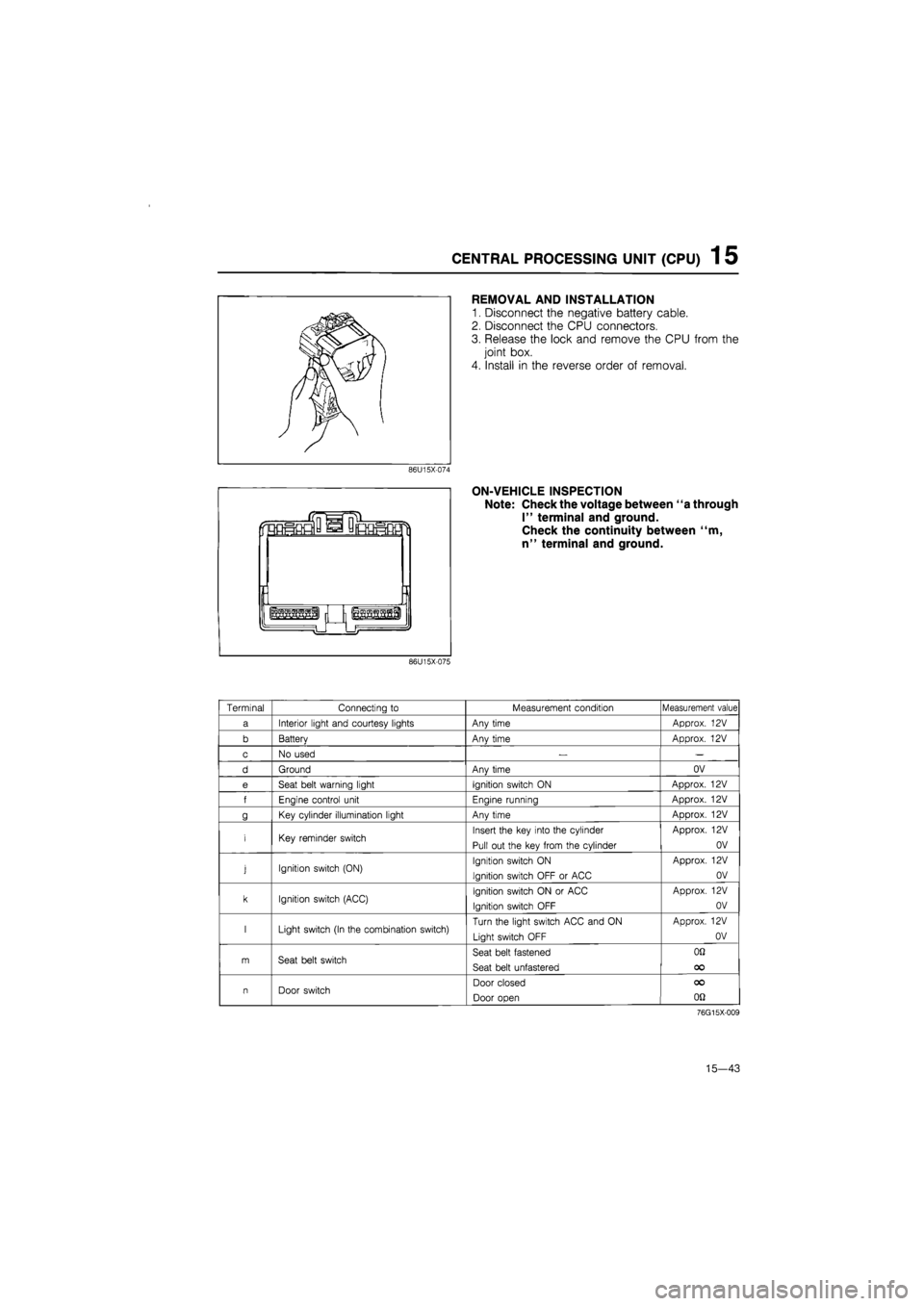
ON-VEHICLE INSPECTION
Note: Check the voltage between "a through
I" terminal and ground.
Check the continuity between "m,
n" terminal and ground.
86U15X-075
Terminal Connecting
to
Measurement condition Measurement value
a Interior light and courtesy lights Any time Approx.
12V
b Batterv Anv time Approx.
12V
c No used
— —
d Ground Anv time OV
e Seat belt warning light Ignition switch
ON
Approx.
12V
f Enaine control unit Enaine runnina Approx.
12V
g Key cylinder illumination light Any time Approx.
12V
i Key reminder switch Insert the key into the cylinder
Pull out the key from the cylinder
Approx.
12V
OV
j Ignition switch (ON) Ignition switch
ON
Ignition switch OFF
or
ACC
Approx.
12V
OV
k Ignition switch (ACC) Ignition switch
ON or
ACC
Ignition switch OFF
Approx.
12V
OV
I Light switch (In the combination switch) Turn the light switch ACC and
ON
Light switch OFF
Approx.
12V
OV
m Seat belt switch Seat belt fastened
Seat belt unfastered
OQ
OO
n Door switch Door closed
Door open
OO
on
76G15X-009
15—43
Page 1701 of 1865

1 5 TURN AND HAZARD LIGHT
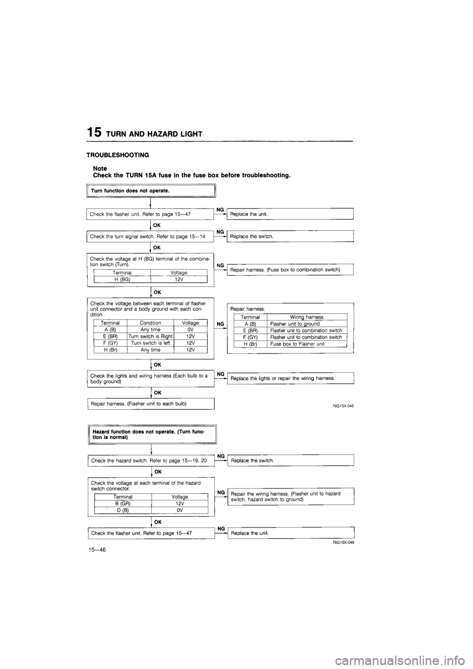
TROUBLESHOOTING
Note
Check the TURN 15A fuse in the fuse box before troubleshooting.
Terminal Voltage
H (BG) 12V
OK
Check the voltage between each terminal
of
flasher unit connector and
a
body ground with each con-dition.
Terminal Condition Voltage
A(B) Any time OV
E (BR) Turn switch
is
Riaht 12V
F (GY) Turn switch
is
left 12V
H (Br) Anv time 12V
OK
Turn function does not operate.
Check the flasher unit. Refer
to
page 15—47
OK
Check the turn signal switch. Refer
to
page 15—14
OK
NG
NG
Check the voltage
at H
(BG) terminal
of
the combina-tion switch (Turn).
Replace the unit.
Replace the switch.
NG
Repair harness. (Fuse box
to
combination switch)
Repair harness.
NG
Terminal Wiring harness
A (B) Flasher unit
to
ground
E (BR) Flasher unit
to
combination switch
F (GY) Flasher unit
to
combination switch
H (Bri Fuse box
to
Flasher unit
Check the lights and wiring harness (Each bulb
to a
body ground)
NG
Replace the lights
or
repair the wiring harness.
OK
Repair harness. (Flasher unit
to
each bulb)
76G15X-045
Hazard function does not operate. (Turn func-tion is normal)
Check the hazard switch. Refer
to
page 15—19,
20
OK
NG
Replace the switch.
Check the voltage
at
each terminal
of
the hazard
switch connector.
Terminal Voltage
B (GR) 12V
D (B) OV
15-46
NG
Repair the wiring harness. (Flasher unit
to
hazard
switch, hazard switch
to
ground)
OK
Check the flasher unit. Refer
to
page 15—47
NG
Replace the unit.
76G15X-046