1987 MAZDA 626 lights
[x] Cancel search: lightsPage 1702 of 1865
TURN AND HAZARD LIGHT 1 5
Rapid flashing
Check the lights and wiring harness between each
bulb and
a
body ground (rapid flashing side).
86U15X-081
76G15X-047
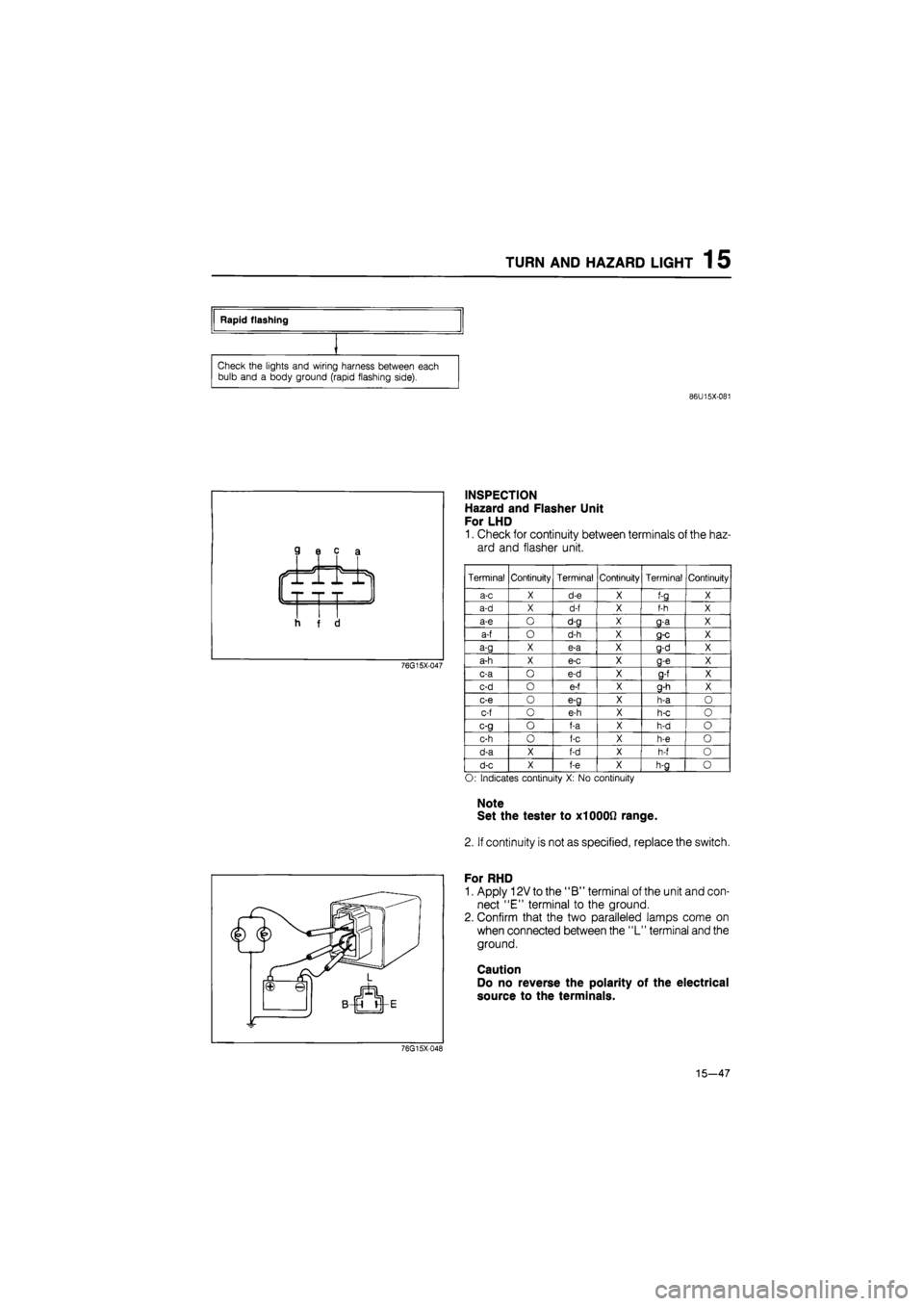
INSPECTION
Hazard and Flasher Unit
For LHD
1. Check for continuity between terminals of the haz-
ard and flasher unit.
Terminal Continuity Terminal Continuity Terminal Continuity
a-c X d-e X f-g X
a-d X d-f X f-h X
a-e O d-g X g-a X
a-f O d-h X g-c X
a-g X e-a X g-d X
a-h X e-c X g-e X
c-a
o
e-d X 9-f X
c-d
o
e-f X g-h X
c-e
o
e-g X h-a
O
c-f
o
e-h X h-c
o
c-g
o
f-a X h-d
o
c-h
o
f-c X h-e
o
d-a X f-d X h-f
o
d-c X f-e X h-g
o
O: Indicates continuity
X: No
continuity
Note
Set the tester to X1000Q range.
2. If continuity is not as specified, replace the switch.
For RHD
1. Apply 12V to the "B" terminal of the unit and con-
nect "E" terminal to the ground.
2. Confirm that the two paralleled lamps come on
when connected between the "L" terminal and the
ground.
Caution
Do no reverse the polarity of the electrical
source to the terminals.
76G15X048
15—47
Page 1705 of 1865
1 5 STOP LIGHT
Both side stop lights do not illuminate when brake on.
Check the voltage
at A
(GW) terminal
of
stop light switch connector.
NG
Terminal Voltage
A (GW) 12V
Repair harness. (Fuse box
to
stop light switch)
OK
Check the stop light switch. Refer
to
page 15—51
NG
Replace the switch.
OK
Check the voltage between each terminal
of
the stop and tail light checker connector and
a
body ground when brake
on.
Terminal Voltage
B(B) OV
C (WG) 12V
NG Repair the wiring harness. (Stop light switch
to
stop and tail light checker, stop and tail light checker
to
body ground)
OK
OK
Repair the wiring harness. (Stop and tail light checker to bulb, bulb
to
body ground)
76G15X-049
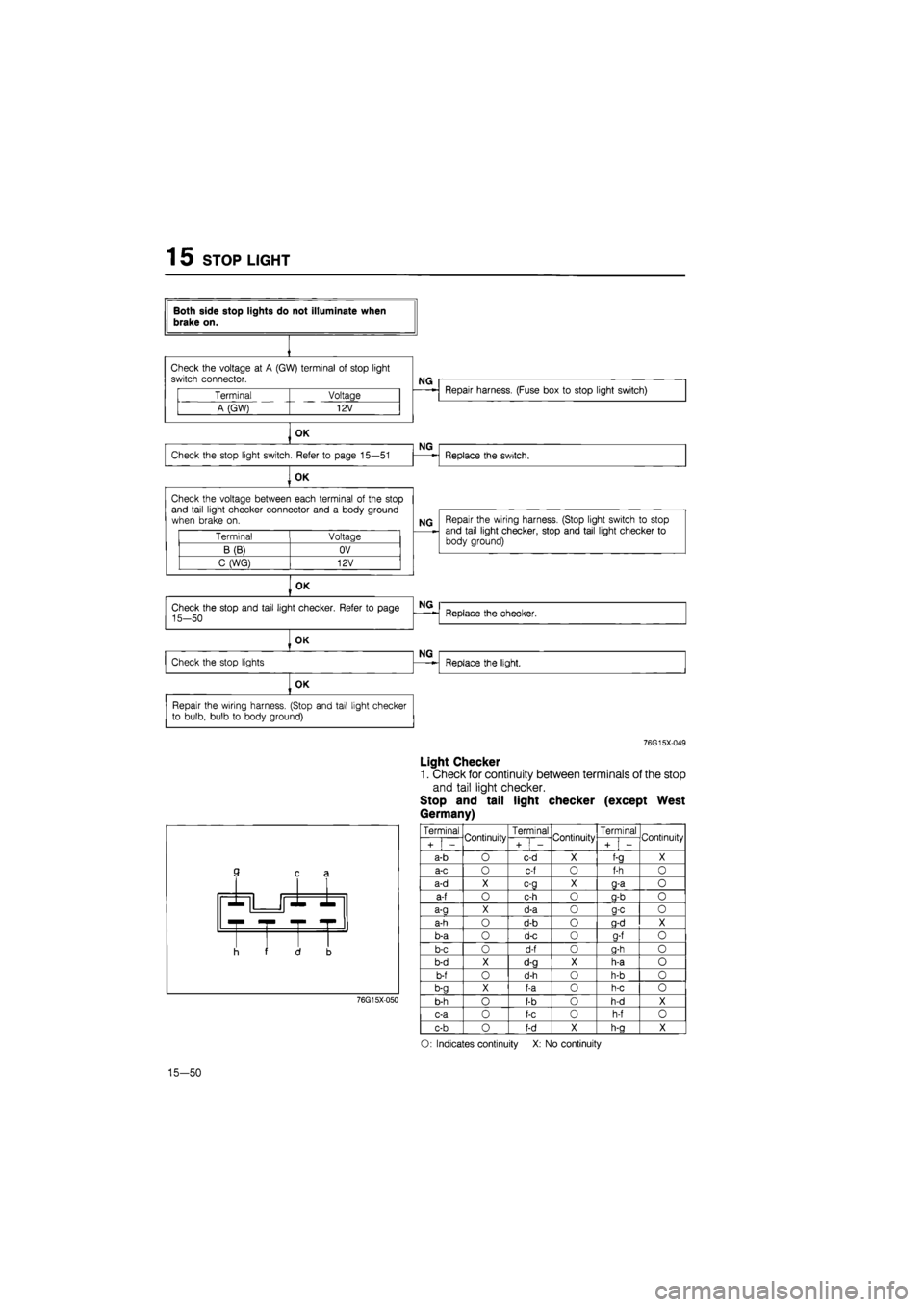
Light Checker
1. Check for continuity between terminals of the stop
and tail light checker.
Stop and tail light checker (except West
Germany)
3 c £
r -r •
I i f 1 3
76G15X050
Terminal Continuity Terminal Continuity Terminal Continuity
i + i -
Continuity
+
1
-
Continuity
i + i -
Continuity
a-b
O
c-d
X
f-a
X
a-c
O
c-f
o
f-h
0
a-d
X c-g X g-a o
a-f
o
c-h
o
g-b
o
a-a
X
d-a
o a-c o
a-h
o
d-b
o
g-d
X
b-a
o
d-c
0
a-f
o
b-c
o
d-f
o
g-h
o
b-d
X
d-g
X
h-a
o
b-f
o
d-h
o
h-b
o
b-g
X
f-a
0
h-c
o
b-h
o
f-b
o
h-d
X
c-a
0
f-c
o
h-f
o
c-b
o
f-d
X
h-a
X
O: Indicates continuity
X: No
continuity
15-50
Page 1706 of 1865
STOP
LIGHTS
1
5
Stop light checker
9 c a
d b
Tail light checker
c a
J f d b
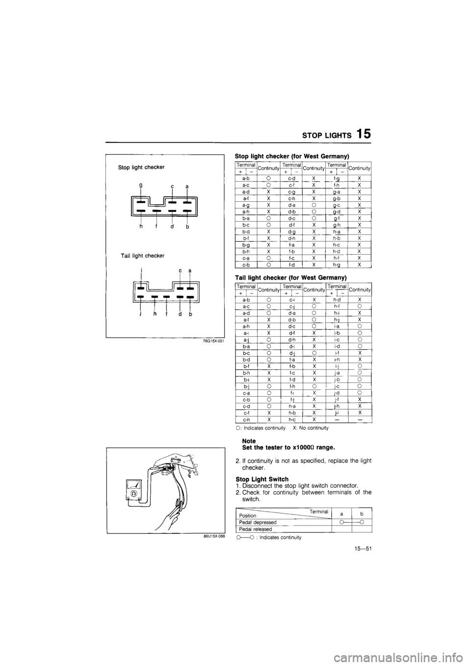
Stop light checker (for West Germany)
76G15X-051
Terminal Continuity Terminal Continuity Terminal Continuity
+ -
Continuity
+ -
Continuity
+ -
Continuity
a-b O c-d X
X f:3__ X
a-c 0 c-f
X
X f-h X
a-d X c-g X g-a X
a-f X c-h X g-b X
a-g X d-a O
a-c
X
a-h X d-b
o
g-d X
b-a
o
d-c
o g-f
X
b-c
o
d-f X g-h X
b-d X d-g X h-a X
b-f X d-h X h-b X
b-g X f-a X h-c X
b-h X f-b X h-d X
c-a
0
f-c X h-f X
c-b
0
f-d X h-g X
Tail light checker (for West Germany)
Terminal Continuity Terminal Continuity Terminal Continuity
+ -
Continuity
+ i -
Continuity
+ -
Continuity
a-b
O
c-i X h-d X
a-c
0
oj
O
h-f
O
a-d
o
d-a
o
h-i X
a-t X d-b
o
h-j X
a-h X d-c
o i-a o
a-i X d-f X
i-b o
a-j
o
d-h X
i-c o
b-a
o
d-i X
i-d o
b-c
o
d-j
o
i-f X
b-d
o
f-a X i-h X
b-f X f-b X
i-j o
b-h X f-c X
j-a o
b-i X f-d X
j-b o
b-j
o
f-h
o j-c o
c-a
o
f-i X J-d
o
c-b
o
f-j X J-f X
c-d
o
h-a X i-h X
c-f X h-b X j-i X
c-h X h-c X
—
O: Indicates continuity
X: No
continuity
Note
Set the tester to x1000ft range.
2. If continuity is not as specified, replace the light
checker.
Stop Light Switch
1. Disconnect the stop light switch connector.
2. Check for continuity between terminals of the
switch.
———Terminal Position
~
•———____ a b
Pedal deoressed
Pedal released
86U15X-088
O
O :
Indicates continuity
15—51
Page 1739 of 1865
1 5 CRUISE CONTROL SYSTEM
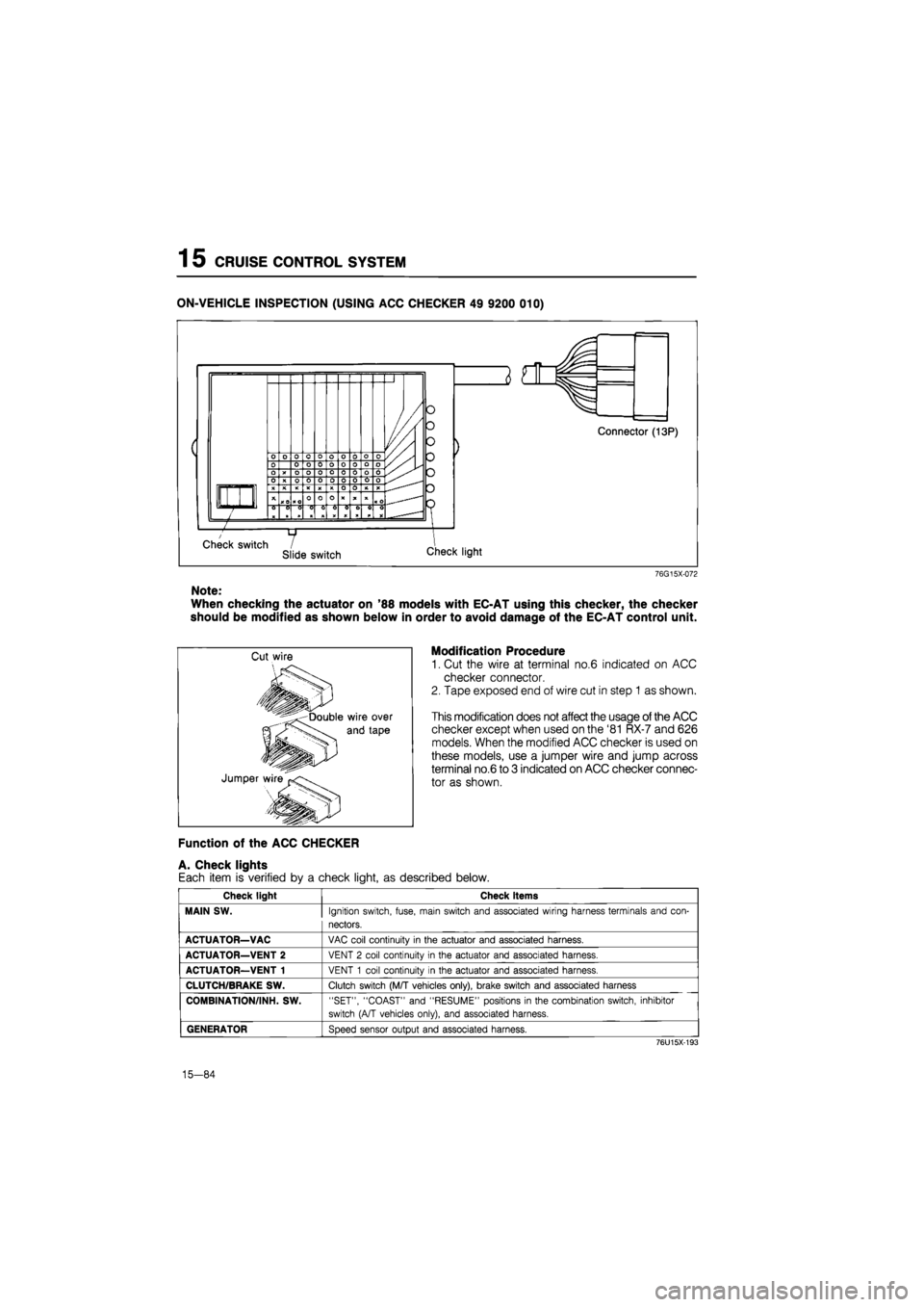
ON-VEHICLE INSPECTION (USING ACC CHECKER 49 9200 010)
76G15X-072
Note:
When checking the actuator on '88 models with EC-AT using this checker, the checker
should be modified as shown below in order to avoid damage of the EC-AT control unit.
Modification Procedure
1. Cut the wire at terminal no.6 indicated on ACC
checker connector.
2. Tape exposed end of wire cut in step 1 as shown.
This modification does not affect the usage of the ACC
checker except when used on the '81 RX-7 and 626
models. When the modified ACC checker is used on
these models, use a jumper wire and jump across
terminal no.6 to 3 indicated on ACC checker connec-
tor as shown.
Function of the ACC CHECKER
A. Check lights
Each item is verified by a check light, as described below.
Check light Check items
MAIN SW.
Ignition switch, fuse, main switch and associated wiring harness terminals and con-
nectors.
ACTUATOR—VAC
VAC coil continuity
in
the actuator and associated harness.
ACTUATOR—VENT 2
VENT
2
coil continuity
in
the actuator and associated harness.
ACTUATOR—VENT 1
VENT
1
coil continuity
in
the actuator and associated harness.
CLUTCH/BRAKE SW.
Clutch switch (M/T vehicles only), brake switch and associated harness
COMBINATION/INH. SW.
"SET", "COAST" and "RESUME" positions
in
the combination switch, inhibitor
switch (A/T vehicles only), and associated harness.
GENERATOR
Speed sensor output and associated harness.
76U15X-193
15-84
Page 1741 of 1865
1
5
CRUISE CONTROL SYSTEM
Checking
the
System
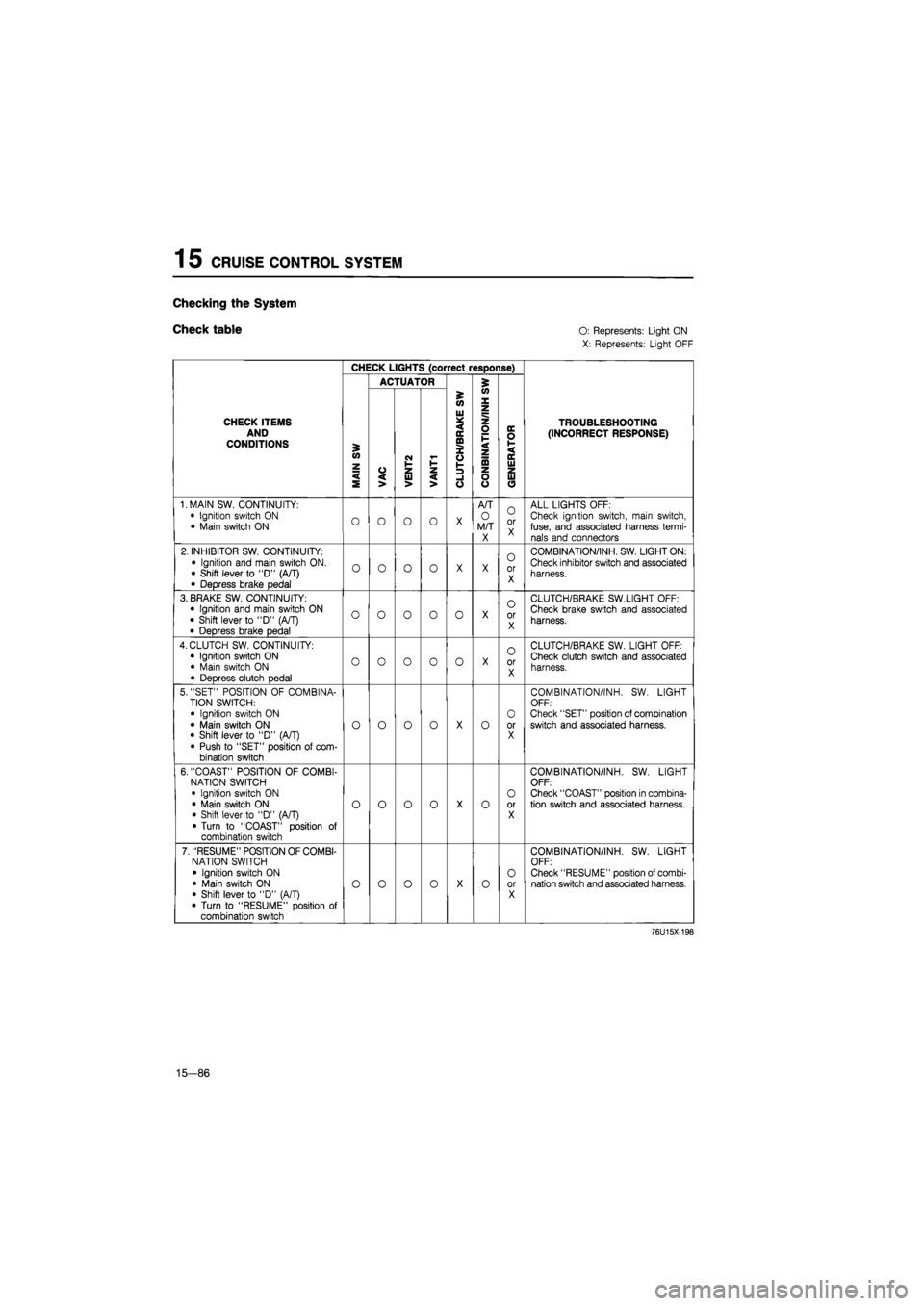
Check table O:
Represents: Light ON
X: Represents: Light OFF
CHECK LIGHTS (correct response)
ACTUATOR 5
CHECK ITEMS AND CONDITIONS
MAIN
SW
VAC
i
VENT2 VANT1
i
'
CLUTCH/BRAKE
SW
CONBINATION/INH
S
'
GENERATOR
TROUBLESHOOTING (INCORRECT RESPONSE)
1. MAIN SW. CONTINUITY:
• Ignition switch
ON
• Main switch
ON O O O o
X
A/T
O
M/T X
O
or X
ALL LIGHTS OFF: Check ignition switch, main switch, fuse, and associated harness termi-nals and connectors
2. INHIBITOR SW. CONTINUITY:
• Ignition and main switch ON. • Shift lever
to "D"
(A/T)
• Depress brake pedal
o o o o
X X
0
or X
COMBINATION/INH. SW. LIGHT ON:
Check inhibitor switch and associated
harness.
3. BRAKE SW. CONTINUITY: • Ignition and main switch
ON
• Shift lever
to
"D"
(A/T)
• Depress brake pedal
o o o o 0
X
o
or X
CLUTCH/BRAKE SW.LIGHT OFF:
Check brake switch and associated
harness.
4. CLUTCH SW. CONTINUITY:
• Ignition switch
ON
• Main switch
ON
• Depress clutch pedal
o o o 0 o
X
O
or X
CLUTCH/BRAKE SW. LIGHT OFF: Check clutch switch and associated harness.
5. "SET" POSITION
OF
COMBINA-TION SWITCH:
• Ignition switch
ON
• Main switch
ON
• Shift lever
to "D"
(A/T) • Push
to
"SET" position
of
com-bination switch
o o o o
X
o
O
or X
COMBINATION/INH.
SW.
LIGHT OFF: Check "SET" position of combination switch and associated harness.
6. "COAST" POSITION
OF
COMBI-NATION SWITCH • Ignition switch
ON
• Main switch
ON
• Shift lever
to "D"
(A/T) • Turn
to
"COAST" position
of
combination switch
o o o o
X
o
O
or X
COMBINATION/INH.
SW.
LIGHT OFF: Check "COAST" position in combina-tion switch and associated harness.
7. "RESUME" POSITION OF COMBI-NATION SWITCH
• Ignition switch
ON
• Main switch
ON
• Shift lever
to "D"
(A/T)
• Turn
to
"RESUME" position
of
combination switch
o o o o
X
o O
or X
COMBINATION/INH.
SW.
LIGHT OFF: Check "RESUME" position of combi-nation switch and associated harness.
76U15X-198
15—86
Page 1742 of 1865
CRUISE CONTROL SYSTEM 1 5
CHECK LIGHTS (correct response)
ACTUATOR £
5 (O
W X
CHECK ITEMS AND CONDITIONS £ <0 z
VAC
CM I-1-z
Ul * < IE ffl X o V-
z o F < z ta
DC O 1-< DC Ui
TROUBLESHOOTING
(INCORRECT RESPONSE)
< S VAC UJ > < > -1 o o o UJ O
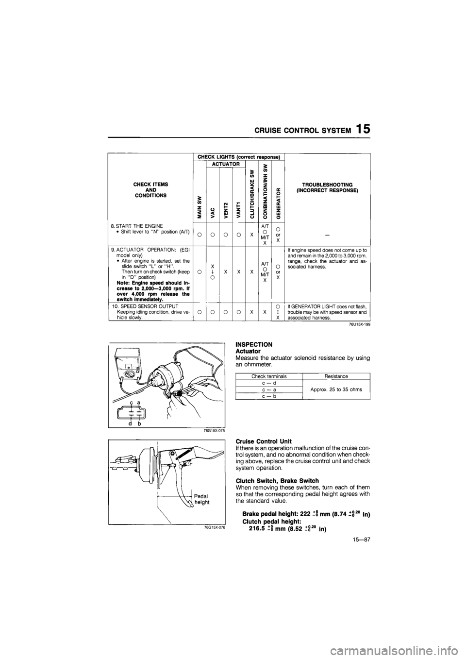
8. START THE ENGINE
• Shift lever to "N" position (A/T) O O O o X
A/T
O M/T X
O or X —
9. ACTUATOR OPERATION: (EGI model only) • After engine is started, set the slide switch "L" or "H". Then turn on check switch (keep in "D" position) Note: Engine speed should in-crease to 2,000—3,000 rpm. If over 4,000 rpm release the switch immediately.
o
X
1
o
X X X
A/T O M/T X
O or X
If engine speed does not come up to and remain
in
the
2,000
to
3,000
rpm. range, check the actuator and as-sociated harness.
10. SPEED SENSOR OUTPUT
Keeping idling condition, drive ve-
hicle slowly. o o 0 o X X 0 1 X
If GENERATOR LIGHT does not flash, trouble may be with speed sensor and associated harness.
76U15X-199
INSPECTION
Actuator
Measure the actuator solenoid resistance by using
an ohmmeter.
Check terminals Resistance
c-d
Approx. 25 to 35 ohms c — a Approx. 25 to 35 ohms
c — b
Approx. 25 to 35 ohms
76G15X-075
Cruise Control Unit
If there is an operation malfunction of the cruise con-
trol system, and no abnormal condition when check-
ing above, replace the cruise control unit and check
system operation.
Clutch Switch, Brake Switch
When removing these switches, turn each of them
so that the corresponding pedal height agrees with
the standard value.
76G15X-076
Brake pedal height: 222 ±1 mm (8.74 1820
Clutch pedal height:
216.5 ±8 mm (8.52 ±820 In)
in)
15-87
Page 1853 of 1865
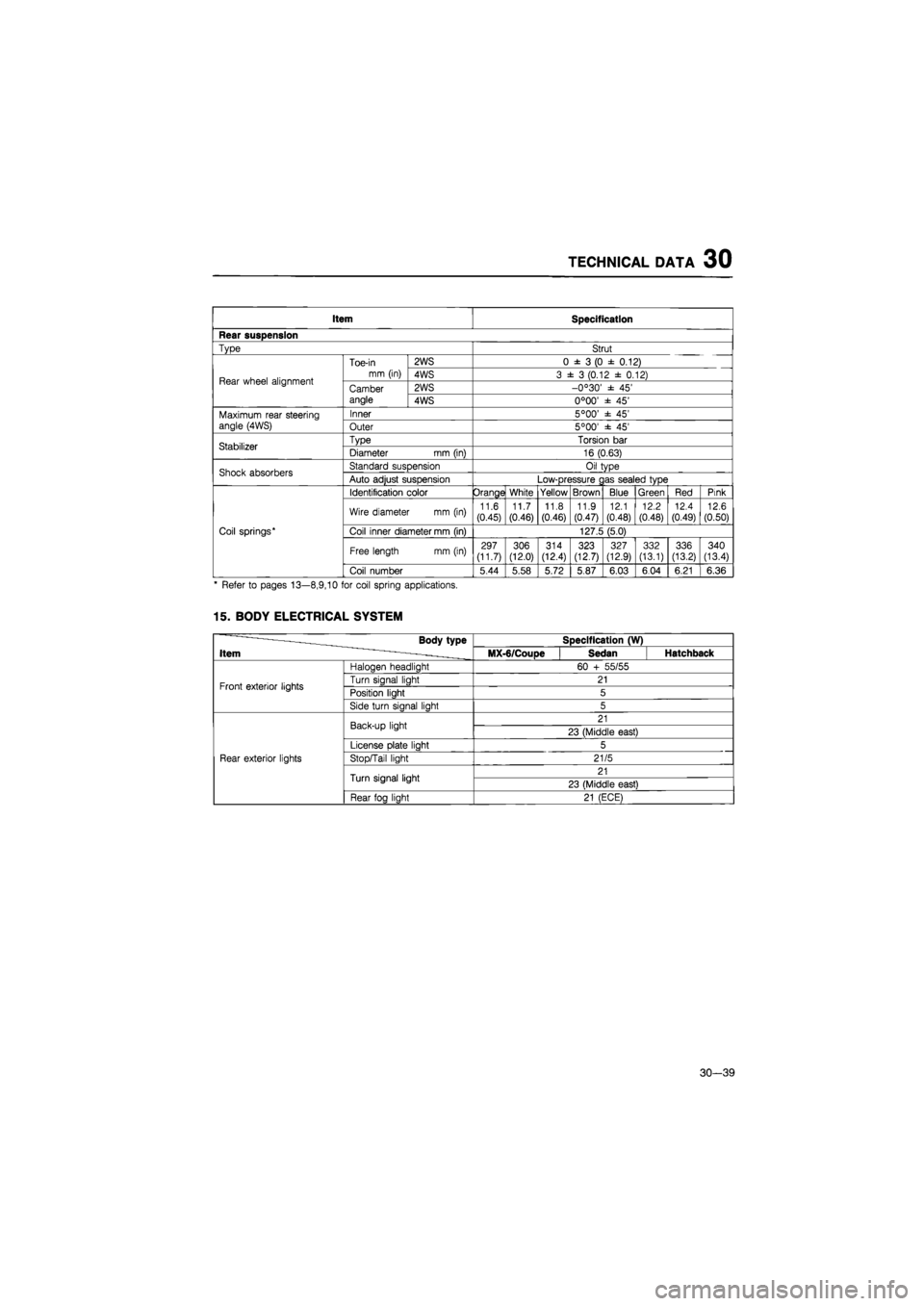
TECHNICAL DATA 30
Item Specification
Rear suspension
Type Strut
Rear wheel alignment
Toe-in
mm (in)
2WS 0
± 3 (0 ±
0.12)
Rear wheel alignment
Toe-in
mm (in) 4WS 3
± 3
(0.12
±
0.12) Rear wheel alignment Camber angle
2WS -0°30'
± 45'
Rear wheel alignment Camber angle 4WS 0°00'
± 45'
Maximum rear steering angle (4WS)
Inner 5°00'
± 45'
Maximum rear steering angle (4WS) Outer 5°00'
± 45'
Stabilizer Type Torsion
bar
Stabilizer Diameter
mm
(in) 16 (0.63)
Shock absorbers Standard suspension Oil type Shock absorbers Auto adjust suspension Low-pressure
c
as sealed type
Coil springs*
Identification color Orange White Yellow Brown Blue Green Red Pink
Coil springs*
Wire diameter
mm (in)
11.6 (0.45)
11.7
(0.46)
11.8
(0.46) 11.9
(0.47)
12.1
(0.48)
12.2
(0.48)
12.4
(0.49)
12.6
(0.50)
Coil springs* Coil inner diameter mm (in) 127.5 (5.0) Coil springs*
Free length mm (in) 297 (11.7) 306 (12.0)
314
(12.4) 323 (12.7)
327 (12.9) 332
(13.1)
336
(13.2)
340
(13.4)
Coil springs*
Coil number 5.44 5.58 5.72 5.87 6.03 6.04 6.21 6.36
* Refer
to
pages 13—8,9,10
for
coil spring applications.
15. BODY ELECTRICAL SYSTEM
-—— Body type
Item ~ - -.
Specification (W) -—— Body type
Item ~ - -. MX-6/CouDe Sedan Hatchback
Front exterior lights
Haloaen headliaht 60
+
55/55
Front exterior lights Turn sianal liaht 21 Front exterior lights Position light 5 Front exterior lights
Side turn sianal liaht 5
Rear exterior lights
Back-up light 21
Rear exterior lights
Back-up light 23 (Middle east)
Rear exterior lights
License
Dlate
liaht 5
Rear exterior lights Stop/Tail light 21/5 Rear exterior lights
Turn signal light 21
Rear exterior lights
Turn signal light 23 (Middle east)
Rear exterior lights
Rear foa liaht 21 (ECE)
30—39
Page 1854 of 1865
30 TECHNICAL DATA
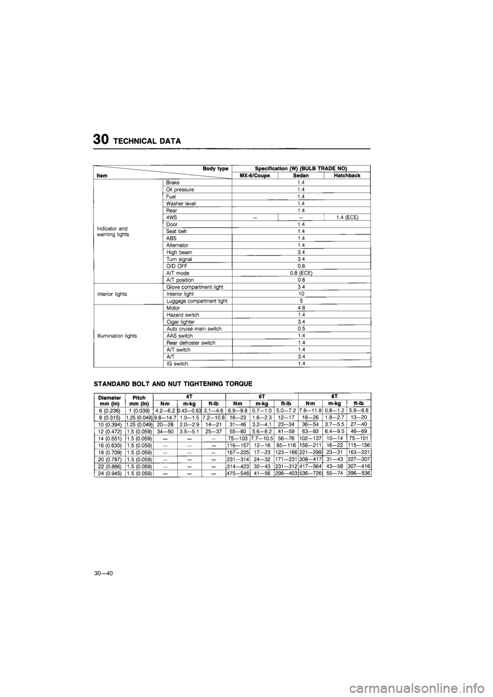
Body type Specification (W) (BULB TRADE NO)
Item MX-6/Coupe Sedan Hatchback
Brake 1.4
Oil pressure 1.4
Fuel 1.4
Washer level 1.4
Rear 1.4
4WS
— —
1.4 (ECE)
Indicator and warning lights
Door 1.4 Indicator and warning lights Seat belt 1.4 Indicator and warning lights ABS 1.4
Alternator 1.4
High beam 3.4
Turn signal 3.4
O/D OFF 0.8
A/T mode 0.8 (ECE)
A/T position 0.8
Glove compartment light 3.4
Interior lights Interior light 10
Luggage compartment light 5
Motor 4.8
Hazard switch 1.4
Cigar lighter 3.4
Auto cruise main switch 0.5
Illumination lights AAS switch 1.4
Rear defroster switch 1.4
A/T switch 1.4
A/T 3.4
IG switch 1.4
STANDARD BOLT AND NUT TIGHTENING TORQUE
Diameter
mm (in)
Pitch
mm (in)
4T 6T 8T Diameter
mm (in)
Pitch
mm (in) N-m m-kg ft-lb N-m m-kg ft-lb N-m m-kg ft-lb
6 (0.236) 1 (0.039) 4.2-6.2 0.43-0.63 3.1-4.6 6.9-9.8 0.7-1.0 5.0-7.2 7.8-11.8 0.8-1.2 5.8—8.8
8 (0.315) 1.25 (0.049) 9.8—14.7 1.0-1.5 7.2-10.8 16-23 1.6-2.3 12-17 18—26 1.8-2.7 13-20
10 (0.394) 1.25 (0.049) 20-28 2.0—2.9 14-21 31-46 3.2-4.1 23—34 36-54 3.7-5.5 27-40
12 (0.472) 1.5 (0.059) 34—50 3.5-5.1 25-37 55-80 5,6-8.2 41-59 63-93 6.4-9.5 46-69
14 (0.551) 1.5 (0.059)
— — —
75-103 7.7-10.5 56-76 102—137 10-14 75-101
16 (0.630) 1.5 (0.059)
— — —
116-157 12-16 85-116 156-211 16-22 115-156
18 (0.709) 1.5 (0.059)
— — —
167-225 17-23 123-166 221-299 23-31 163—221
20 (0.787) 1.5 (0.059)
— — —
231-314 24-32 171-231 308—417 31-43 227-307
22 (0.866) 1.5 (0.059)
— — —
314—423 32-43 231-312 417—564 43-58 307-416
24 (0.945) 1.5 (0.059)
— — —
475—546 41—56 298—403 536-726 55-74 396-536
30—40