Page 1379 of 1865
ELECTRICAL COMPONENTS
OF
ELECTRONICALLY-CONTROLLED POWER STEERING (ECPS) 1 0
Flow Chart
P/S—1
Failure of solenoid valve or wiring harness (Control unit to Solenoid valve)
Disconnect control unit connector. Check resistance between terminals.
Check voltage between (YL) and D (B) terminal of
control unit connector with engine running
OK
Terminal Resistance
M(LB)—N(LG) 3.5 — 7Q
Check control unit connector, solenoid valve connec-tor, and joint connector for connection, and check output pattern again.
NG
Check the solenoid valve (Refer to page 10—93),
NG
Replace solenoid valve.
P/S-Z Broken wiring harness
(Control unit to Coil)
Terminate of control unit connector with engine running.
NG
Replace control unit.
OK Repair wiring harness (Control unit to Solenoid valve).
Terminal Voltage
L(YL)-D(B) Approx. 12V
NG Repair the wiring harness (Control unit to Ignition
coil).
OK
Replace control unit.
76G10X-025
10—91
Page 1391 of 1865

ELECTRICAL COMPONENTS OF 4-WHEEL STEERING 1 0
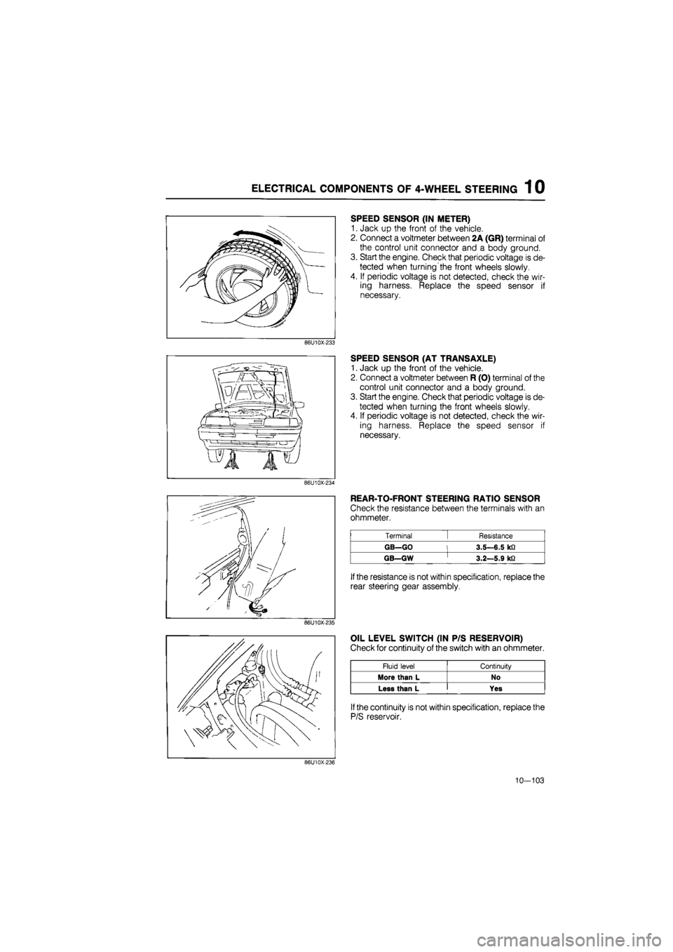
SPEED SENSOR (IN METER)
1. Jack up the front of the vehicle.
2. Connect a voltmeter between 2A (GR) terminal of
the control unit connector and a body ground.
3. Start the engine. Check that periodic voltage is de-
tected when turning'the front wheels slowly.
4. If periodic voltage is not detected, check the wir-
ing harness. Replace the speed sensor if
necessary.
86U10X-233
SPEED SENSOR (AT TRANSAXLE)
1. Jack up the front of the vehicle.
2. Connect a voltmeter between R (O) terminal of the
control unit connector and a body ground.
3. Start the engine. Check that periodic voltage is de-
tected when turning the front wheels slowly.
4. If periodic voltage is not detected, check the wir-
ing harness. Replace the speed sensor if
necessary.
86U10X-234
REAR-TO-FRONT STEERING RATIO SENSOR
Check the resistance between the terminals with an
ohmmeter.
Terminal [ Resistance
GB—GO l 3.5—6.5 kfi
GB—GW ' 3.2—5.9 kfi
If
the resistance is not within specification, replace the
rear steering gear assembly.
86U10X-235
OIL LEVEL SWITCH (IN P/S RESERVOIR)
Check for continuity of the switch with an ohmmeter.
Fluid level Continuity
More than L No
Less than L Yes
If
the continuity is not within specification, replace the
P/S reservoir.
86U10X-236
10—103
Page 1397 of 1865

TROUBLESHOOTING GUIDE 1 1
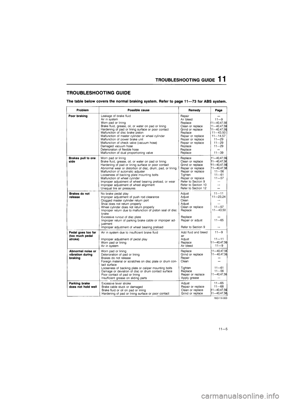
TROUBLESHOOTING GUIDE
The table below covers the normal braking system. Refer to page 11—73 for ABS system.
Problem Possible cause Remedy Page
Poor braking Leakage of brake fluid Air in system Worn pad or lining
Brake fluid, grease, oil, or water on pad or lining Hardening of pad or lining surface or poor contact Malfunction of disc brake piston Malfunction of master cylinder or wheel cylinder Malfunction of power brake unit
Malfunction of check valve (vacuum hose)
Damaged vacuum hose Deterioration of flexible hose Malfunction of dual proportioning valve
Repair Air bleed Replace
Clean or replace Grind or replace Replace Repair or replace Repair or replace Repair or replace Replace Replace Replace
11-9 11-40,47,56 11-40,47,56 11-40,47,56 11—43,50 11-14,57 11-29 11-29 11-29
11-39
Brakes pull to one
side
Worn pad or lining
Brake fluid, grease, oil, or water on pad or lining Hardening of pad or lining surface or poor contact Abnormal wear or distortion of disc, drum, pad, or lining Malfunction of automatic adjuster Looseness of backing plate mounting bolts Malfunction of wheel cylinder
Improper adjustment of wheel bearing preload, or wear Improper adjustment of wheel alignment Unequal tire air pressures
Replace Clean or replace Grind or replace Repair or replace Repair or replace Tighten
Repair or replace Refer to Section 9 Refer to Section 10 Refer to Section 12
11-40,47,56 11-40,47,56 11-40,47,56 11-40,47,56 11-56 11-61 11-57
Brakes do not
release
No brake pedal play
Improper adjustment of push rod clearance
Clogged master cylinder return port Shoe does not return properly Wheel cylinder does not return properly Improper return due to malfunction of piston seal of disc brake Excessive runout of disc plate Improper return of parking brake cable or improper ad-justment
Improper adjustment of wheel bearing preload
Adjust
Adjust
Clean
Adjust Clean or replace Replace
Replace Repair or adjust
Refer to Section 9
11-11
11—23,24
11-57 11—43,50
11-65
Pedal goes too far (too much pedal stroke)
Air in system due to insufficient brake fluid
Improper adjustment of pedal play Worn pad or lining Air in system
Add fluid and bleed air
Adjust Replace Air bleed
11—9
11—11 11-40,47,56 11-9
Abnormal noise or
vibration during
braking
Worn pad or lining Deterioration of pad or lining Brakes do not release
Foreign material or scratches on disc plate or drum con-tact surface
Looseness of backing plate or caliper mounting bolts Damage or deviation of disc or drum contact surface Poor contact of pad or lining Insufficient grease on sliding parts
Replace
Grind or replace
Repair
Clean
Tighten Replace Repair or replace Apply grease
11-40,47,56 11-40,47,56
11-61 11-56 11-40,47,56
Parking brake
does not hold well
Excessive lever stroke
Brake cable stuck or damaged
Brake fluid or oil on pad or lining Hardening of pad or lining surface or poor contact
Adjust
Repair or replace Clean or replace Grind or replace
11-65
11-68
11-40,47,56
11-40,47,56
76G11X-003
11—5
Page 1427 of 1865
VACUUM PUMP 1 1
VACUUM PUMP
1. Disconnect the vacuum hose and release the re-
maining vacuum.
2. Connect a vacuum gauge as shown in the figure.
3. Run the engine at idle speed.
Idle speed: 720 1 20 rpm
4. Check that the vacuum reaches 500 mmHg (19.7
inHg) in 8 seconds or less.
5. Check that the maximum vacuum is within approx.
700—720 mmHg (27.6—28.3 inHg) in 80 sec-
onds or less.
REMOVAL AND INSTALLATION
1. Remove in the sequence shown in the figure.
2. Install in the reverse order of removal, referring to installation note for specially marked parts.
Note
The engine oil will leak out when disconnecting the oil hose. Prepare a suitable container
for it to drain into.
76G11X-038
76G11X-037
1. Vacuum hose
2. Oil return hose
3. Oil inlet hose
4. Drive velt cover
5. Vacuum pump
Page 1437 of 1865
FRONT DISC BRAKE 1 1
INSPECTION
Check the following and replace any faulty parts.
Disc Pad
1. Oil or grease on facing
2. Abnormal wear or cracks
3. Deterioration or heat damage 4. Remaining lining thickness
Thickness: 2.0 mm (0.08 in) min.
86U11X079
Disc Plate
1. Runout
Runout: 0.1 mm (0.004 in) max.
Caution
a) There must be no wheel bearing looseness.
b) Measure at the outer edge of the disc plate
surface.
86U11X-080
2. Wear or damage
Thickness specifications:
mm (in)
Standard Minimum
13 inch-wheel 20 (0.79) 18 (0.71)
14 or 15 inch-wheel 24 (0.94) 22 (0.86)
76G11X-046
11-45
Page 1446 of 1865
1 1 REAR DISC BRAKE
INSPECTION
Check the following and replace or repair any faulty
parts.
Disc Pad
1. Oil or grease on facing
2. Abnormal wear or cracks
3. Deterioration or heat damage
4. Remaining lining thickness
Thickness: 1 mm (0.04 in) min.
76G11X-086
Disc Plate
1. Runout
Runout: 0.1 mm (0.004 in) max.
Caution
a) There must be no wheel bearing looseness.
b) Measure at the outer edge of the disc plate
surface.
86U11X-104
2. Wear or damage
Thickness
Standard: 10 mm (0.39 in)
Minimum: 8 mm (0.31 in)
86U11X-105
11—54
Page 1513 of 1865
1 3 FRONT SHOCK ABSORBER AND SPRING
76G13X-015
I N
49 G034 102 1
| 49 G034 103 | iBHssfllil 49 G034 101 |
mmy
LojaiiaiciS]
86U13X-018
76G13X-016
Disassembly Note
1. Loosen the piston rod upper nut several turns, bu
do not remove.
Caution
a) Do not remove the nut.
b) Use copper or aluminum plates in the jawj
of a vice.
2. Set the SST in a vise.
3. Secure the shock absorber in the SST.
4. Compress the coil spring with the SST, then re
move the upper nut.
5. Remove the coil spring.
Inspection Note
Check the following and repair or replace any fault}
parts.
1. Oil leakage or abnormal noise from shock ab
sorbers
2. Deterioration or damage of mounting block anc
bearing
3. Wear or damage of bound stopper
4. Smooth rotation of control rod (AAS)
86U13X-020
13—16
Page 1514 of 1865
FRONT SHOCK ABSORBER AND SPRING 1 3
Assembly Note
1. Set the SST in a vise
2. Secure the shock absorber in the SST.
3. Install the bound stopper and dust boot to the
shock absorber.
4. Install the compressed coil spring (compressed
with SST).
5. Install the rubber seat, spring upper seat, bearing
and mounting block.
86U13X-021
6. Remove the SST.
7. Secure the mounting block in a vise.
Caution
Use copper or aluminum plates in the jaws of
a vice.
8. Tighten the piston rod upper nut.
Tightening torque:
64—84 Nm (6.5—8.2 m-kg, 47—59 ft-lb)
Caution
Check that the spring is well seated in the up-
per seats.
13—17