Page 1799 of 1865
16 COMPRESSOR
DISASSEMBLY OF COMPRESSOR
Shaft Seal Assembly
1. Using the SST, remove the shaft seal cover as fol-
lows: attach the remover hook to the shaft seal cov-
er hook and draw the cover out slowly.
76G16X-608
Compressor Oil
1. Remove the drain plug and the oil filler plug, then
drain out the oil.
2. Measure the drained oil with a measuring cylinder.
3. Check the drained oil for any of the following con-
ditions:
a) Whether the opacity of the oil has increased.
b) Whether the oil color has changed to red.
c) Whether foreign matter, such as metal filings,
etc., is present in the oil.
Note:
If the oil drained from the compressor is as
described above, replaced it with new oil.
69G16X-037
16—16
Page 1802 of 1865

COMPRESSOR 16
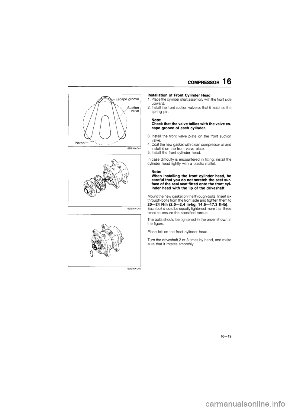
Escape groove
^ / / / / j / / ' / / / / /
' / / I / /
1 \ \ x Suction \ \ \/ valve
n W: \ / / y /
I u
Piston— ^
69G16X-044
69G16X-045
Installation of Front Cylinder Head
1. Place the cylinder shaft assembly with the front side
upward.
2. Install the front suction valve so that it matches the
spring pin.
Note:
Check that the valve tallies with the valve es-
cape groove of each cylinder.
3. Install the front valve plate on the front suction
valve.
4. Coat the new gasket with clean compressor oil and
install it on the front valve plate.
5. Install the front cylinder head.
In case difficulty is encountered in fitting, install the
cylinder head lightly with a plastic mallet.
Note:
When installing the front cylinder head, be
careful that you do not scratch the seat sur-
face of the seal seat fitted onto the front cyl-
inder head with the lip of the driveshaft.
Mount the new gasket on the through-bolts. Insert six
through-bolts from the front side and tighten them to
20—24 N m (2.0—2.4 m-kg, 14.5—17.3 ft-lb)
Each bolt should be equally tightened more than three
times to ensure the specified torque.
The bolts should be tightened in the order shown in
the figure.
Place felt on the front cylinder head.
Turn the driveshaft 2 or 3 times by hand, and make
sure that it rotates smoothly.
69G16X046
16—19
Page 1807 of 1865

16 CONDENSER
CONDENSER
ON-VEHICLE INSPECTION
1. Check the condenser fins for blockage or damage.
If the fins are clogged, clean them with compressed air.
If the fins are bent, straighten them with a screwdriver or pair of pliers.
2. Check the condenser fittings for leakage.
Repair or replace, if necessary.
REMOVAL OF CONDENSER
1. Discharge the air conditioning system. (Refer to page 16—9.)
2. Remove the front grille and the air seal cover.
3. Disconnect the discharge flexible hose from the condenser inlet fitting.
4. Disconnect the liquid line pipe from the condenser outlet fitting.
Note:
Plug the open fittings immediately to keep moisture out of the system.
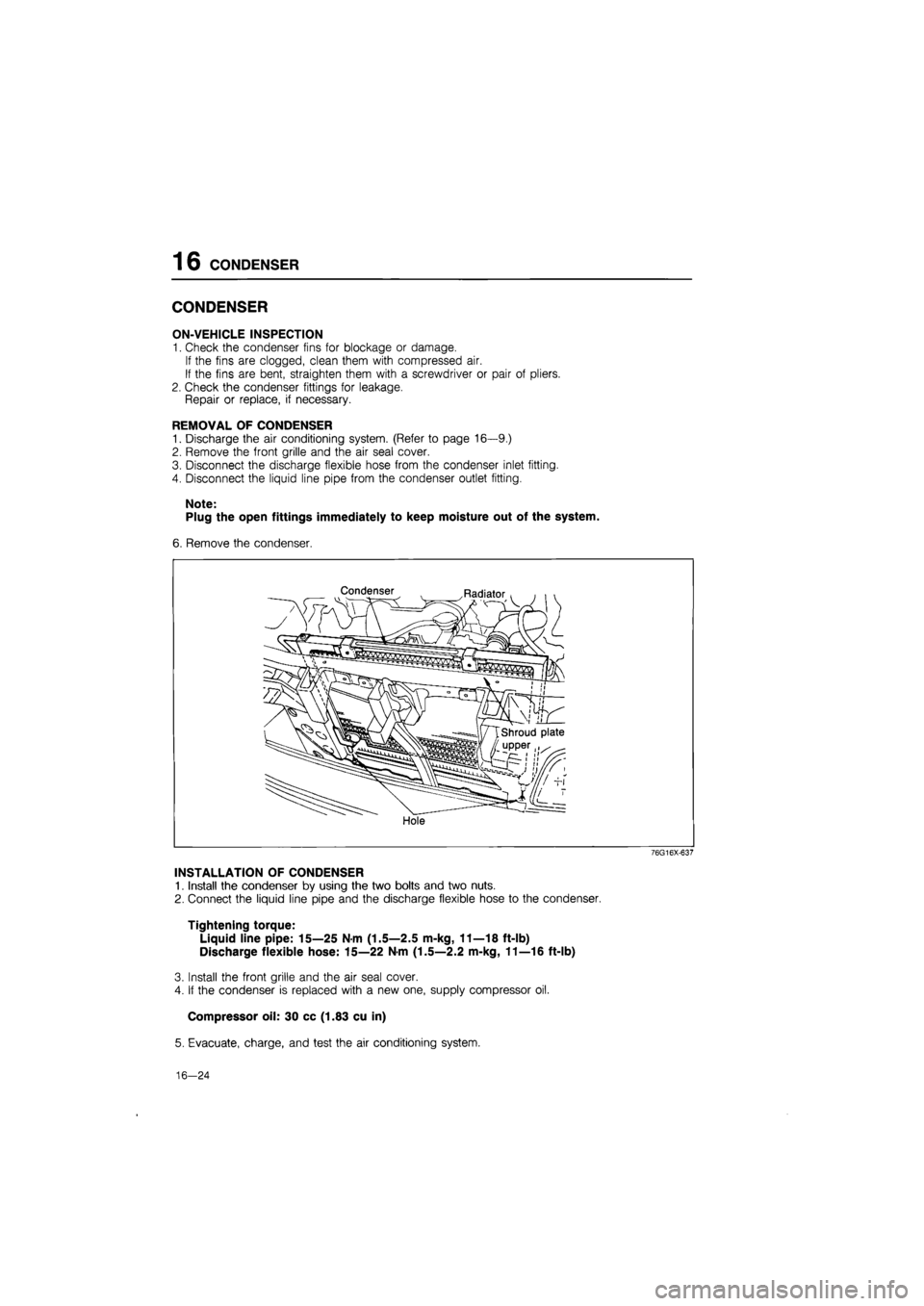
6. Remove the condenser.
Condenser Radiator
Hole
76G16X-637
INSTALLATION OF CONDENSER
1. Install the condenser by using the two bolts and two nuts.
2. Connect the liquid line pipe and the discharge flexible hose to the condenser.
Tightening torque:
Liquid line pipe: 15—25 Nm (1.5—2.5 m-kg, 11—18 ft-lb)
Discharge flexible hose: 15—22 N-m (1.5—2.2 m-kg, 11—16 ft-lb)
3. Install the front grille and the air seal cover.
4. If the condenser is replaced with a new one, supply compressor oil.
Compressor oil: 30 cc (1.83 cu in)
5. Evacuate, charge, and test the air conditioning system.
16—24
Page 1808 of 1865

RECEIVER-DRIER 16
RECEIVER-DRIER
ON-VEHICLE INSPECTION
1. Use a leak detector to check the sight glass, the
fusible plug, and the fittings for leakage.
Repair or replace, if necessary.
2. Check the receiver-drier for clogging.
a) Run the engine at fast idle with the air conditioner
on.
b) Check both inlet and outlet temperatures.
If there is a great difference between the two tem-
peratures, replace the receiver-drier.
76G16X-622
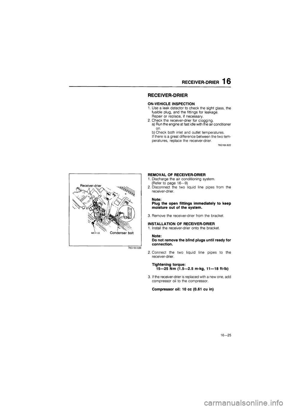
Receiver-drier
Condenser bolt
76G16X-638
REMOVAL OF RECEIVER-DRIER
1. Discharge the air conditioning system.
(Refer to page 16—9)
2. Disconnect the two liquid line pipes from the
receiver-drier.
Note:
Plug the open fittings immediately to keep
moisture out of the system.
3. Remove the receiver-drier from the bracket.
INSTALLATION OF RECEIVER-DRIER
1. Install the receiver-drier onto the bracket.
Note:
Do not remove the blind plugs until ready for
connection.
2. Connect the two liquid line pipes to the
receiver-drier.
Tightening torque:
15—25 N m (1.5—2.5 m-kg, 11—18 ft-lb)
3.
If
the receiver-drier is replaced with a new one, add
compressor oil to the compressor.
Compressor oil: 10 cc (0.61 cu in)
16-25
Page 1860 of 1865
40 SPECIAL TOOLS
AUTOMATIC TRANSAXLE
TOOL NUMBER & DESCRIPTION PRIORITY ILLUSTRATION
49 G019 0A7A
Compressor set, Return spring
A
49 G019 0A5A
Shim selector set A
a
x|mJen
It
49 0378 400A
Gauge set,
oil
pressure
A
lal
49 G019 011
Bearing installer A
mm H
49 FT01
376
Lifter, servo
piston
(3AT)
A
49 S120 785
Dsut boots
installer
A
49 FT01
377
Replacer,
low
reverse piston (3A1)
A
fl
jr "
49 FT 01
374
Holder,
one
way clutch position (3AT1
A
TOOL NUMBER & DESCRIPTION PRIORITY ILLUSTRATION
49 G032 355
Adjust gauge (3 AT) B
49 G019 9A2
Tester set, EC-AT
(EC-AT)
A
J3||
i®
49 G019 013
Bearing
remover
A
©5
49 G019 022
Attachment
K
A
49 FT01
439
Holder, idle
gear shaft
A
49 G019 012
Leak checker A
I
49 G019 0A2
Turbine shaft holder A
•o
49 0378 375
Compressor, clutch spring (3AT)
A i
U
40-6
Page 1864 of 1865
40 SPECIAL TOOLS
CHECKER AND OTHER
TOOL NUMBER & DESCRIPTION
49 F018 001
Checker lamp
49 9200
163
Adapter
harness
49 G018 902
Injector
checker
49 0187 280
Oil pressure gauge
49 0305 870A
Tool set,
window
49 0839 285
Checker, fuel
and
thermometer
49 9200
020
V-ribbed belt tension gauge
49 0242 685A
Switch starter
PRIORITY ILLUSTRATION TOOL NUMBER & DESCRIPTION
49 9200
162
Monitor, engine signal
49 U018 003
Adapter harness
49 G018 901
Adapter
harness
49 9200 010
ACC checker
49 H018 9A1
Self-diagnosis
checker
49 9200 750A
Multi-pressure
tester
49 G018 001
Adapter harness
PRIORITY ILLUSTRATION
40—10 expert22 /yia http://rutracker.org