1987 MAZDA 626 check oil
[x] Cancel search: check oilPage 1530 of 1865
REAR SHOCK ABSORBER AND SPRING 1 3
86U13X062
86U13X-063
86U13X-064
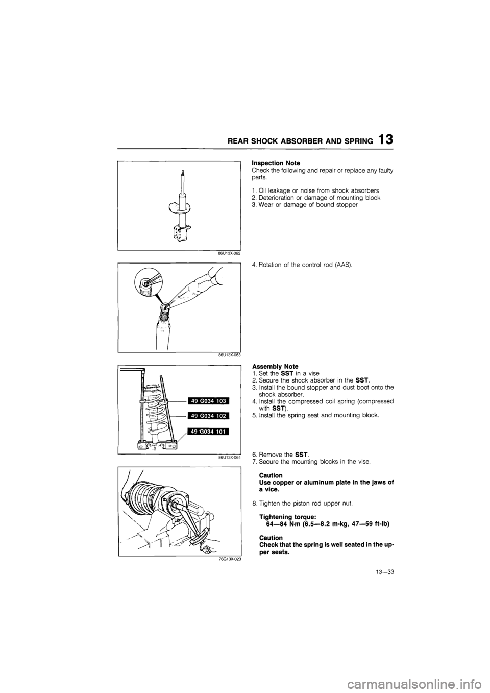
Inspection Note
Check the following and repair or replace any faulty
parts.
1. Oil leakage or noise from shock absorbers
2. Deterioration or damage of mounting block
3. Wear or damage of bound stopper
4. Rotation of the control rod (AAS).
Assembly Note
1. Set the SST in a vise
2. Secure the shock absorber in the SST.
3. Install the bound stopper and dust boot onto the
shock absorber.
4. Install the compressed coil spring (compressed
with SST).
5. Install the spring seat and mounting block.
6. Remove the SST.
7. Secure the mounting blocks in the vise.
Caution
Use copper or aluminum plate in the jaws of
a vice.
8. Tighten the piston rod upper nut.
Tightening torque:
64—84 N-m (6.5—8.2 m-kg, 47—59 ft-lb)
Caution
Check that the spring is well seated in the up-
per seats.
76G13X-023
13—33
Page 1660 of 1865
INTRODUCTION 15
69G15X-006
4BG15X-003
69G15X-007
/Wire
Shield braid wire
Insulation
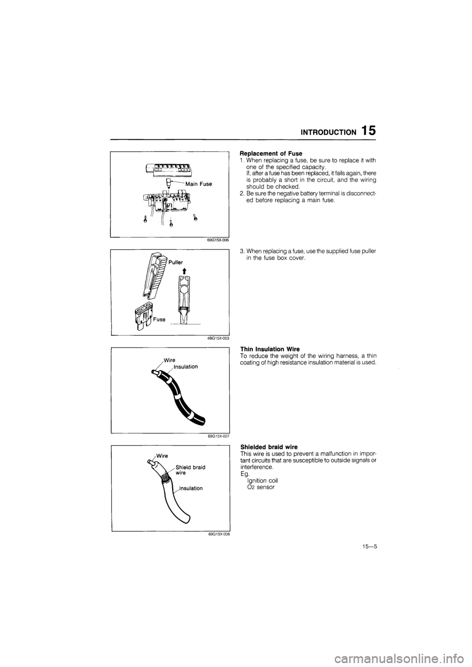
Replacement of Fuse
1. When replacing a fuse, be sure to replace it with
one of the specified capacity.
If, after a fuse has been replaced, it fails again, there
is probably a short in the circuit, and the wiring
should be checked.
2. Be sure the negative battery terminal is disconnect-
ed before replacing a main fuse.
3. When replacing a fuse, use the supplied fuse puller
in the fuse box cover.
Thin Insulation Wire
To reduce the weight of the wiring harness, a thin
coating of high resistance insulation material is used.
Shielded braid wire
This wire is used to prevent a malfunction in impor-
tant circuits that are susceptible to outside signals or
interference.
Eg.
Ignition coil
02 sensor
69G15X-008
15—5
Page 1695 of 1865
15 WARNING AND SENDER
86U15X-068
86U15X069
86U15X-070
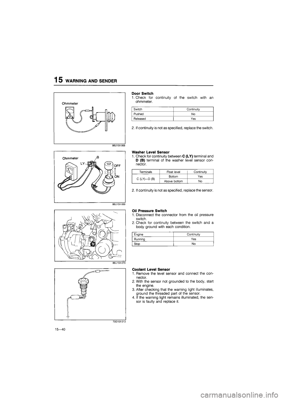
Door Switch
1. Check for continuity of the switch with an
ohmmeter.
2. If continuity is not as specified, replace the switch.
Washer Level Sensor
1. Check for continuity between C (LY) terminal and
D (B) terminal of the washer level sensor con-
nector.
Oil Pressure Switch
1. Disconnect the connector from the oil pressure
switch.
2. Check for continuity between the switch and a
body ground with each condition.
Coolant Level Sensor
1. Remove the level sensor and connect the con-
nector.
2. With the sensor not grounded to the body, start
the engine.
3. After checking that the warning light illuminates,
ground the threaded part of the sensor.
4. If the warning light remains illuminated, the sen-
sor is faulty and replace it.
73G15X-013
15—40
Engine Continuity
Running Yes
Stop No
Terminals Float level Continuity
C (LY)—D
(B)
Bottom Yes C (LY)—D
(B)
Above bottom No
2. If continuity is not as specified, replace the sensor.
Page 1739 of 1865
1 5 CRUISE CONTROL SYSTEM
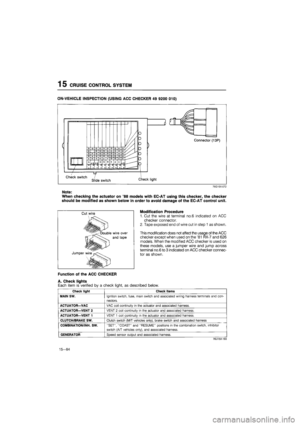
ON-VEHICLE INSPECTION (USING ACC CHECKER 49 9200 010)
76G15X-072
Note:
When checking the actuator on '88 models with EC-AT using this checker, the checker
should be modified as shown below in order to avoid damage of the EC-AT control unit.
Modification Procedure
1. Cut the wire at terminal no.6 indicated on ACC
checker connector.
2. Tape exposed end of wire cut in step 1 as shown.
This modification does not affect the usage of the ACC
checker except when used on the '81 RX-7 and 626
models. When the modified ACC checker is used on
these models, use a jumper wire and jump across
terminal no.6 to 3 indicated on ACC checker connec-
tor as shown.
Function of the ACC CHECKER
A. Check lights
Each item is verified by a check light, as described below.
Check light Check items
MAIN SW.
Ignition switch, fuse, main switch and associated wiring harness terminals and con-
nectors.
ACTUATOR—VAC
VAC coil continuity
in
the actuator and associated harness.
ACTUATOR—VENT 2
VENT
2
coil continuity
in
the actuator and associated harness.
ACTUATOR—VENT 1
VENT
1
coil continuity
in
the actuator and associated harness.
CLUTCH/BRAKE SW.
Clutch switch (M/T vehicles only), brake switch and associated harness
COMBINATION/INH. SW.
"SET", "COAST" and "RESUME" positions
in
the combination switch, inhibitor
switch (A/T vehicles only), and associated harness.
GENERATOR
Speed sensor output and associated harness.
76U15X-193
15-84
Page 1788 of 1865
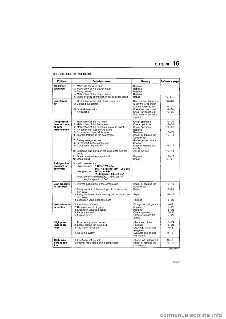
OUTLINE 16
TROUBLESHOOTING GUIDE
Problem Probable cause Remedy Reference page
No blower
1. Main fuse (30
A) is
open Replace
operation
2 Malfunction
of
the blower motor Replace 3. Faulty resistor Replace 4. Malfunction
of
the blower switch Replace 5. Open
or
loose connection
in an
electrical circuit Repair 16—6,
7
Insufficient
1. Obstruction
in
the inlet
of
the blower unit Remove the obstruction 16-26
air
2. Clogged evaporator Clean the evaporator
with compressed
air
16-27 3. Frosted evaporator Check the thermostat 16-30 4. Air leakage Check for leakage
at
16-26 both sides
of
the cool-
ing unit
Compressor
1. Malfunction
of
the A/C relay Check operation 16—30
does not run,
2. Malfunction
of
the thermostat Check operation 16—30
or runs
3. Malfunction
of
the refrigerant-pressure switch Check operation 16—31
insufficiently
4.
Air
conditioner fuse (15
A)
failure Replace 5. Compressor drive belt
is
loose Readjust 16—23
6. Internal problem
of
the compressor Repair
or
replace
the
16—13
compressor 7. Battery voltage too low Recharge the battery 8. Layer short
in
the magnet coil Replace 9. Clutch face dirty with
oil
Clean
or
replace the 16-13
clutch 10. Excessive gap between the drive plate and
the
Adjust the gap 16-13
pulley
11. Open circuit
in
the magnet coil Replace 16—13
12 Open circuit Repair 16-6,
7
Refrigeration
Normal pressures are:
pressure is
High pressure
1472—1765 kPa
abnormal (15—18 kg/cm2, 214—255 psi)
Low pressure
197—294 kPa
(2—3 kg/cm2, 29—42 psi)
when: ambient temperature 35°C (95°F)
engine speed 1,500
rpm
Low pressure
1. Internal malfunction
of
the compressor Repair
or
replace the 16-13
is too high
compressor
2. Faulty contact
of
the sensing bulb
of
the expan-Repair 16-26
sion valve 3. Faulty insulation
of
the sensing bulb
of
the expan-Repair 16—26
sion valve
4. Expansion valve open too much Replace 16—26
Low pressure
1. Insufficient refrigerant Charge with refrigerant 16-8
is too low
2. Receiver-drier
is
clogged Replace 16-25
3. Expansion valve
is
clogged Replace 16-26
4. Faulty thermostat Check operation 16-30 5. Frosted piping Clean
or
replace the 16—29
piping
High pres-
1. Poor cooling
of
condenser Check and clean 16-24
sure is too
2. Loose cooling fan drive belt Readjust 16—23
high
3. Too much refrigerant Discharge the excess 16-8
refrigerant 4.
Air in
the system Evacuate and charge 16-8
the system
High pres-
1. Insufficient refrigerant Charge with refrigerant 16-8
sure is too
2. Internal malfunction
of
the compressor Repair
or
replace the 16-13
low
compressor
76G16X-004
16—5
Page 1792 of 1865
OUTLINE 16
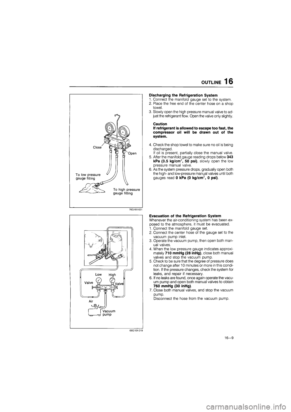
Discharging the Refrigeration System
1. Connect the manifold gauge set to the system.
2. Place the free end of the center hose on a shop
towel.
3. Slowly open the high pressure manual valve to ad-
just the refrigerant flow. Open the valve only slightly.
Caution
If refrigerant is allowed to escape too fast, the
compressor oil will be drawn out of the
system.
4. Check the shop towel to make sure no oil is being
discharged.
If oil is present, partially close the manual valve.
5. After the manifold gauge reading drops below 343
kPa (3.5 kg/cm2, 50 psi), slowly open the low
pressure manual valve.
6. As the system pressure drops, gradually open both
the high- and low-pressure manual valves until both
gauges read 0 kPa (0 kg/cm2, 0 psi).
76G16X-631
Evacuation of the Refrigeration System
Whenever the air-conditioning system has been ex-
posed to the atmosphere, it must be evacuated.
1. Connect the manifold gauge set.
2. Connect the center hose of the gauge set to the
vacuum pump inlet.
3. Operate the vacuum pump, then open both man-
ual valves.
4. When the low pressure gauge indicates approxi-
mately 710 mmHg (28 inHg), close both manual
valves and stop the vacuum pump.
5. Check to be sure that the degree of pressure does
not change after 10 minutes or more in this condi-
tion.
If
the pressure changes, check the system for
leaks, and repair if necessary.
6. If no leaks are found, once again operate the vacu-
um pump and open both manual valves to obtain
760 mmHg (30 inHg).
7. Close both manual valves, and stop the vacuum
pump.
Disconnect the hose from the vacuum pump.
69G16X-019
16-9
Page 1796 of 1865
COMPRESSOR 16
69G16X-026
M10X1.25^45
Low-pressure x pressure
hose hose Compressor
COMPRESSOR
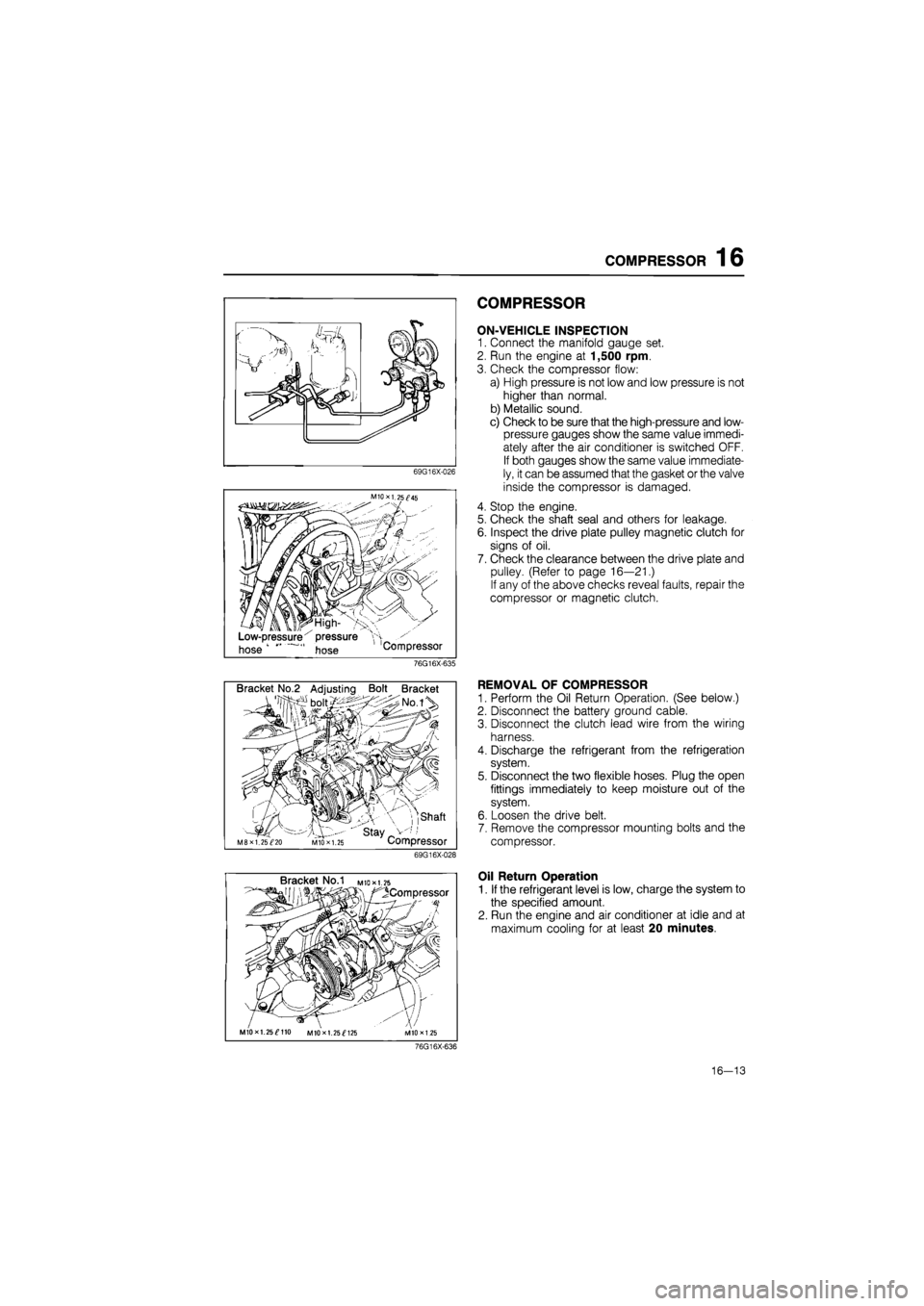
ON-VEHICLE INSPECTION
1. Connect the manifold gauge set.
2. Run the engine at 1,500 rpm.
3. Check the compressor flow:
a) High pressure is not low and low pressure is not
higher than normal.
b) Metallic sound.
c) Check to be sure that the high-pressure and low-
pressure gauges show the same value immedi-
ately after the air conditioner is switched OFF.
If both gauges show the same value immediate-
ly, it can be assumed that the gasket or the valve
inside the compressor is damaged.
4. Stop the engine.
5. Check the shaft seal and others for leakage.
6. Inspect the drive plate pulley magnetic clutch for
signs of oil.
7. Check the clearance between the drive plate and
pulley. (Refer to page 16—21.)
If any of the above checks reveal faults, repair the
compressor or magnetic clutch.
76G16X-635
Bracket No.2 Adjusting Bolt Bracket
, ,shaft
' stay _ M8XI. 25^20 MIO X 1.25 Compressor
69G16X-028
REMOVAL OF COMPRESSOR
1. Perform the Oil Return Operation. (See below.)
2. Disconnect the battery ground cable.
3. Disconnect the clutch lead wire from the wiring
harness.
4. Discharge the refrigerant from the refrigeration
system.
5. Disconnect the two flexible hoses. Plug the open
fittings immediately to keep moisture out of the
system.
6. Loosen the drive belt.
7. Remove the compressor mounting bolts and the
compressor.
Bracket No.1 M
to* 1.25
^Compressor
MIOxl. 25^110 MIOxl. 25^125
Oil Return Operation
1. If the refrigerant level is low, charge the system to
the specified amount.
2. Run the engine and air conditioner at idle and at
maximum cooling for at least 20 minutes.
76G16X-636
16—13
Page 1798 of 1865
COMPRESSOR 16
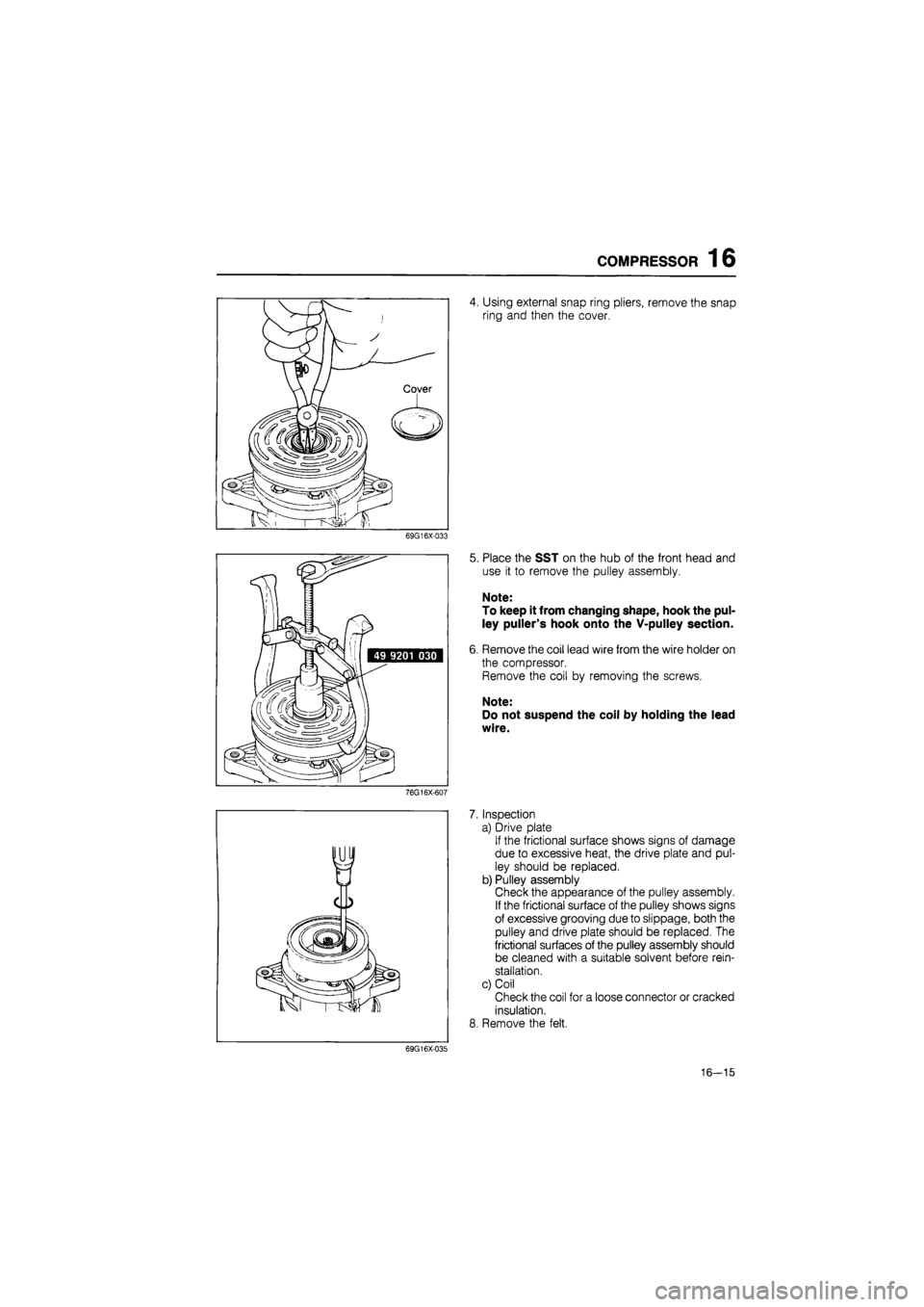
4. Using external snap ring pliers, remove the snap
ring and then the cover.
69G16X-033
7.
8.
69G16X-035
Place the SST on the hub of the front head and
use it to remove the pulley assembly.
Note:
To keep it from changing shape, hook the pul-
ley puller's hook onto the V-pulley section.
Remove the coil lead wire from the wire holder on
the compressor.
Remove the coil by removing the screws.
Note:
Do not suspend the coil by holding the lead
wire.
Inspection
a) Drive plate
If the frictional surface shows signs of damage
due to excessive heat, the drive plate and pul-
ley should be replaced.
b) Pulley assembly
Check the appearance of the pulley assembly.
If the frictional surface of the pulley shows signs
of excessive grooving due to slippage, both the
pulley and drive plate should be replaced. The
frictional surfaces of the pulley assembly should
be cleaned with a suitable solvent before rein-
stallation.
c) Coil
Check the coil for a loose connector or cracked
insulation.
Remove the felt.
16—15