Page 1485 of 1865
ANTI-LOCK BRAKE SYSTEM (ABS) 1 1
Installation of Rear Sensor Rotor
Install in the reverse order of removal, referring to installation note for the specially marked parts.
Torque specifications
86U11X-184
Installation
Sensor rotor
Press the sensor rotor onto the hub with the SST.
86U11X-185
Locknut
1. Install and tighten the locknut.
2. Stake a new locknut securely in the driveshaft
groove.
Caution
Do not use a pointed tool for staking.
3. Check that the hub rotates freely by hand.
86U11X-186
11—93
Page 1491 of 1865

ANTI-LOCK BRAKE SYSTEM (ABS) 1 1
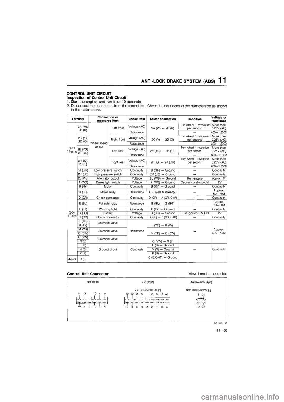
CONTROL UNIT CIRCUIT
Inspection of Control Unit Circuit
1. Start the engine, and run it for 10 seconds.
2. Disconnect the connectors from the control unit. Check the connector at the harness side as shown
in the table below.
Terminal Connection or measured item Check item Tester connection Condition Voltage or
resistance
Q-01 11 -pins
2A (W),
2B (R)
Wheel speed sensor
Left front Voltage (AC) 2A (W)
- 2B
(R) Turn wheel
1
revolution
per second More than 0.25V (AC)
Q-01 11 -pins
2A (W),
2B (R)
Wheel speed sensor
Left front
Resistance
2A (W)
- 2B
(R)
—
800-1.2000
Q-01 11 -pins
2C (Y),
2D
(0)
Wheel speed sensor
Right front Voltage (AC) 2C (Y)
-
2D (0) Turn wheel
1
revolution
per second More than 0.25V (AC)
Q-01 11 -pins
2C (Y),
2D
(0)
Wheel speed sensor
Right front
Resistance
2C (Y)
-
2D (0)
—
800-1,2000
Q-01 11 -pins 2E (YG),
2F (YL)
Wheel speed sensor
Left rear Voltage (AC) 2E (YG)
- 2F
(YL) Turn wheel
1
revolution
per second More than 0.25V (AC) Q-01 11 -pins 2E (YG),
2F (YL)
Wheel speed sensor
Left rear
Resistance
2E (YG)
- 2F
(YL)
—
800-1,200G
Q-01 11 -pins
2H (G).
2J
(L)
Wheel speed sensor
Right rear Voltage (AC) 2H (G)
- 2J
(GR)
Turn wheel
1
revolution
per second More than 0.25V (AC)
Q-01 11 -pins
2H (G).
2J
(L)
Wheel speed sensor
Right rear
Resistance
2H (G)
- 2J
(GR)
_
800-1,200fl
Q-01 11 -pins
21 (GR) Low pressure switch Continuity 21 (GR)
-
Ground
—
Continuity
Q-01 11 -pins
2K (LB) High pressure switch Continuity 2K (LB)
-
Ground
—
Continuity
Q-01 11 -pins
2L (WB) Alternator output Voltage 2L (WB)
-
Ground Run engine Approx.
14V
Q-01
17-pins
A (WG) Brake light switch Voltage A (WG)
-
Ground Depress brake pedal 12V
Q-01
17-pins
B (RY) Motor Continuity B (RY)
—
Ground
—
Continuity
Q-01
17-pins
C (LO) Motor relay Resistance C (Lo)(© test-lead)-J
—
Approx. 60—700
Q-01
17-pins
D (GR) Check connector Continuity D (GR)
- A
(GR, Q-07)
—
Continuity
Q-01
17-pins
E (BL) Fail-safe relay Resistance E (BL)
- G
(BG)
—
Approx. 70-800
Q-01
17-pins
F (LY) Warning light Continuity F (LY)
-
Ground
—
Continuitv Q-01
17-pins G (BG) Battery Voltage G (BG)
—
Ground Turn ianition
SW ON
12V Q-01
17-pins H (GB) Check connector Continuitv H (GB)
- B
(GB. Q-07)
—
Continuitv
Q-01
17-pins
J (YG) Solenoid valve
Resistance
JfYG)
- K
(Br)
-
Approx.
5.5—7.00
Q-01
17-pins
K (Br) Solenoid valve
Resistance
JfYG)
- K
(Br)
-
Approx.
5.5—7.00
Q-01
17-pins
M (YR) Solenoid valve Resistance M (YR)
- 0
(BW)
-
Approx.
5.5—7.00
Q-01
17-pins
0 (BW) Solenoid valve Resistance M (YR)
- 0
(BW)
-
Approx.
5.5—7.00
Q-01
17-pins
Q (YW) Solenoid valve
Resistance
Q (YW)
- R
(L)
-
Approx.
5.5—7.00
Q-01
17-pins
R (L) Solenoid valve
Resistance
Q (YW)
- R
(L)
-
Approx.
5.5—7.00
Q-01
17-pins
L (B)
Ground circuit Continuity
L (B)
—
Ground
Continuity
Q-01
17-pins
N
(B)
Ground circuit Continuity N (B)
—
Ground Continuity
Q-01
17-pins
P (B)
Ground circuit Continuity
P (B)
—
Ground
C (B.Q-07)
-
Ground
Continuity
4-pins C(B)
Ground circuit Continuity
P (B)
—
Ground
C (B.Q-07)
-
Ground
Continuity
Control Unit Connector View from harness side
Q-01 (11-pin)
LB
GR YG Y W
>1 ,1 U;.l Ki -X
1 L G VL rf
Q-01 (17-pin)
Q-01 ABS Control Unit [R]
YW BW YR Br 8G BL LO WG
icL olL
MIL
ICL G(=L tl ij^" llyl
>1
CjJ
Lt|J JCjJ fiC|3 H«|3
L B B B ffi SB L* GS RY
Check connector (4-pin)
Q-07 Check Connector [RJ
B GR
LY GB
86U11X-199
11—99
Page 1660 of 1865
INTRODUCTION 15
69G15X-006
4BG15X-003
69G15X-007
/Wire
Shield braid wire
Insulation
Replacement of Fuse
1. When replacing a fuse, be sure to replace it with
one of the specified capacity.
If, after a fuse has been replaced, it fails again, there
is probably a short in the circuit, and the wiring
should be checked.
2. Be sure the negative battery terminal is disconnect-
ed before replacing a main fuse.
3. When replacing a fuse, use the supplied fuse puller
in the fuse box cover.
Thin Insulation Wire
To reduce the weight of the wiring harness, a thin
coating of high resistance insulation material is used.
Shielded braid wire
This wire is used to prevent a malfunction in impor-
tant circuits that are susceptible to outside signals or
interference.
Eg.
Ignition coil
02 sensor
69G15X-008
15—5
Page 1662 of 1865
LOCATION OF UNIT, RELAY AND SWITCH 1 5
LOCATION OF
UNIT,
RELAY AND SWITCH
STRUCTURAL VIEW
Door SW
Power window SW
AAS control unit
Cruise control unit
Relay box
(EGI and Diesel model)
Engine control unit
Brake fluid level sensor
Main fuse block
(EGI model)
Main fuse block
(Carburetor model) | \ Relay box
Main fuse block Relay box
(Diesel model) (Carburetor model)
Power window SW
Door SW
Door lock SW
AAS control SW
CPU and joint box
86U15X-002
15-7
Page 1667 of 1865
1 5 COMBINATION SWITCH
CONBINATION SWITCH
STRUCTURAL VIEW
Left hand drive
Alignment mark
Right hand drive
Alignment mark
76G15X-002
1. Light and turn signal switch lever
2. Windshield wiper and washer switch lever
3. Cruise control switch
4. Steering angle sensor
5. Hazard switch
6. Light switch connectors
7. Turn signal switch connector
8. Windshield wiper and washer switch con-
nector
9. Steering angle sensor connector
10. Turn signal and hazard switch connector
15—12
Page 1671 of 1865

1 5 COMBINATION SWITCH
Steering angle sensor
Terminal Steering wheel position Resistance value
AO
to
AR Turn the wheel
a
little
at
a
time from
the
straight-ahead posi-
tion 180° to the right.
Decreases from about
25 kfi to about 200
fl.
AO
to
AR Straight-ahead position About
25 kfi
AO
to
AR Turn the wheel
a
little at
a
time from
the
straight-ahead posi-tion 180°
to
the left.
Increases from about 25 kfl to about 50 kfl.
AL
to
AR Straight-ahead position About
50 kfi
86U15X-014
—
i 50kn k Resistance
25M?
2000
" 180° 0° 180° " To the left To the right
86U15X-015
Note
When the steering wheel is turned more than
the specified angle in the above test, the re-
sistance value will become as shown in the
table below.
Terminal Steering wheel position Resistance value
AO
to
AR When turned 180°
or
more to the right from the straight-ahead po-sition.
Resistance slowly and gradually decreases after there
is
once
an
indication of about 50 kfl.
AO
to
AR When turned 180°
or
more
to
the left from
the straight-ahead po-
sition.
Resistance slowly and gradually increases after there
is
once
an
indication
of
about 200
fl.
15—16
Page 1682 of 1865
![MAZDA 626 1987 Workshop Manual
METER 15
86U15X-033
86U15X-034
104.1t! 21
2330 16.10
a £] U \JEMP j n
JJ
86U15X-035
Standard indication
(km/h)
Allowable range
(km/h)
60 60-63
Standard indication
(mph)
Allowable ran MAZDA 626 1987 Workshop Manual
METER 15
86U15X-033
86U15X-034
104.1t! 21
2330 16.10
a £] U \JEMP j n
JJ
86U15X-035
Standard indication
(km/h)
Allowable range
(km/h)
60 60-63
Standard indication
(mph)
Allowable ran](/manual-img/28/57059/w960_57059-1681.png)
METER 15
86U15X-033
86U15X-034
104.1t! 21
2330 16.10
a £] U \JEMP j n
JJ
86U15X-035
Standard indication
(km/h)
Allowable range
(km/h)
60 60-63
Standard indication
(mph)
Allowable range
(mph)
60 60-63
86U15X-036
3. Set the SST to the resistance values shown in the
figure.
4. Turn the ignition switch ON, and check that the
needle indicator displays the correct values.
If the needle displays correctly, check the gauge
unit. If not, replace the fuel gauge in the meter or
repair the wiring harness.
Caution
a) Continue the above checks for at least two
minutes each to correctly judge the con-
dition.
b)The allowable indication error is twice the
width of the needle.
Water Temperature Gauge
1. Disconnect the connector from the water thermo
sensor.
2. Connect the red lead of the SST to the connec-
tor, and the black lead to a body ground.
3. Set the SST to the resistance values shown in the
figure.
4. Turn the ignition switch ON, and check that the
needle indicator displays the correct values.
If the needle displays the correct values, the trou-
ble is in the gauge unit; if not, the trouble is in the
meter or the wiring harness.
Caution
a) Continue the above checks for at least two
minutes each to correctly judge the con-
dition.
b)The allowable indication error is twice the
width of the needle.
INSPECTION OF DIGITAL METER
Speedometer
1. Using a speedometer tester, check the speedom-
eter for allowable indication error, and check the
operation of the odometer. Replace the meter as-
sembly if necessary.
2. Check the speedometer for fluctuation and/or ab-
normal noise.
Caution
a) If significant fluctuation occurs or the
speedometer does not move at all, remove
the speedometer cable. If normal, replace
the digital meter assembly.
b)Tire wear and improper inflation will in-
crease speedometer error.
15—27
Page 1684 of 1865

METER 15
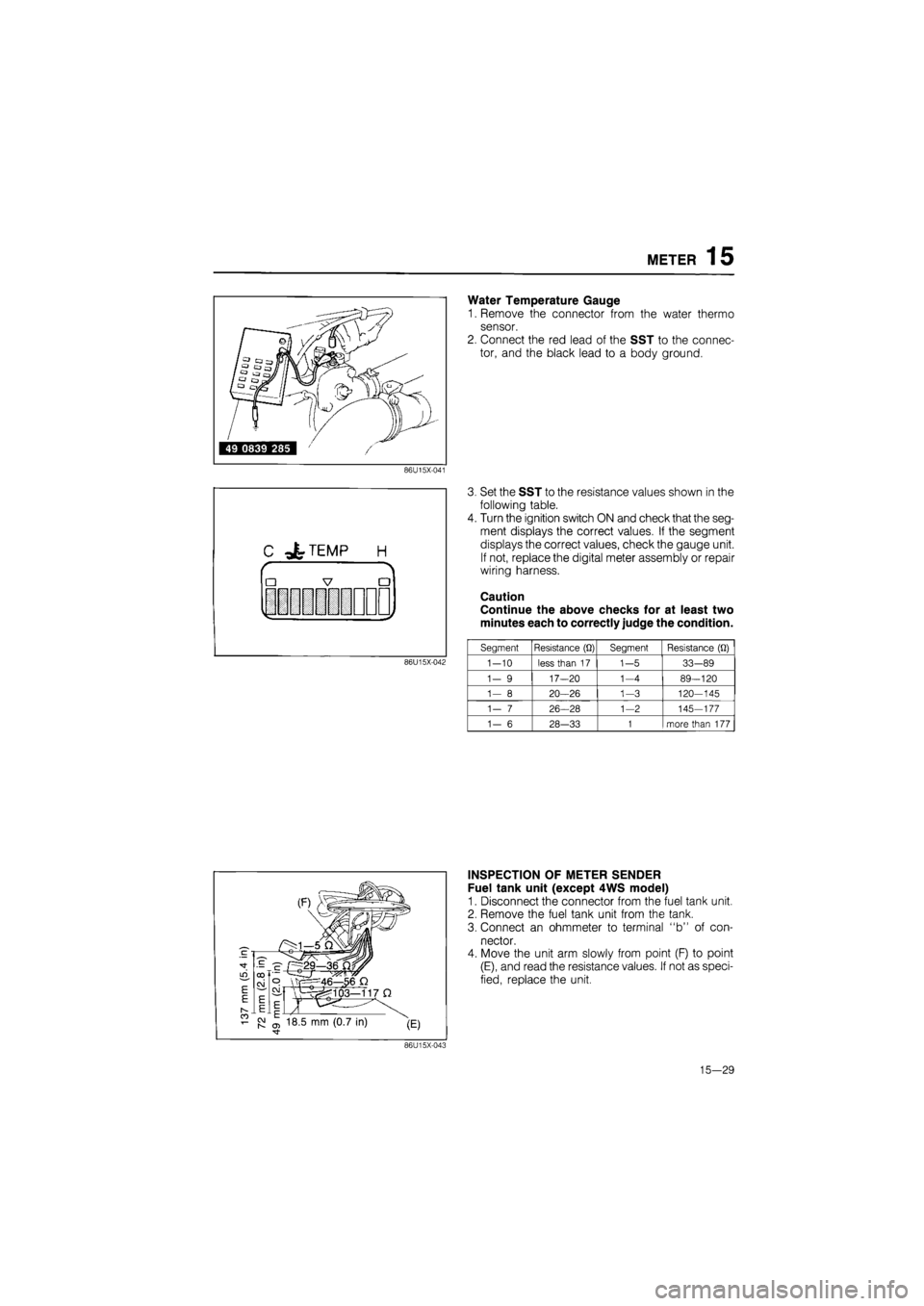
Water Temperature Gauge
1. Remove the connector from the water thermo
sensor.
2. Connect the red lead of the SST to the connec-
tor, and the black lead to a body ground.
86U15X-041
C -&TEMP H
r
•
|
7 •
V i y
86U15X-042
3. Set the SST to the resistance values shown in the
following table.
4. Turn the ignition switch ON and check that the seg-
ment displays the correct values. If the segment
displays the correct values, check the gauge unit.
If not, replace the digital meter assembly or repair
wiring harness.
Caution
Continue the above checks for at least two
minutes each to correctly judge the condition.
Segment Resistance
(Q)
Segment Resistance
(Q)
1-10
less than
17
1-5
33-89
1-
9
17—20
1-4
89-120
1—
8
20—26
1-3
120-145
1—
7
26-28
1-2
145-177
1-
6
28-33
1
more than
177
INSPECTION OF METER SENDER
Fuel tank unit (except 4WS model)
1. Disconnect the connector from the fuel tank unit.
2. Remove the fuel tank unit from the tank.
3. Connect an ohmmeter to terminal "b" of con-
nector.
4. Move the unit arm slowly from point (F) to point
(E), and read the resistance values. If not as speci-
fied, replace the unit.
86U15X-043
15—29