Page 1384 of 1865
1 0 ELECTRICAL COMPONENTS OF 4-WHEEL STEERING
Condition B
1. Place the vehicle on a chassis roller tester. Block
the rear wheels, and secure it with chains.
2. Turn the ignition switch OFF.
3. Start the engine after the ignition switch has been
OFF for at least 10 seconds. Put the transmission
in gear and operate the vehicle at more than 40
km/h (25 mph).
4. Check if the 4WS warning light flashes or il-
luminates within 60 seconds.
5.
If
flashing or illumination occurs, inspect the circuit
by referring to the table below.
76G10X045
Diagnosis Output Pattern
Warning light output pattern
0.5 sec —i 2.5 sec
Malfunction
Normal operation, control unit or wir-ing harness
Speed sensors or
wiring harness
Flow chart
No.
4WS—0
4WS—1
Rear steering gear
assembly
Solenoid valve or wiring harness
Stepper motor or wiring harness
Rear-to-front steer-ing ratio sensor or wiring harness
4WS—2
4WS—3
4WS—4
4WS—5
86U10X-225
10-96
Page 1386 of 1865
1 0 ELECTRICAL COMPONENTS OF 4-WHEEL STEERING
4WS-0 Normal operation or failure of con-trol unit or harness
Start engine.
Disconnect R-01 (7-pin) connector. Check that 4WS warning light flashes or illuminates.
NG
Repair harness. (Fuse box to Control unit or Control unit to Body ground).
YES No electrical problem.
NO
Reconnect connector.
Check voltage between terminals and body ground.
Terminal Voltage
G(B) OV
H(B) OV
K(G) Approx. 12V
L(G) Approx. 12V
N(B) OV
OK Replace control unit.
4WS-1 Failure of speed sensors or wiring
harness
Check speed sensor at transaxle. (Referring to page 10—103)
OK
NG Replace speed sensor.
Check for continuity between terminal of transaxle speed sensor and R (O) terminal of the control unit connector.
NG^ Repair wiring harness (Control unit to Transaxle
speed sensor).
Cont'd 76G10X-028
10—98
Page 1388 of 1865

1 0 ELECTRICAL COMPONENTS OF 4-WHEEL STEERING
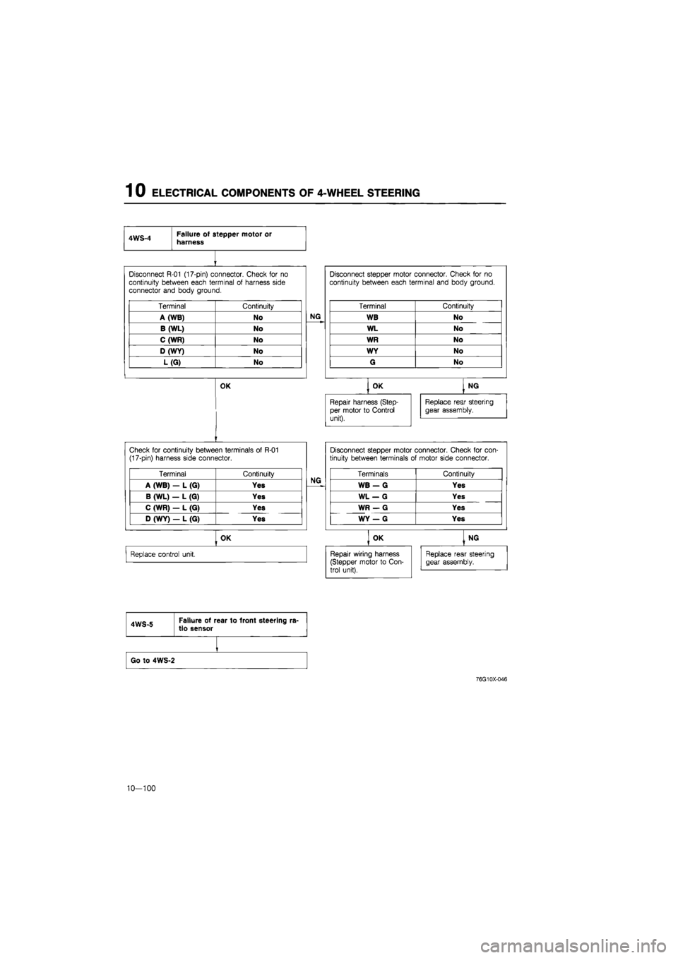
awq a Failure of stepper motor or harness
Disconnect R-01 (17-pin) connector. Check for no
continuity between each terminal of harness side
connector and body ground.
NG
Disconnect stepper motor connector. Check for no
continuity between each terminal and body ground.
Terminal Continuity
NG
Terminal Continuity
A (WB) No NG WB No
B (WL) No WL No
C (WR) No WR No
D (WY) No WY No
L(G) No G No
OK , OK | NG OK
Repair harness (Step-
per motor to Control
unit).
Replace rear steering
gear assembly.
Check for continuity between terminals of R-01
(17-pin) harness side connector.
NG
Disconnect stepper motor connector. Check for con-tinuity between terminals of motor side connector.
Terminal Continuity NG Terminals Continuity
A (WB) - L (G) Yes NG WB — G Yes
B (WL) — L (G) Yes
NG
WL — G Yes
C (WR) — L (G) Yes
NG
WR — G Yes
D (WY) — L (G) Yes
NG
WY — G Yes
NG
OK OK | NG
Replace control unit. Repair wiring harness (Stepper motor to Con-trol unit).
Replace rear steering gear assembly.
Repair wiring harness (Stepper motor to Con-trol unit).
Replace rear steering gear assembly.
4WS-5 Failure of rear to front steering ra-
tio sensor
Go to 4W5-2
76G10X-046
10-100
Page 1389 of 1865
ELECTRICAL COMPONENTS OF 4-WHEEL STEERING 1 0
4WS-6 Failure of rear to front steering ra-tio sensor or harness
Start engine.
I
Check voltage between control unit terminal and body ground.
OK
Check voltage between control unit terminal and body ground.
Terminal Resistance
2F (GO) Approx. 5.0 V
NG Replace control unit.
Terminal Resistance
2G (GW) Approx. 4.5 V
OK Replace control unit.
NG
Check rear to front ratio sensor (Refer to page 10-103).
NG Replace rear steering gear assembly
OK
Repair harness (Control unit to Sensor).
Flashes or illuminates
Check voltage between 0(Y) terminal of R-01 (17-pin)
connector and a body ground.
Terminal Voltage
0(Y) 0 V
OK Replace control unit.
NG
10-101
Page 1391 of 1865

ELECTRICAL COMPONENTS OF 4-WHEEL STEERING 1 0
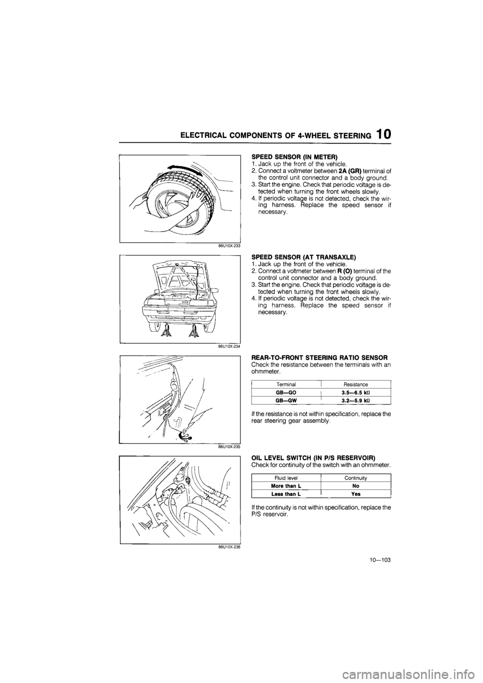
SPEED SENSOR (IN METER)
1. Jack up the front of the vehicle.
2. Connect a voltmeter between 2A (GR) terminal of
the control unit connector and a body ground.
3. Start the engine. Check that periodic voltage is de-
tected when turning'the front wheels slowly.
4. If periodic voltage is not detected, check the wir-
ing harness. Replace the speed sensor if
necessary.
86U10X-233
SPEED SENSOR (AT TRANSAXLE)
1. Jack up the front of the vehicle.
2. Connect a voltmeter between R (O) terminal of the
control unit connector and a body ground.
3. Start the engine. Check that periodic voltage is de-
tected when turning the front wheels slowly.
4. If periodic voltage is not detected, check the wir-
ing harness. Replace the speed sensor if
necessary.
86U10X-234
REAR-TO-FRONT STEERING RATIO SENSOR
Check the resistance between the terminals with an
ohmmeter.
Terminal [ Resistance
GB—GO l 3.5—6.5 kfi
GB—GW ' 3.2—5.9 kfi
If
the resistance is not within specification, replace the
rear steering gear assembly.
86U10X-235
OIL LEVEL SWITCH (IN P/S RESERVOIR)
Check for continuity of the switch with an ohmmeter.
Fluid level Continuity
More than L No
Less than L Yes
If
the continuity is not within specification, replace the
P/S reservoir.
86U10X-236
10—103
Page 1393 of 1865

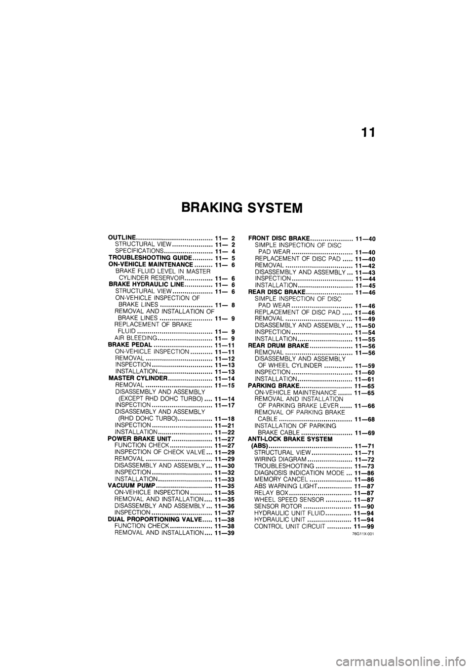
11
BRAKING SYSTEM
OUTLINE 11—2
STRUCTURAL VIEW 11—2
SPECIFICATIONS 11— 4
TROUBLESHOOTING GUIDE 11— 5
ON-VEHICLE MAINTENANCE 11—6
BRAKE FLUID LEVEL IN MASTER
CYLINDER RESERVOIR 11— 6
BRAKE HYDRAULIC LINE 11—6
STRUCTURAL VIEW 11—6
ON-VEHICLE INSPECTION OF
BRAKE LINES 11— 8
REMOVAL AND INSTALLATION OF
BRAKE LINES 11— 9
REPLACEMENT OF BRAKE
FLUID 11— 9
AIR BLEEDING 11— 9
BRAKE PEDAL 11—11
ON-VEHICLE INSPECTION 11—11
REMOVAL 11—12
INSPECTION 11—13
INSTALLATION 11—13
MASTER CYLINDER 11—14
REMOVAL 11—15
DISASSEMBLY AND ASSEMBLY
(EXCEPT RHD DOHC TURBO).... 11—14
INSPECTION 11—17
DISASSEMBLY AND ASSEMBLY
(RHD DOHC TURBO) 11—18
INSPECTION 11—21
INSTALLATION 11—22
POWER BRAKE UNIT 11—27
FUNCTION CHECK 11—27
INSPECTION OF CHECK VALVE... 11—29
REMOVAL 11—29
DISASSEMBLY AND ASSEMBLY... 11—30
INSPECTION 11—32
INSTALLATION 11—33
VACUUM PUMP 11—35
ON-VEHICLE INSPECTION 11—35
REMOVAL AND INSTALLATION.... 11—35
DISASSEMBLY AND ASSEMBLY... 11—36
INSPECTION 11—37
DUAL PROPORTIONING VALVE 11—38
FUNCTION CHECK 11—38
REMOVAL AND INSTALLATION.... 11—39
FRONT DISC BRAKE 11—40
SIMPLE INSPECTION OF DISC
PAD WEAR 11—40
REPLACEMENT OF DISC PAD 11—40
REMOVAL 11—42
DISASSEMBLY AND ASSEMBLY... 11—43
INSPECTION 11—44
INSTALLATION 11—45
REAR DISC BRAKE 11—46
SIMPLE INSPECTION OF DISC
PAD WEAR 11—46
REPLACEMENT OF DISC PAD 11—46
REMOVAL 11—49
DISASSEMBLY AND ASSEMBLY... 11—50
INSPECTION 11—54
INSTALLATION 11—55
REAR DRUM BRAKE 11—56
REMOVAL 11—56
DISASSEMBLY AND ASSEMBLY
OF WHEEL CYLINDER 11—59
INSPECTION 11—60
INSTALLATION 11—61
PARKING BRAKE 11—65
ON-VEHICLE MAINTENANCE 11—65
REMOVAL AND INSTALLATION
OF PARKING BRAKE LEVER 11—66
REMOVAL OF PARKING BRAKE
CABLE 11—68
INSTALLATION OF PARKING
BRAKE CABLE 11—69
ANTI-LOCK BRAKE SYSTEM
(ABS) 11—71
STRUCTURAL VIEW 11—71
WIRING DIAGRAM 11—72
TROUBLESHOOTING 11—73
DIAGNOSIS INDICATION MODE ... 11—86
MEMORY CANCEL 11—86
ABS WARNING LIGHT 11—87
RELAY BOX 11—87
WHEEL SPEED SENSOR 11—87
SENSOR ROTOR 11—90
HYDRAULIC UNIT FLUID 11—94
HYDRAULIC UNIT 11—94
CONTROL UNIT CIRCUIT 11—99
76G11X-001
Page 1395 of 1865
OUTLINE 11
86U11X-003
1. Front disc brake
2. Hydraulic unit
3. Pipe joint
4. Master cylinder
5. Power brake unit
6. Relay box
7. Control unit
8. Wheel speed sensor
9. Sensor rotor
10. Rear disc brake
11. Parking brake lever
12. Parking brake cable
Front disc brake
(Ventilated disc)
Rear disc brake
(Solid disc)
Rear drum brake
(Leading-trailing)
Page 1396 of 1865

1 1 OUTLINE
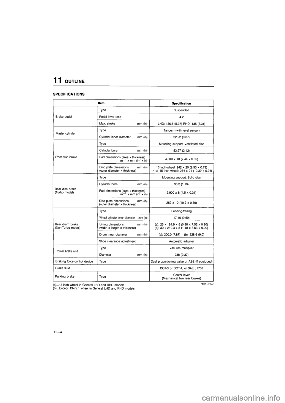
SPECIFICATIONS
Item Specification
Brake pedal
Type Suspended
Brake pedal Pedal lever ratio 4.2 Brake pedal
Max. stroke mm (in) LHD: 136.5 (5.37) RHD: 135 (5.31)
Master cylinder Type Tandem (with level sensor) Master cylinder
Cylinder inner diameter mm (in) 22.22 (0.87)
Front disc brake
Type Mounting support, Ventilated disc
Front disc brake
Cylinder bore mm (in) 53.97 (2.12)
Front disc brake Pad dimensions (area x thickness) mm2 x mm (in2 x in) 4,800 x 10 (7.44 x 0.39) Front disc brake
Disc plate dimensions mm (in) (outer diameter x thickness) 13 inch-wheel: 242 x 20 (9.53 x 0.79) 14 or 15 inch-wheel: 264 x 24 (10.39 x 0.94)
Rear disc brake
(Turbo model)
Type Mounting support, Solid disc
Rear disc brake
(Turbo model)
Cylinder bore mm (in) 30.2 (1.19)
Rear disc brake
(Turbo model) Pad dimensions (area x thickness) mm2 x mm (in2 x in) 2,900 x 8 (4.5 x 0.31)
Rear disc brake
(Turbo model)
Disc plate dimensions mm (in) (outer diameter x thickness) 259 x 10 (10.2 x 0.39)
Rear drum brake
(Non-Turbo model)
Type Leading-trailing
Rear drum brake
(Non-Turbo model)
Wheel cylinder inner diameter mm (in) 17.46 (0.69)
Rear drum brake
(Non-Turbo model) Lining dimensions mm (in)
(width x length x thickness) (a): 25 x 191.9 x 5 (0.98 x 7.56 x 0.20)
(b): 30 x 219.3 x 5 (1.18 x 8.63 x 0.20)
Rear drum brake
(Non-Turbo model)
Drum inner diameter mm (in) (a): 200.0 (7.87) (b): 228.6 (9.0)
Rear drum brake
(Non-Turbo model)
Shoe clearance adjustment Automatic adjuster
Power brake unit Type Vacuum multiplier Power brake unit
Diameter mm (in) 238 (9.37)
Braking force control device Type Dual proportioning valve or ABS (if equipped)
Brake fluid DOT-3 or DOT-4, or SAE J1703
Parking brake Type Center lever (Mechanical two rear brakes)
(a)...13-inch wheel in General LHD and RHD models
(b)...Except 13-inch wheel in General LHD and RHD models
11-4