Page 1270 of 1865
REAR AXLE 9
[Disc Brake]
REMOVAL (2WS)
Remove in the sequence shown in the figure.
1. Hub cap
2. Lock nut
3. Caliper assembly
4. Disc plate
5. Wheel speed sensor (ABS)
6. Dust cover
7. Trailing link
8. Lateral link
9. Shock absorber
10. Knuckle spindle
86U09X-039
9-21
Page 1271 of 1865
REAR AXLE
REMOVAL (4WS)
Remove in the sequence shown in the figure referring to the removal note for the specially marked parts.
86U09X-040
1. Hub cap 7. Control link
2. Lock nut 8. Wheel speed sensor (ABS)
3. Parking brake cable 9. Stabilizer bracket
4. Caliper assembly 10. Tie-rod end
5. Disc plate 11. Shock absorber
6. Dust cover 12. Knuckle spindle
Removal Note
Tie-rod end
Remove the tie-rod end from the knuckle spindle with
the SST.
86U09X-041
9-22
Page 1272 of 1865
REAR AXLE 9
DISASSEMBLY
Disassemble in the sequence shown in the figure referring to the disassembly note for the specially
marked parts.
1. Oil seal
2. Sensor rotor (ABS)
3. Retaining ring
4. Rear wheel bearing
5. Disc plate
86U09X-042
S 49 0839 425C
49 F027 007
86U09X-087
Disassembly Note
Note
a) Do not remove the hub bolts unless
necessary.
b)Do not reuse the hub bolts if removed.
Sensor rotor (ABS)
Remove the sensor rotor with the SST.
Note
a) Do not remove the sensor rotor unless
necessary.
b)Do not reuse the sensor rotor if removed.
Rear wheel bearing
Remove the rear wheel bearing with the SST.
Note
Do not reuse the rear wheel bearing if
removed.
86U09X-085
9-23
Page 1273 of 1865
INSPECTION
Check as described below, replace parts if necessary.
1. Check the hub for cracks or damage.
69G09X-028
2. Check the sensor rotor for cracks or damage.
69G09X-029
3. Check the knuckle spindle for cracks or damage,
and the oil seal friction surface for wear or rust.
86U09X-043
4. Check the dust cover for damage.
5. Check the hub cap for damage.
69G09X-031
Page 1274 of 1865
REAR AXLE 9
ASSEMBLY
1. Install new hub bolts.
86U09X-045
2. Install a new sensor rotor with the SST. (ABS)
86U09X-046
3. Install a new rear wheel bearing with the SST.
4. Install the retaining ring.
86U09X-047
5. Install a new oil seal with the SST.
Note
Apply grease to the oil seal lip.
86U09X-048
9—25
Page 1280 of 1865
DRIVESHAFT 9
[MTX]
DISASSEMBLY
Disassemble in the sequence shown in the figure referring to the disassembly note for specially marked
parts.
Note
a) Clamp the shaft in a vice. Use protectors in the vice to avoid damage.
b)Do not allow dirt or foreign matter in the joint during disassembly or assembly.
c) Do not disassemble the ball-joint at the wheel side. Do not wipe the grease off if there
is no problem.
d)Do not remove the clip used to secure the outer ring to the ball-joint at the differential
side if there is no problem.
If the clip is removed, replace it with a new one.
1. Boot band
2. Clip
3. Outer ring
4. Snap ring
86U09X-059
5. Ball joint
6. Boot band
7. Boot
8. Clip
9. Sensor rotor (Refer to Section 11)
Clip
1. Make matching marks on the driveshaft and out-
er ring for proper reassembly.
Note
Mark with paint, do not use a punch.
2. Remove the clip.
86U09X-091
9-31
Page 1284 of 1865
DRIVESHAFT 9
[ATX]
DISASSEMBLY
Disassemble in the sequence shown in the figure referring to the disassembly note for the specially
marked parts.
86U09X-064
1. Boot band 6. Boot band 9. Clip
2. Tripod joint assembly 7. Boot 10. Sensor rotor (Refer to Sec-
3. Boot band 8. Shaft and ball-joint as- tion 11)
4. Boot sembly
5. Boot band
Disassembly Note
Tripod joint assembly
1. Remove the snap ring using snap ring pliers, then
remove the tripod joint bearing.
2. Disassemble the joint shaft assembly.
86U09X-065
9-35
Page 1289 of 1865

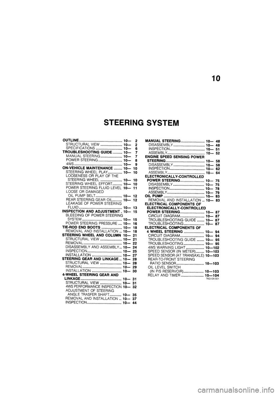
10
STEERING SYSTEM
OUTLINE 10— 2
STRUCTURAL VIEW 10— 2 SPECIFICATIONS 10— 6
TROUBLESHOOTING GUIDE 10— 7
MANUAL STEERING 10— 7
POWER STEERING 10— 8
4WS 10— 9
ON-VEHICLE MAINTENANCE 10— 10
STEERING WHEEL PLAY 10— 10
LOOSENESS OR PLAY OF THE
STEERING WHEEL 10— 10
STEERING WHEEL EFFORT 10— 10
POWER STEERING FLUID LEVEL 1 fl-11
LOOSE OR DAMAGED
OIL PUMP BELT IC— 12
REAR STEERING GEAR OIL 10— 12 LEAKAGE OF POWER STEERING
FLUID 10— 13
INSPECTION AND ADJUSTMENT. 10— 15
BLEEDING OF POWER STEERING
SYSTEM 10— 15
POWER STEERING PRESSURE ... 10— 16
TIE-ROD END BOOTS 10— 18
REMOVAL AND INSTALLATION .. 10— 18
STEERING WHEEL AND COLUMN 10— 21
STRUCTURAL VIEW 10— 21
REMOVAL 10— 22
DISASSEMBLY AND ASSEMBLY.. 10— 24
INSPECTION 10— 25
INSTALLATION 1 fl-27
STEERING GEAR AND LINKAGE .. IC— 28
STRUCTURAL VIEW 10— 28
REMOVAL 10— 29
INSTALLATION 10— 30
4-WHEEL STEERING GEAR AND
LINKAGE 10— 31
STRUCTURAL VIEW 10— 31 4WS PERFORMANCE INSPECTION 10— 32
ADJUSTMENT OF STEERING
ANGLE TRASFER SHAFT 10— 35
REMOVAL AND INSTALLATION .. 10— 37
INSPECTION 10— 44
MANUAL STEERING 10— 48
DISASSEMBLY 10— 48
INSPECTION 10— 51
ASSEMBLY 10— 52
ENGINE SPEED SENSING POWER
STEERING 10— 58
DISASSEMBLY 10— 58
INSPECTION 10— 62
ASSEMBLY 10— 64
ELECTRONICALLY-CONTROLLED
POWER STEERING 10— 75
DISASSEMBLY 10— 75
INSPECTION 10— 78
ASSEMBLY 10— 79
OIL PUMP 10— 83
REMOVAL AND INSTALLATION .. 10— 83
ELECTRICAL COMPONENTS OF
ELECTRONICALLY-CONTROLLED
POWER STEERING 10— 87
CIRCUIT DIAGRAM 10— 87
TROUBLESHOOTING GUIDE 10— 87
TROUBLESHOOTING 10— 87
ELECTRICAL COMPONENTS OF
4 WHEEL STEERING 10— 94
CIRCUIT DIAGRAM 10— 94
TROUBLESHOOTING GUIDE 10— 95
TROUBLESHOOTING 10— 95
4WS WARNING LIGHT 10—102
SPEED SENSOR (IN METER) 10—103
SPEED SENSOR (AT TRANSAXLE) 10—103
REAR-TO-FRONT STEERING
RATIO SENSOR 10—103
OIL LEVEL SWITCH
(IN P/S RESERVOIR) 10—103
RELAY AND TIMER 10—104 76G10X-001