Page 1075 of 2389
No trouble (ºCHECKº engine warning light off) and
engine running
Voltage at ECU Wiring Connectors
Coolant temp. 80°C (176°F) Measuring plate fully closed
Intake air temp. 20°C (68°F) Measuring plate fully open Throttle valve fully closed
Air conditioning ONThrottle valve open Throttle valve open
Cranking or idlingSTD voltage (V)
IG SW ON
1G SW ON
IG SW ONCondition
IG SW ONIG SW ON
IG SW ON TerminalsSee page
CrankingIdling
FI±63FI±62FI±58
FI±60 FI±59FI±57
FI±65FI±64FI±52
FI±61FI±55
rpm No.
± EFI SYSTEMTroubleshooting with Volt OhmmeterFI±51
Page 1084 of 2389
Check that there is voltage between ECU terminal +B (+B1)
and body ground. (IG SW ON) There is no voltage between ECU terminals THW and E2.
(IG SW ON)
Check wiring between ECU and water temp.
sensor. Check wiring between ECU terminal E1 and body ground.
Check water temp. sensor.
(See page FI±125) Coolant temperature 80°C
(176°F)
Refer to No. 1.
(See page FI±52)
Replace water
temp. sensor.
Repair or replace.Repair or replace.
Try another ECU.STD voltage
No voltageIG SW ON Terminals
Condition
Trouble
BADBAD
BAD No.
± EFI SYSTEMTroubleshooting with Volt OhmmeterFI±60
Page 1108 of 2389

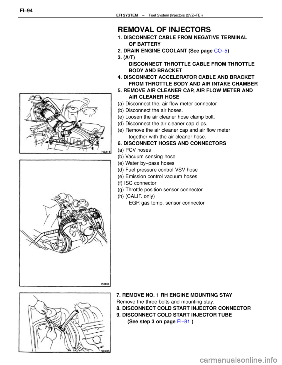
REMOVAL OF INJECTORS
1. DISCONNECT CABLE FROM NEGATIVE TERMINAL
OF BATTERY
2. DRAIN ENGINE COOLANT (See page CO±5)
3. (A/T)
DISCONNECT THROTTLE CABLE FROM THROTTLE
BODY AND BRACKET
4. DISCONNECT ACCELERATOR CABLE AND BRACKET
FROM THROTTLE BODY AND AIR INTAKE CHAMBER
5. REMOVE AIR CLEANER CAP, AIR FLOW METER AND
AIR CLEANER HOSE
(a) Disconnect the. air flow meter connector.
(b) Disconnect the air hoses.
(e) Loosen the air cleaner hose clamp bolt.
(d) Disconnect the air cleaner cap clips.
(e) Remove the air cleaner cap and air flow meter
together with the air cleaner hose.
6. DISCONNECT HOSES AND CONNECTORS
(a) PCV hoses
(b) Vacuum sensing hose
(e) Water by±pass hoses
(d) Fuel pressure control VSV hose
(e) Emission control vacuum hoses
(f) ISC connector
(g) Throttle position sensor connector
(h) (CALIF. only)
EGR gas temp. sensor connector
7. REMOVE NO. 1 RH ENGINE MOUNTING STAY
Remove the three bolts and mounting stay.
8. DISCONNECT COLD START INJECTOR CONNECTOR
9. DISCONNECT COLD START INJECTOR TUBE
(See step 3 on page FI±81 )
± EFI SYSTEMFuel System (Injectors (2VZ±FE))FI±94
Page 1114 of 2389

16. CONNECT ACCELERATOR CABLE AND BRACKET TO
THROTTLE BODY AND AIR INTAKE CHAMBER
17. (A/T)
CONNECT THROTTLE CABLE TO THROTTLE BODY
AND BRACKET, AND ADJUST IT
18. FILL WITH COOLANT (See page CO±5)
19. CONNECT CABLE TO NEGATIVE TERMINAL OF
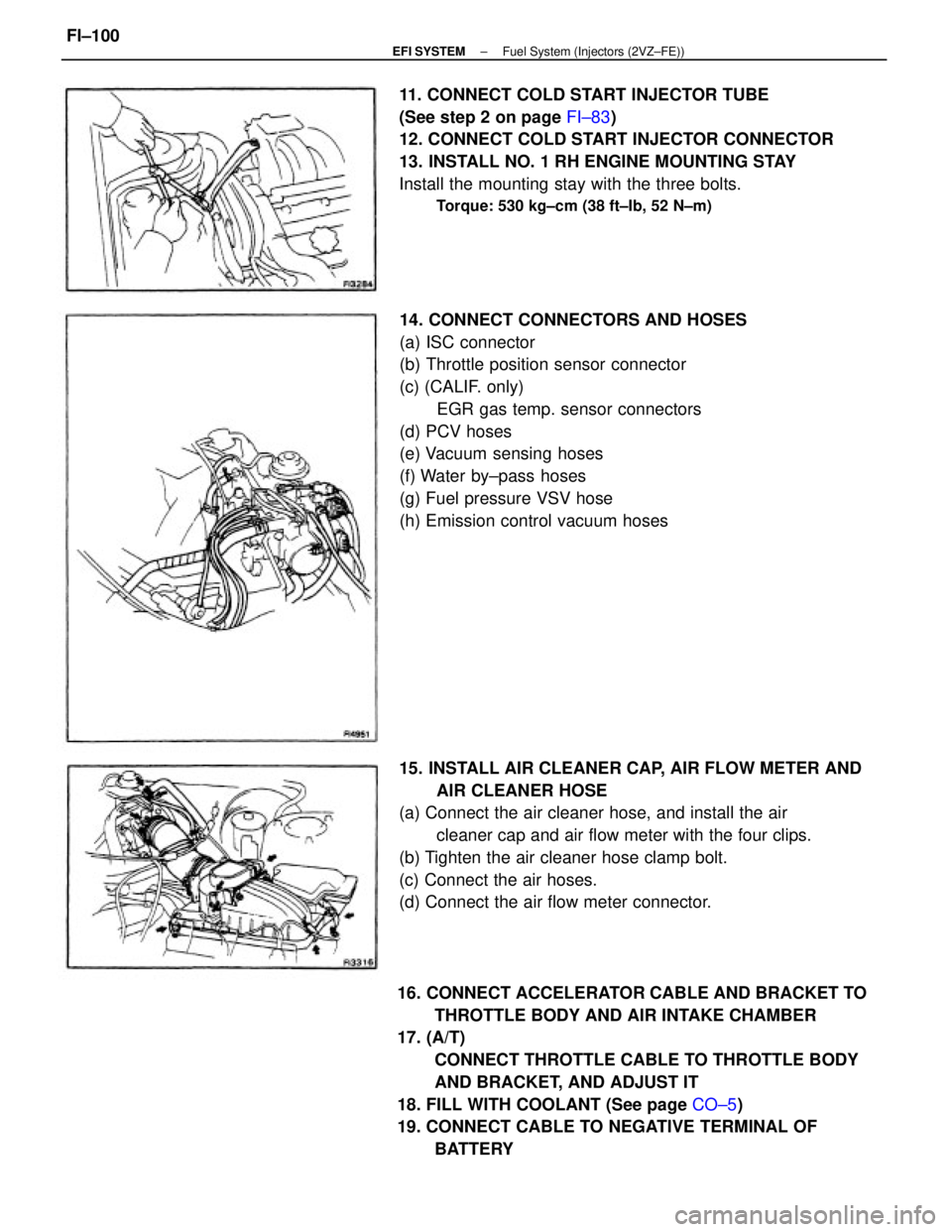
BATTERY 14. CONNECT CONNECTORS AND HOSES
(a) ISC connector
(b) Throttle position sensor connector
(c) (CALIF. only)
EGR gas temp. sensor connectors
(d) PCV hoses
(e) Vacuum sensing hoses
(f) Water by±pass hoses
(g) Fuel pressure VSV hose
(h) Emission control vacuum hoses
15. INSTALL AIR CLEANER CAP, AIR FLOW METER AND
AIR CLEANER HOSE
(a) Connect the air cleaner hose, and install the air
cleaner cap and air flow meter with the four clips.
(b) Tighten the air cleaner hose clamp bolt.
(c) Connect the air hoses.
(d) Connect the air flow meter connector. 11. CONNECT COLD START INJECTOR TUBE
(See step 2 on page FI±83)
12. CONNECT COLD START INJECTOR CONNECTOR
13. INSTALL NO. 1 RH ENGINE MOUNTING STAY
Install the mounting stay with the three bolts.
Torque: 530 kg±cm (38 ft±Ib, 52 N±m)
± EFI SYSTEMFuel System (Injectors (2VZ±FE))FI±100
Page 1121 of 2389

(d) Reconnect the sensor connector.
REMOVAL OF THROTTLE BODY
1. DRAIN ENGINE COOLANT (See page CO±4)
2. (A/T)
DISCONNECT THROTTLE CABLE FROM THROTTLE
LINKAGE
3. DISCONNECT ACCELERATOR CABLE FROM
THROTTLE LINKAGE
4. DISCONNECT AIR CLEANER HOSE
5. DISCONNECT THROTTLE POSITION SENSOR
CONNECTOR
6. DISCONNECT ISC VALVE CONNECTOR
7. REMOVE THROTTLE BODY
(a) Disconnect the following hoses:
wPCV hose
wWater by±pass hoses
wAir tube hose
wEmission control vacuum hoses
INSPECTION OF THROTTLE BODY
1. CLEAN THROTTLE BODY
(a) Using a soft brush and carburetor cleaner, clean the cast
parts.
(b) Using compressed air, clean all the passages and apertures.
NOTICE: To prevent deterioration, do not clean the throttle
position sensor.
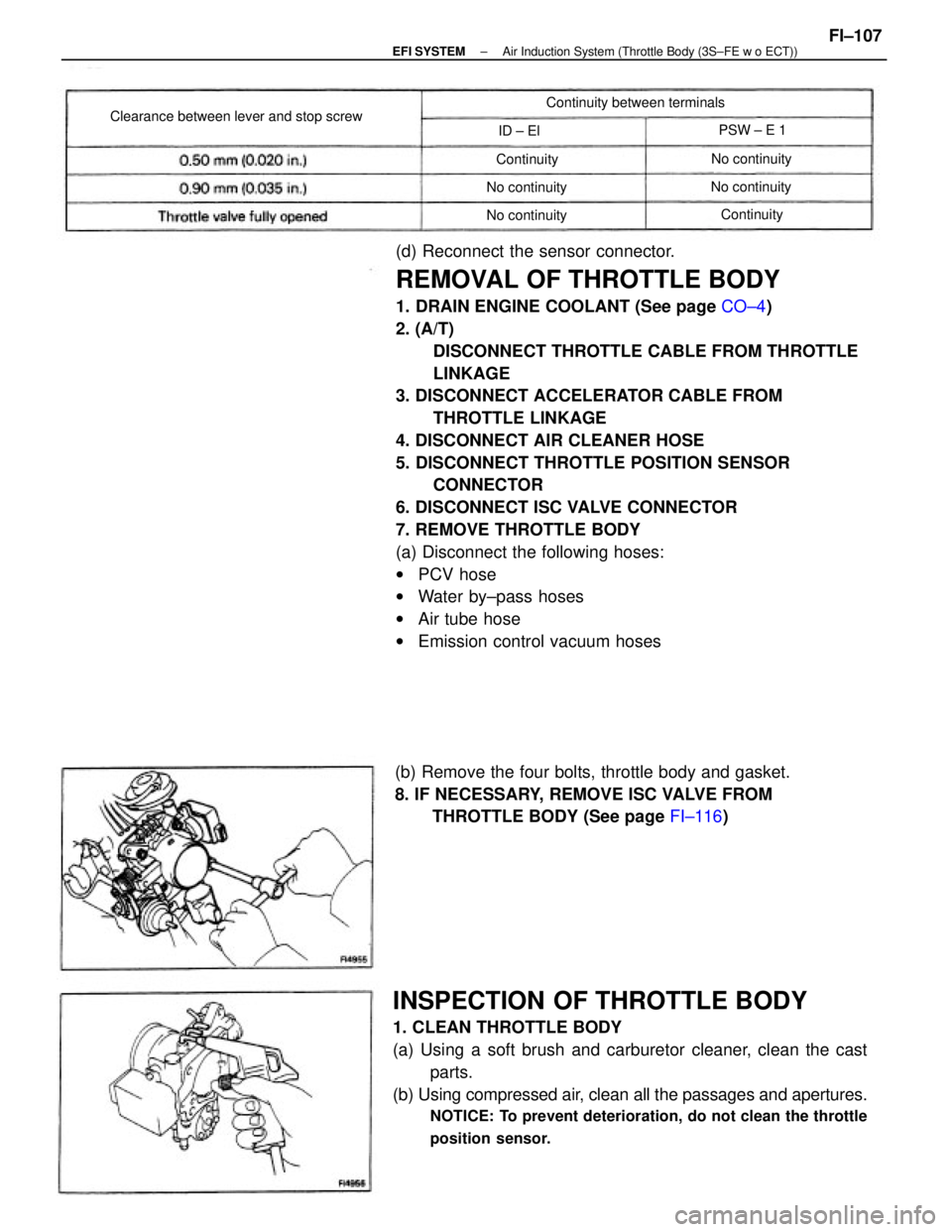
(b) Remove the four bolts, throttle body and gasket.
8. IF NECESSARY, REMOVE ISC VALVE FROM
THROTTLE BODY (See page FI±116)
Clearance between lever and stop screwContinuity between terminals
No continuity
No continuity
No continuity
No continuityPSW ± E 1
Continuity
Continuity ID ± El
± EFI SYSTEMAir Induction System (Throttle Body (3S±FE w o ECT))FI±107
Page 1123 of 2389

(b) Connect the following hoses:
wPCV hose
wWater by±pass hoses
wAir tube hose
wEmission control vacuum hoses
3. CONNECT ISC VALVE CONNECTOR
4. CONNECT THROTTLE POSITION SENSOR
CONNECTOR
5. CONNECT AIR CLEANER HOSE
6. CONNECT ACCELERATOR CABLE, AND ADJUST IT
7. (A/T)
CONNECT THROTTLE CABLE, AND ADJUST IT
8. FILL WITH ENGINE COOLANT (See page CO±5)
INSTALLATION OF THROTTLE BODY
1. INSTALL ISC VALVE TO THROTTLE BODY
(See page FI±117)
2. INSTALL THROTTLE BODY
(a) Install a new gasket and the throttle body with the four bolts.
Torque: 195 kg±cm (14 ft±Ib, 19 N±m)
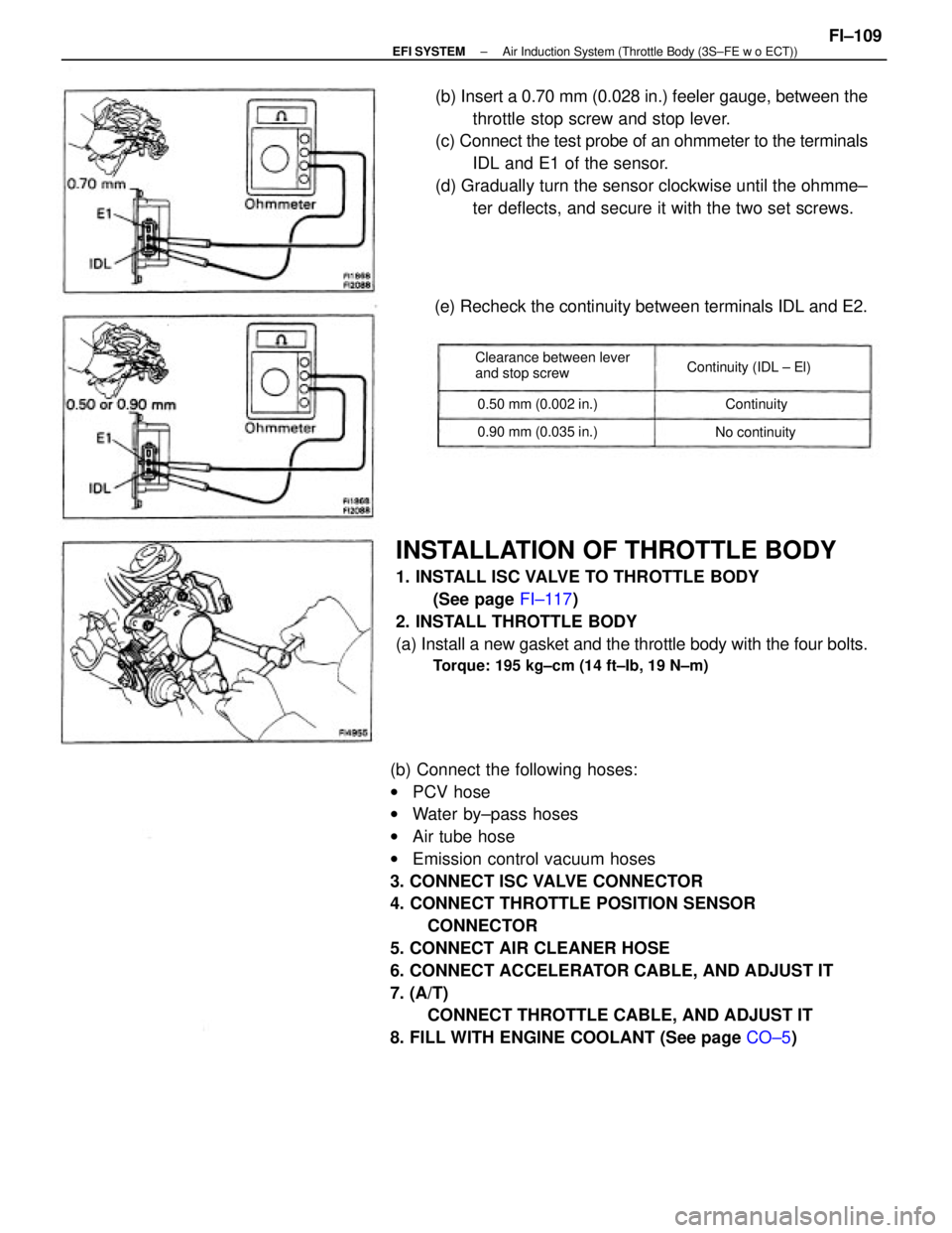
(b) Insert a 0.70 mm (0.028 in.) feeler gauge, between the
throttle stop screw and stop lever.
(c) Connect the test probe of an ohmmeter to the terminals
IDL and E1 of the sensor.
(d) Gradually turn the sensor clockwise until the ohmme±
ter deflects, and secure it with the two set screws.
(e) Recheck the continuity between terminals IDL and E2.
Clearance between lever
and stop screwContinuity (IDL ± El)
0.90 mm (0.035 in.) 0.50 mm (0.002 in.)
No continuityContinuity
± EFI SYSTEMAir Induction System (Throttle Body (3S±FE w o ECT))FI±109
Page 1127 of 2389
(d) Reconnect the sensor connector.
REMOVAL OF THROTTLE BODY
1. DRAIN ENGINE COOLANT (See page CO±5)
2. (A/T)
DISCONNECT THROTTLE CABLE FROM THROTTLE
LINKAGE
3. DISCONNECT ACCELERATOR CABLE FROM
THROTTLE LINKAGE
4. REMOVE AIR CLEANER CAP, AIR FLOW METER AND
AIR CLEANER HOSE
(a) Disconnect the air flow meter connector.
(b) Disconnect the air hoses.
(c) Loosen the air cleaner hose clamp bolt.
(d) Disconnect the air cleaner cap clips.
(e) Remove the air cleaner cap, air flow meter and air cleaner
hose assembly.
5. DISCONNECT THROTTLE POSITION SENSOR
CONNECTOR
6. REMOVE THROTTLE BODY
(a) Disconnect the following hoses:
wPCV hose
wWater by±pass hoses
wEmission control vacuum hoses
(b) (A/T)
Remove the two bolts and throttle cable bracket.
(c) Remove the four (M/T) or three (A/T) bolts, throttle body
and gasket.
Clearance between
lever and stop screwBetween
terminalsResistance
± EFI SYSTEMAir Induction System (Throttle Body (2VZ±FE))FI±113
Page 1129 of 2389
(b) (A/T)
Install the throttle cable bracket with the two bolts.
Torque: 130 kg±cm (9 ft±Ib, 13 N±m)
(c) Connect the following hoses:
wPCV hose
wWater by±pass hoses
wEmission control vacuum hoses
2. CONNECT THROTTLE POSITION SENSOR
CONNECTOR
3. INSTALL AIR CLEANER CAP, AIR FLOW METER AND
AIR CLEANER HOSE
(a) Connect the air cleaner hose, and install the air
cleaner cap and air flow meter with the four clips.
(b) Tighten the air cleaner hose clamp bolt.
(c) Connect the air hoses.
(d) Connect the air flow meter connector.
INSTALLATION OF THROTTLE BODY
1. INSTALL THROTTLE BODY
(a) Install a new gasket and the throttle body with the four
(M/T) or three (A/n bolts.
Torque: 130 kg±cm (9 ft±Ib, 13 N±m)
4. CONNECT ACCELERATOR CABLE, AND ADJUST IT
5. (A/T)
CONNECT THROTTLE CABLE, AND ADJUST IT
6. FILL WITH ENGINE COOLANT (See page CO±5)
± EFI SYSTEMAir Induction System (Throttle Body (2VZ±FE))FI±115