Page 1132 of 2389
2. INSPECT ISC VALVE RESISTANCE
(a) Disconnect the ISC valve connector.
(b) Using an ohmmeter, measure the resistance between ter-
minal 131 ± S1 or S3, and B2 ± S2 or S4.
Resistance: B1 ± S1 or S3 10 ± 30
�
B2 ± S2 or S4 10 ± 30 �
If the resistance is not as specified, replace the ISC valve.
(c) Reconnect the ISC valve connector.
REMOVAL OF ISC VALVE
1. DRAIN ENGINE COOLANT (See page CO±5)
2. DISCONNECT ISC VALVE CONNECTOR
3. DISCONNECT AIR HOSE AND TWO WATER BY±PASS
HOSES
ON±VEHICLE INSPECTION
1. CHECK FOR OPERATING SOUND FROM ISC VALVE
Check that there is a clicking sound immediately stopping
the engine.
Idle Speed Control (ISC) Valve
(2VZ±FE)
± EFI SYSTEMAir Induction System (Idle Speed Control (ISC) Valve (2VZ±FE))FI±118
Page 1133 of 2389
INSTALLATION OF ISC VALVE
1. INSTALL ISC VALVE
(a) Install a new gasket and the ISC valve with the two bolts.
Torque: 130 kg±cm (9 ft±Ib, 13 N±m)
(b) Connect the wire harness clamp with the nut.
INSPECTION OF ISC VALVE
INSPECT ISC VALVE OPERATION
(a) Apply battery voltage to terminals 81 and B2, and while re-
peatedly grounding S1 ± S2 ± S3 ± S4 ±
S1 in sequence, check that the valve moves to¿¿rd the
closed position.
2. CONNECT TWO WATER BY±PASS HOSES AND AIR
HOSE
3. CONNECT ISC VALVE CONNECTOR
4. FILL WITH ENGINE COOLANT (See page CO±5) (b) Apply battery voltage to terminals 81 and 82, and while
repeatedly grounding S4 ± S3 S2 ± S 1 ±
S4 in sequence, check that the valve moves toward
the open position.
If operation is not as specified, replace the ISC valve. 4. REMOVE ISC VALVE
(a) Remove the nut, and disconnect the wire harness clamp.
(b) Remove the two bolts, ISC valve and gasket.
± EFI SYSTEMAir Induction System (Idle Speed Control (ISC) Valve(2VZ FE))
FI±119
Page 1148 of 2389
Voltage at ECU Wiring Connectors (3S±FE)
No trouble (ºCHECKº engine warning light off) and engine running
Stop light SW 4N (Brake pedal depressed) or defogger SW ONCheck connector TE1 ± E1 not connected
Check connector TE 1 ± E 1 connectedMeasuring plate fully closed
Ex. shift position P or N rangeIntake air temp. 20°C (68°F)
Coolant temp. 80°C (1 760F) Measuring plate fully open
Shift position P or N rangeThrottle valve fully closedThrottle valve fully closed
Heater blower SW ON Air conditioning ONThrottle valve open
Throttle valve open
Throttle valve open
Cranking or idlingIG SW ONSTD voltage (V) Condition
3,000 rpm
IG SW ONIG SW ON1G SW ON
IG SW ON Terminals
IG SW ON
CrankingIdling
± EFI SYSTEMElectronic Control System (Electronic Controlled Unit(ECU))
FI±133
Page 1149 of 2389
Voltage at ECU Wiring Connectors (2VZ±FE)
No trouble (ºCHECKº engine warning light off) and engine running
Stop light SW ON (Brake pedal depressed)Check connector TE1 ± E1 not connected
Check connector TE1 ± E1 connected
Ex. shift position P or N range Measuring plate fully closed
Intake air temp. 20°C (68°F)
Coolant temp. 80°C (176°F) Measuring plate fully open
Shift position P or N range Throttle valve fully closed
Heater blower SW ON Air conditioning ON Throttle valve open Throttle valve open
Cranking or idlingSm voltage (V)
3,000 rpm IG SW ON
IG SW ON
IG SW ON
IG SW ON
IG SW ON 1G SW ON Terminals
Cranking Idling
± EFI SYSTEMElectronic Control System (Electronic Controlled Unit(ECU))
FI±134
Page 1150 of 2389
2. INSPECT RESISTANCE OF ECU
NOTICE:
wDo not touch the ECU terminals.
wThe tester probe should be inserted into the wiring
connector from the wiring side.
Check the resistance between each terminal of the wiring
connectors.
wDisconnect the connectors from the ECU.
wMeasure the resistance at each terminal.
Resistance of ECU Wiring Connectors (3S±FE)
Measuring plate fully closed
Intake air temp. 20
°C (68°F)
Coolant temp. 80°C (176°F)
Measuring plate fully openThrottle valve fully closed
Throttle valve fully closedThrottle valve fully closed
Throttle valve fully closedThrottle valve fully open
Throttle valve fully openThrottle valve open
STD resistance (�)
Throttle valve open
Condition Terminals
± EFI SYSTEMElectronic Control System (Electronic Controlled Unit
(ECU))FI±135
Page 1151 of 2389
Resistance of ECU Wiring Connectors (2VZ±FE)
Coolant temp. 80°C (176°F)
Measuring plate fully closed
Intake air temp. 20°C (68°F)
Measuring plate fully open
Throttle valve fully closed
Throttle valve fully closed Throttle valve fully openSTD resistance (
��
Throttle valve open TerminalsCondition
± EFI SYSTEMElectronic Control System (Electronic Controlled Unit(ECU))
FI±136
Page 1157 of 2389

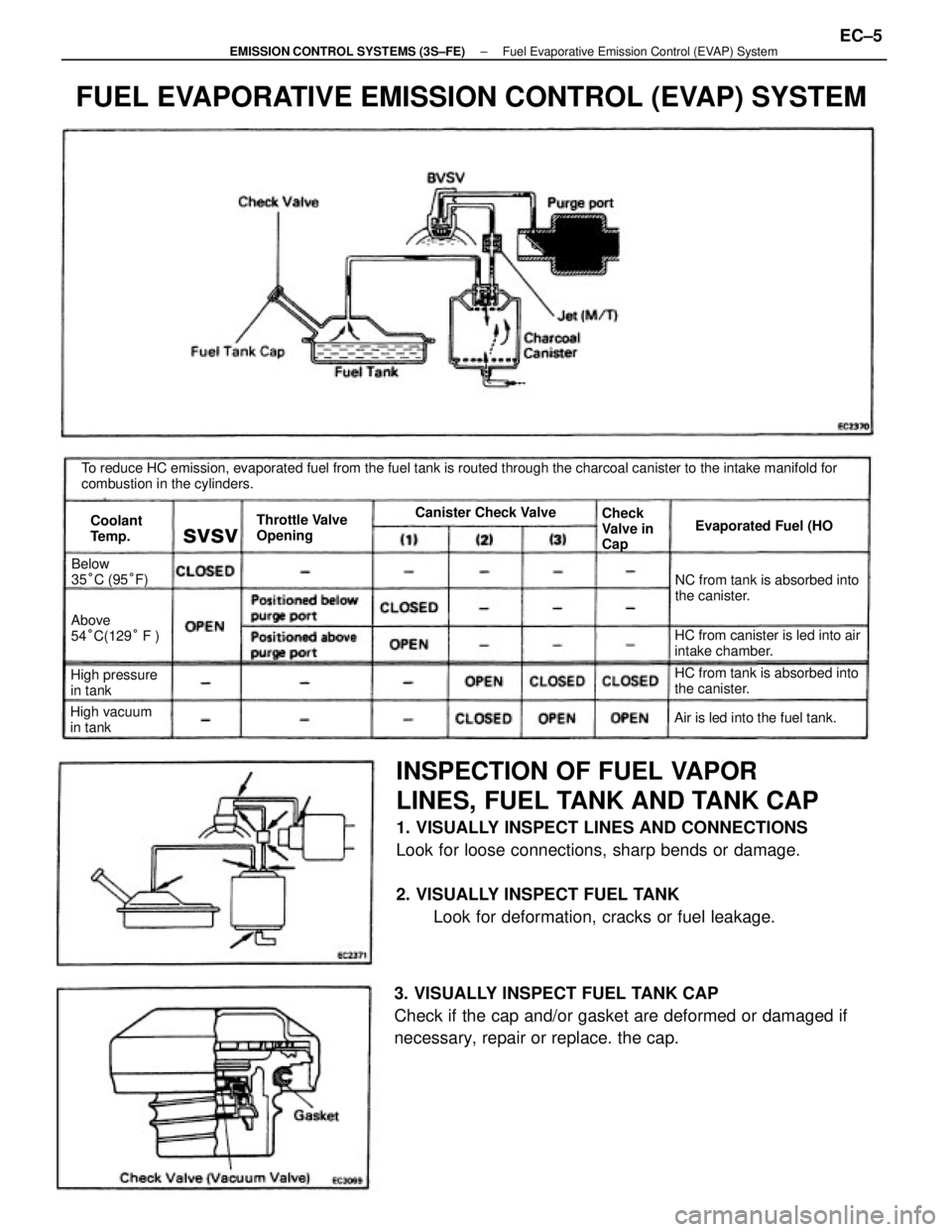
INSPECTION OF FUEL VAPOR
LINES, FUEL TANK AND TANK CAP
1. VISUALLY INSPECT LINES AND CONNECTIONS
Look for loose connections, sharp bends or damage.
2. VISUALLY INSPECT FUEL TANK
Look for deformation, cracks or fuel leakage.
3. VISUALLY INSPECT FUEL TANK CAP
Check if the cap and/or gasket are deformed or damaged if
necessary, repair or replace. the cap.
To reduce HC emission, evaporated fuel from the fuel tank is routed through the charcoal canister to the intake manifold for
combustion in the cylinders.
FUEL EVAPORATIVE EMISSION CONTROL (EVAP) SYSTEM
HC from canister is led into air
intake chamber.NC from tank is absorbed into
the canister.
HC from tank is absorbed into
the canister.
Air is led into the fuel tank. Throttle Valve
OpeningEvaporated Fuel (HO
High pressure
in tankAbove
54°C(129° F )
High vacuum
in tankBelow
35°C (95°F)Canister Check Valve
Check
Valve in
Cap Coolant
Temp.
svsv
± EMISSION CONTROL SYSTEMS (3S±FE)Fuel Evaporative Emission Control (EVAP) SystemEC±5
Page 1158 of 2389

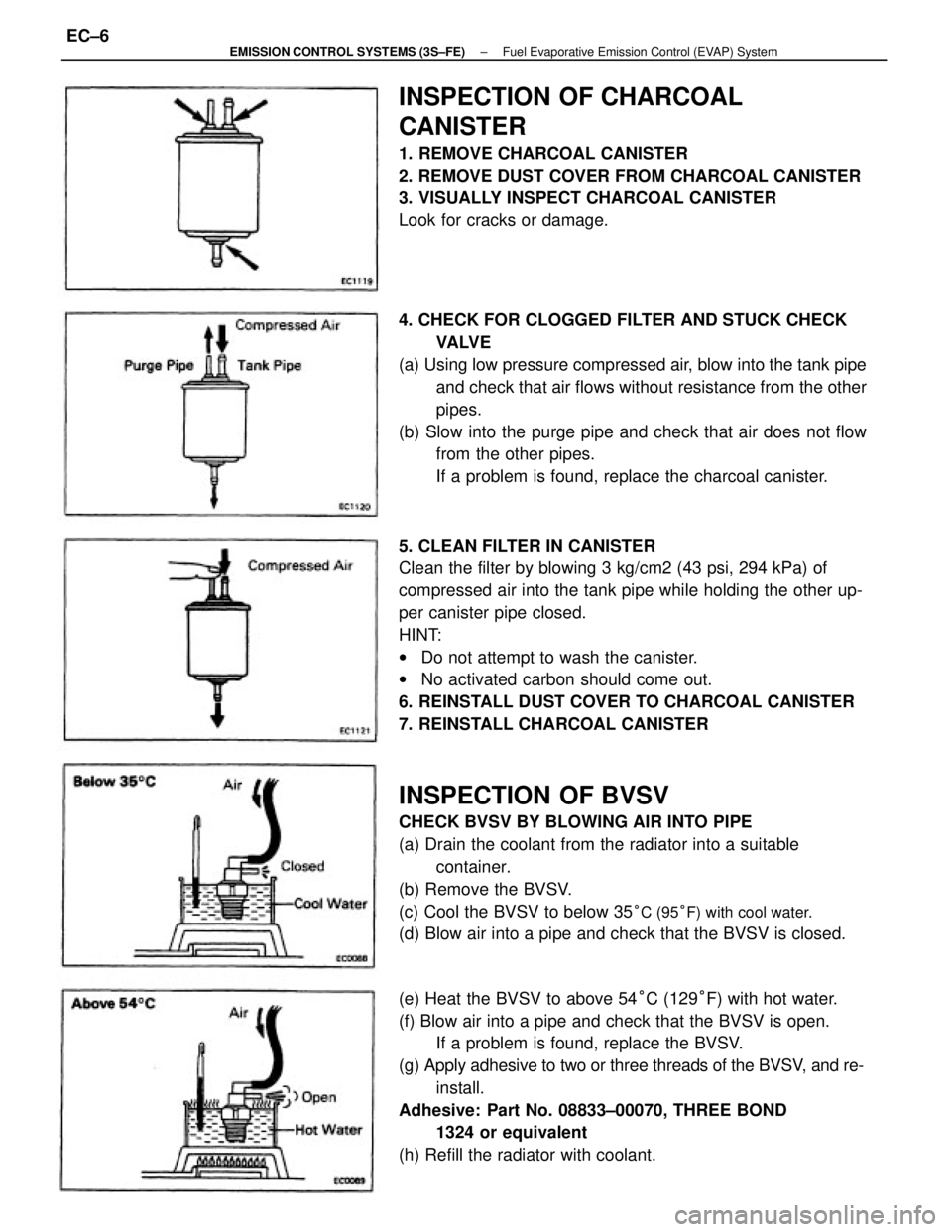
5. CLEAN FILTER IN CANISTER
Clean the filter by blowing 3 kg/cm2 (43 psi, 294 kPa) of
compressed air into the tank pipe while holding the other up-
per canister pipe closed.
HINT:
wDo not attempt to wash the canister.
wNo activated carbon should come out.
6. REINSTALL DUST COVER TO CHARCOAL CANISTER
7. REINSTALL CHARCOAL CANISTER
INSPECTION OF BVSV
CHECK BVSV BY BLOWING AIR INTO PIPE
(a) Drain the coolant from the radiator into a suitable
container.
(b) Remove the BVSV.
(c) Cool the BVSV to below 35
°C (95°F) with cool water.
(d) Blow air into a pipe and check that the BVSV is closed. 4. CHECK FOR CLOGGED FILTER AND STUCK CHECK
VA LV E
(a) Using low pressure compressed air, blow into the tank pipe
and check that air flows without resistance from the other
pipes.
(b) Slow into the purge pipe and check that air does not flow
from the other pipes.
If a problem is found, replace the charcoal canister.
(e) Heat the BVSV to above 54°C (129°F) with hot water.
(f) Blow air into a pipe and check that the BVSV is open.
If a problem is found, replace the BVSV.
(g) Apply adhesive to two or three threads of the BVSV, and re-
install.
Adhesive: Part No. 08833±00070, THREE BOND
1324 or equivalent
(h) Refill the radiator with coolant.
INSPECTION OF CHARCOAL
CANISTER
1. REMOVE CHARCOAL CANISTER
2. REMOVE DUST COVER FROM CHARCOAL CANISTER
3. VISUALLY INSPECT CHARCOAL CANISTER
Look for cracks or damage.
± EMISSION CONTROL SYSTEMS (3S±FE)Fuel Evaporative Emission Control (EVAP) SystemEC±6