1986 TOYOTA CAMRY V20 coolant
[x] Cancel search: coolantPage 1161 of 2389
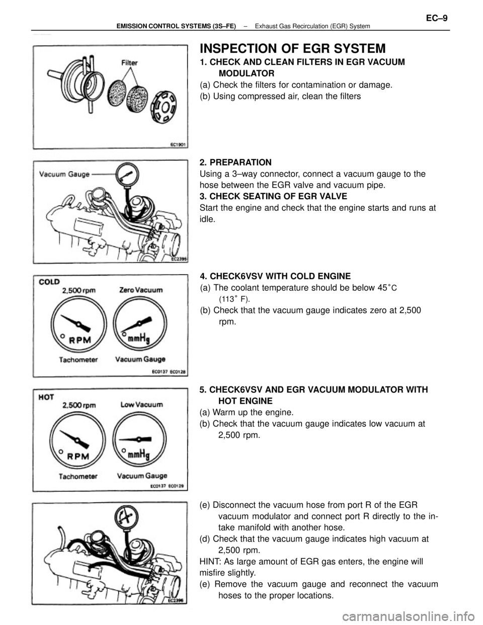
(e) Disconnect the vacuum hose from port R of the EGR
vacuum modulator and connect port R directly to the in-
take manifold with another hose.
(d) Check that the vacuum gauge indicates high vacuum at
2,500 rpm.
HINT: As large amount of EGR gas enters, the engine will
misfire slightly.
(e) Remove the vacuum gauge and reconnect the vacuum
hoses to the proper locations. 2. PREPARATION
Using a 3±way connector, connect a vacuum gauge to the
hose between the EGR valve and vacuum pipe.
3. CHECK SEATING OF EGR VALVE
Start the engine and check that the engine starts and runs at
idle.
5. CHECK6VSV AND EGR VACUUM MODULATOR WITH
HOT ENGINE
(a) Warm up the engine.
(b) Check that the vacuum gauge indicates low vacuum at
2,500 rpm.
INSPECTION OF EGR SYSTEM
1. CHECK AND CLEAN FILTERS IN EGR VACUUM
MODULATOR
(a) Check the filters for contamination or damage.
(b) Using compressed air, clean the filters
4. CHECK6VSV WITH COLD ENGINE
(a) The coolant temperature should be below 45
°C
(113° F).
(b) Check that the vacuum gauge indicates zero at 2,500
rpm.
± EMISSION CONTROL SYSTEMS (3S±FE)Exhaust Gas Recirculation (EGR) SystemEC±9
Page 1162 of 2389
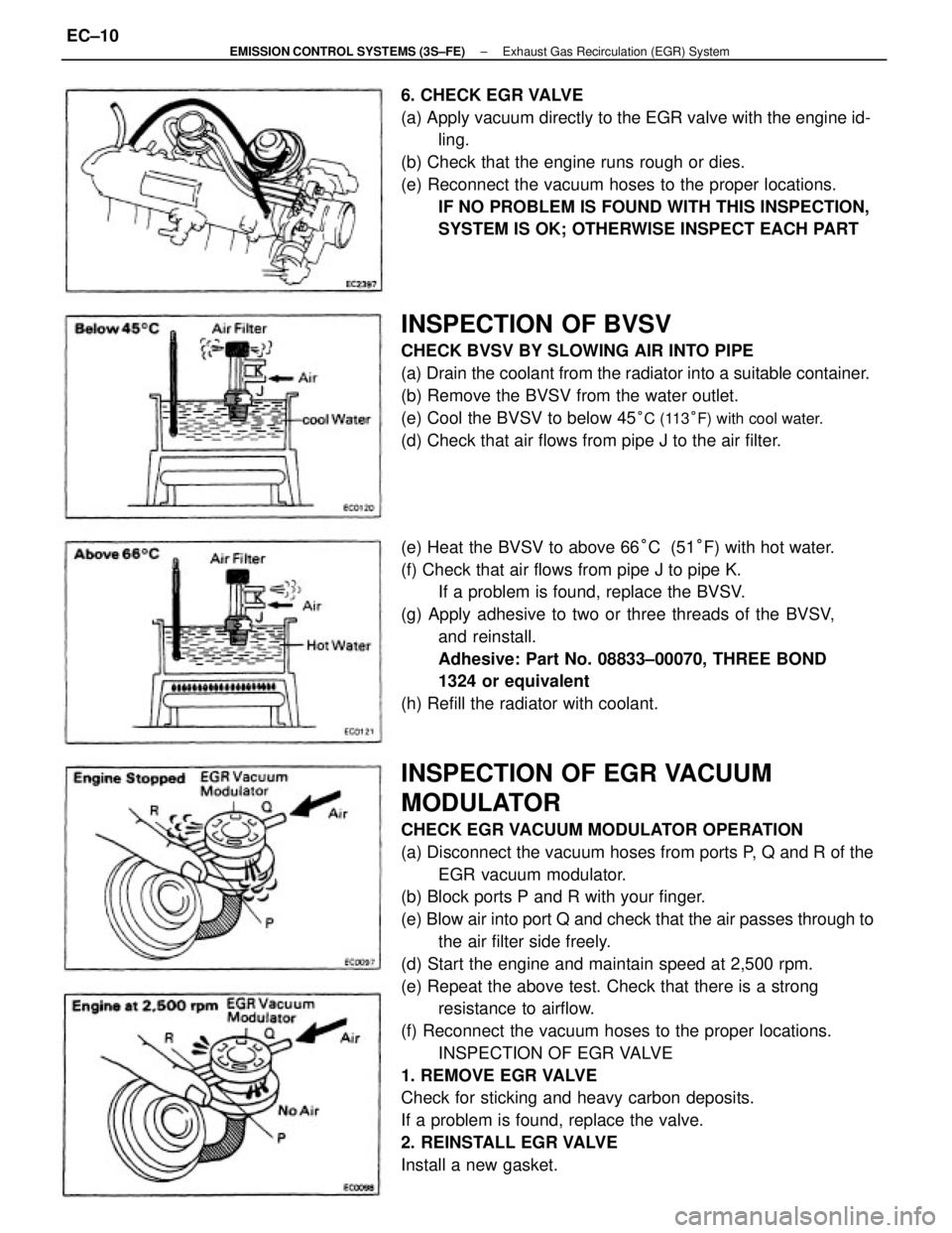
INSPECTION OF EGR VACUUM
MODULATOR
CHECK EGR VACUUM MODULATOR OPERATION
(a) Disconnect the vacuum hoses from ports P, Q and R of the
EGR vacuum modulator.
(b) Block ports P and R with your finger.
(e) Blow air into port Q and check that the air passes through to
the air filter side freely.
(d) Start the engine and maintain speed at 2,500 rpm.
(e) Repeat the above test. Check that there is a strong
resistance to airflow.
(f) Reconnect the vacuum hoses to the proper locations.
INSPECTION OF EGR VALVE
1. REMOVE EGR VALVE
Check for sticking and heavy carbon deposits.
If a problem is found, replace the valve.
2. REINSTALL EGR VALVE
Install a new gasket.
INSPECTION OF BVSV
CHECK BVSV BY SLOWING AIR INTO PIPE
(a) Drain the coolant from the radiator into a suitable container.
(b) Remove the BVSV from the water outlet.
(e) Cool the BVSV to below 45
°C (113°F) with cool water.
(d) Check that air flows from pipe J to the air filter.
(e) Heat the BVSV to above 66°C (51°F) with hot water.
(f) Check that air flows from pipe J to pipe K.
If a problem is found, replace the BVSV.
(g) Apply adhesive to two or three threads of the BVSV,
and reinstall.
Adhesive: Part No. 08833±00070, THREE BOND
1324 or equivalent
(h) Refill the radiator with coolant. 6. CHECK EGR VALVE
(a) Apply vacuum directly to the EGR valve with the engine id-
ling.
(b) Check that the engine runs rough or dies.
(e) Reconnect the vacuum hoses to the proper locations.
IF NO PROBLEM IS FOUND WITH THIS INSPECTION,
SYSTEM IS OK; OTHERWISE INSPECT EACH PART
± EMISSION CONTROL SYSTEMS (3S±FE)Exhaust Gas Recirculation (EGR) SystemEC±10
Page 1169 of 2389
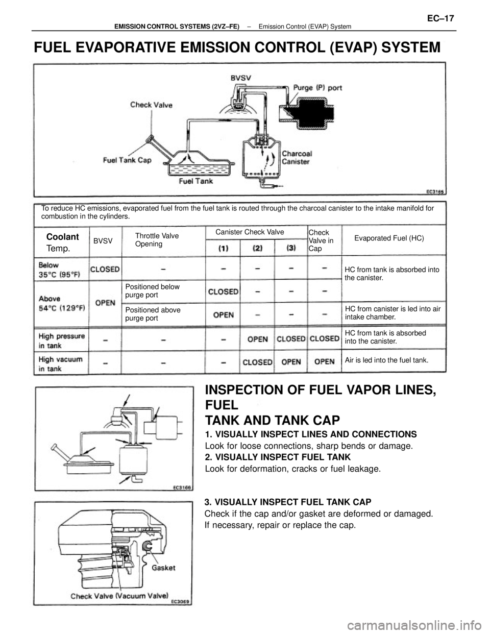
INSPECTION OF FUEL VAPOR LINES,
FUEL
TANK AND TANK CAP
1. VISUALLY INSPECT LINES AND CONNECTIONS
Look for loose connections, sharp bends or damage.
2. VISUALLY INSPECT FUEL TANK
Look for deformation, cracks or fuel leakage.
To reduce HC emissions, evaporated fuel from the fuel tank is routed through the charcoal canister to the intake manifold for
combustion in the cylinders.
3. VISUALLY INSPECT FUEL TANK CAP
Check if the cap and/or gasket are deformed or damaged.
If necessary, repair or replace the cap.
FUEL EVAPORATIVE EMISSION CONTROL (EVAP) SYSTEM
HC from canister is led into air
intake chamber. HC from tank is absorbed into
the canister.
HC from tank is absorbed
into the canister. Positioned below
purge port
Positioned above
purge port
Air is led into the fuel tank. Throttle Valve
OpeningEvaporated Fuel (HC) Canister Check Valve
Check
Valve in
Cap
Coolant
Te m p .BVSV
± EMISSION CONTROL SYSTEMS (2VZ±FE)Emission Control (EVAP) SystemEC±17
Page 1170 of 2389
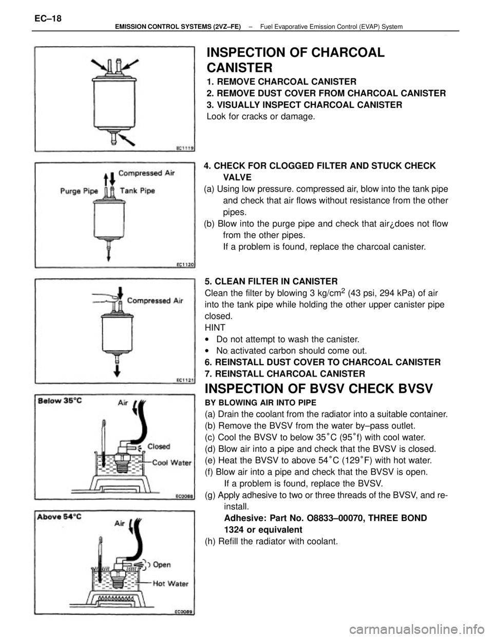
5. CLEAN FILTER IN CANISTER
Clean the filter by blowing 3 kg/cm
2 (43 psi, 294 kPa) of air
into the tank pipe while holding the other upper canister pipe
closed.
HINT
wDo not attempt to wash the canister.
wNo activated carbon should come out.
6. REINSTALL DUST COVER TO CHARCOAL CANISTER
7. REINSTALL CHARCOAL CANISTER
INSPECTION OF BVSV CHECK BVSV
BY BLOWING AIR INTO PIPE
(a) Drain the coolant from the radiator into a suitable container.
(b) Remove the BVSV from the water by±pass outlet.
(c) Cool the BVSV to below 35°C (95°f) with cool water.
(d) Blow air into a pipe and check that the BVSV is closed.
(e) Heat the BVSV to above 54°C (129°F) with hot water.
(f) Blow air into a pipe and check that the BVSV is open.
If a problem is found, replace the BVSV.
(g) Apply adhesive to two or three threads of the BVSV, and re-
install.
Adhesive: Part No. O8833±00070, THREE BOND
1324 or equivalent
(h) Refill the radiator with coolant.
INSPECTION OF CHARCOAL
CANISTER
1. REMOVE CHARCOAL CANISTER
2. REMOVE DUST COVER FROM CHARCOAL CANISTER
3. VISUALLY INSPECT CHARCOAL CANISTER
Look for cracks or damage.
4. CHECK FOR CLOGGED FILTER AND STUCK CHECK
VA LV E
(a) Using low pressure. compressed air, blow into the tank pipe
and check that air flows without resistance from the other
pipes.
(b) Blow into the purge pipe and check that air¿does not flow
from the other pipes.
If a problem is found, replace the charcoal canister.
± EMISSION CONTROL SYSTEMS (2VZ±FE)Fuel Evaporative Emission Control (EVAP) SystemEC±18
Page 1174 of 2389
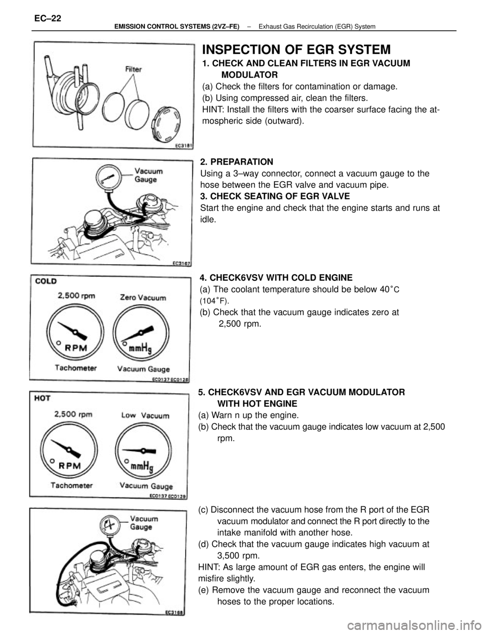
(c) Disconnect the vacuum hose from the R port of the EGR
vacuum modulator and connect the R port directly to the
intake manifold with another hose.
(d) Check that the vacuum gauge indicates high vacuum at
3,500 rpm.
HINT: As large amount of EGR gas enters, the engine will
misfire slightly.
(e) Remove the vacuum gauge and reconnect the vacuum
hoses to the proper locations.
INSPECTION OF EGR SYSTEM
1. CHECK AND CLEAN FILTERS IN EGR VACUUM
MODULATOR
(a) Check the filters for contamination or damage.
(b) Using compressed air, clean the filters.
HINT: Install the filters with the coarser surface facing the at-
mospheric side (outward).
2. PREPARATION
Using a 3±way connector, connect a vacuum gauge to the
hose between the EGR valve and vacuum pipe.
3. CHECK SEATING OF EGR VALVE
Start the engine and check that the engine starts and runs at
idle.
4. CHECK6VSV WITH COLD ENGINE
(a) The coolant temperature should be below 40
°C
(104°F).
(b) Check that the vacuum gauge indicates zero at
2,500 rpm.
5. CHECK6VSV AND EGR VACUUM MODULATOR
WITH HOT ENGINE
(a) Warn n up the engine.
(b) Check that the vacuum gauge indicates low vacuum at 2,500
rpm.
± EMISSION CONTROL SYSTEMS (2VZ±FE)Exhaust Gas Recirculation (EGR) SystemEC±22
Page 1175 of 2389
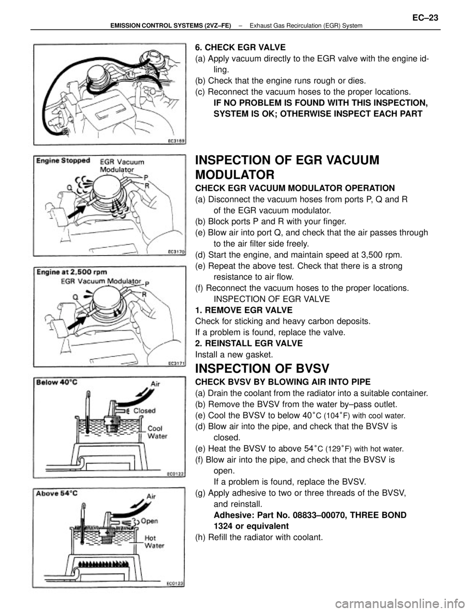
INSPECTION OF EGR VACUUM
MODULATOR
CHECK EGR VACUUM MODULATOR OPERATION
(a) Disconnect the vacuum hoses from ports P, Q and R
of the EGR vacuum modulator.
(b) Block ports P and R with your finger.
(e) Blow air into port Q, and check that the air passes through
to the air filter side freely.
(d) Start the engine, and maintain speed at 3,500 rpm.
(e) Repeat the above test. Check that there is a strong
resistance to air flow.
(f) Reconnect the vacuum hoses to the proper locations.
INSPECTION OF EGR VALVE
1. REMOVE EGR VALVE
Check for sticking and heavy carbon deposits.
If a problem is found, replace the valve.
2. REINSTALL EGR VALVE
Install a new gasket.
INSPECTION OF BVSV
CHECK BVSV BY BLOWING AIR INTO PIPE
(a) Drain the coolant from the radiator into a suitable container.
(b) Remove the BVSV from the water by±pass outlet.
(e) Cool the BVSV to below 40
°C (104°F) with cool water.
(d) Blow air into the pipe, and check that the BVSV is
closed.
(e) Heat the BVSV to above 54
°C (129°F) with hot water.
(f) Blow air into the pipe, and check that the BVSV is
open.
If a problem is found, replace the BVSV.
(g) Apply adhesive to two or three threads of the BVSV,
and reinstall.
Adhesive: Part No. 08833±00070, THREE BOND
1324 or equivalent
(h) Refill the radiator with coolant. 6. CHECK EGR VALVE
(a) Apply vacuum directly to the EGR valve with the engine id-
ling.
(b) Check that the engine runs rough or dies.
(c) Reconnect the vacuum hoses to the proper locations.
IF NO PROBLEM IS FOUND WITH THIS INSPECTION,
SYSTEM IS OK; OTHERWISE INSPECT EACH PART
± EMISSION CONTROL SYSTEMS (2VZ±FE)Exhaust Gas Recirculation (EGR) SystemEC±23
Page 1180 of 2389
The 3S±FE engine is an in±line 4±cylinder engine with the cylinders numbered 1 ± 2 ± 3 ± 4 from the
front.
The crankshaft is supported by 5 bearing inside the crankcase. These bearing are made of aluminum
alloy.
The crankshaft is integrated with 8 weights for balance. Oil holes are placed in the center of the crank-
shaft to supply oil to the connecting rods, bearing, pistons and other components.
This engine's ignition order is 1 ± 3 ± 4 ± 2. The cylinder head is made of aluminum alloy, with a cross
flow type intake and exhaust layout and with pent±roof type combustion chambers. The spark plugs are
located in the center of the combustion chamber.
The intake manifold has 8 independent long ports and utilizes the inertial supercharging effect to im-
prove engine torque at low and medium speeds.
Exhaust and intake valves are equipped with irregular pitch springs made of special valve spring carbon
steel which are capable of functioning no matter what the engine speed.
The intake side camshaft is driven by a timing belt, and a gear on the intake side camshaft engages with
a gear on the exhaust side camshaft to drive it. The cam journal is supported at 5 places between the
valve lifters of each cylinder and on the front end of the cylinder head. Lubrication of the cam journal and
gear is accomplished by oil being supplied through the oiler port in the center of the camshaft.
Adjustment of the valve clearance is done by means of outer shim type system, in which valve adjusting
shims are located above the valve lifters. This permits replacement of the shims without removal of the
camshafts.
The resin timing belt cover is made of 2 pieces. A service hole is provided in the No. 1 belt cover for ad-
justing the timing belt tension.
Piston are made of high temperature±resistant aluminum alloy, and a depression is built into the piston
head to prevent interference with the valves.
Piston pins are the semi±floating type, with the pins fastened to the connecting rods by pressure fitting,
allowing the pistons and pins to float.
The No. 1 compression ring is made of steel and the No. 2 compression ring is made of cast iron. The oil
ring is made of a combination of steel and stainless steel. The outer diameter of each piston ring is
slightly larger than the diameter of the piston and the flexibility of the rings allows them to hug the cylin-
der walls when they are mounted on the piston rings No. 1 and No. 2 work to prevent gas leakage from
the cylinder and oil ring works to clear oil off the cylinder walls to prevent it from entering the combustion
chambers.
The cylinder block is made of cast iron. It has 4 cylinders which are approximately 2 times the length of
the piston stroke. The top of the cylinders is closed off by the cylinder head and the lower end of the cyl-
inders becomes the crankcase, in which the crankshaft is installed. In .addition, the cylinder block con-
tains a water jacket, through which coolant is pumped to cool the cylinders.
The oil pan is bolted onto the bottom of the cylinder block. The oil pan is an oil reservoir made of
pressed steel shoot. A dividing plate is included inside the oil pan to keep sufficient oil in the bottom of
the pan even when the vehicle is tilted. This dividing plate also prevents the oil from making waves when
the vehicle is topped suddenly and thus shifting the oil away from the oil pump suction pipe.
± ENGINE MECHANICALDescription (3S±FE)EM±3
Page 1182 of 2389
The 2VZ±FE engine has 6 cylinder in a V arrangement at bank of 60°. From the front of the RH bank cylin-
ders are numbered 1 ± 3 ± 5, and from the front of the LH bank cylinders are numbered 2 ± 4 ±r 6. The crankshaft is
supported by 4 bearings inside the crankcase. These bearing are made of copper and lead alloy.
The crankshaft is integrated with 5 weights for balance. Oil holes are placed in the center of the crankshaft for sup-
plying oil to the connecting rods, pistons and other components.
This engine's ignition order is 1 ± 2 ± 3 ± 4 ± 5 ± 6. The cylinder head is made of aluminum alloy, with a cross flow
type intake and exhaust layout and with pent±roof type combustion chambers. The spark plugs are located in the
center of the combustion chambers.
At,the front and rear of the intake port of the intake manifold, a water passage has been provided which connects
the RH and LH cylinder heads.
Exhaust and intake valves are equipped with irregular pitch springs made of special valve spring carbon steel which
are capable of functioning no matter what the engine speed.
The RH and LH intake camshaft are driven by a single timing belt, and a gear on the intake side camshaft engages
with a gear on the exhaust side camshaft to drive it. The cam journal is supported at 5 (intake) or 4
(exhaust) places between the valve liters of each cylinder and on the front end of the cylinder head. Lubrication of
the cam journals and gears is accomplished by oil being supplied through the oiler port in the center of the camshaft.
Adjustment of the valve clearance is done by means of outer shim type system, in which valve adjusting shims are
located above the valve lifters. The permits replacement of the shims without removal of the camshafts.
The timing belt cover is composed of resin type No. 2 and No. 1 above and below the RH mounting bracket.
Piston are made high temperature±resistant aluminum alloy, and a depression is built into the piston head to prevent
interference with the valves.
Piston pins are the semi±floating type, with the pins fastened to the connecting rods by pressure fitting, allowing the
pistons and pins to float.
The No. 1 compression ring is made of steel and the No. 2 compression ring is made±of cast iron. The oil ring is
made of a combination of steel and stainless steel. The outer diameter of each piston ring is slightly larger than the
diameter of the piston and the flexibility of the rings allows them to hug the cylinder walls when they are mounted on
the piston. Compression rings No. 1 and No. 2 work to prevent gas leakage from the cylinder and oil ring works to
clear oil off the cylinder walls to prevent it from entering the combustion chambers.
The cylinder block is made of cast iron with a bank angle of 60°. It has 6 cylinders which are approximately 2
times the length of the piston stroke. The top of the cylinders is closed off by the cylinder heads and the lower end of
the cylinders becomes the crankcase, in which the crankshaft is installed. In addition, the cylinder block contains a
water jacket, through which coolant is pumped to cool the cylinders.
The oil pan is bolted onto the bottom of the cylinder block. The oil pan is an oil reservoir made of pressed steel
sheet. A dividing plate is included inside the oil pan to keep sufficient oil in the bottom of the pan even when the ve-
hicle is tilted. This dividing plate also prevents the oil from making waves when the vehicle is stopped suddenly and
thus shifting the oil away from the oil pump suction pipe.
± ENGINE MECHANICALDescription (2VZ±FE)EM±5