Page 1009 of 2389
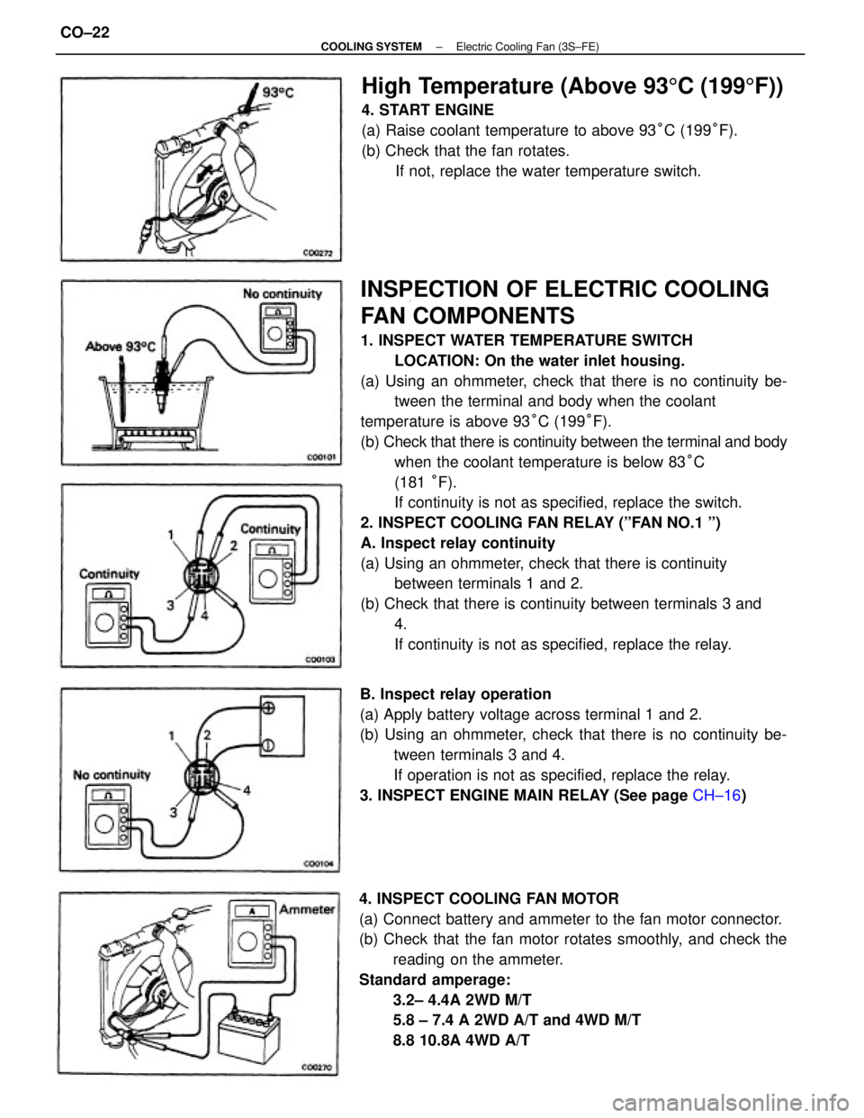
INSPECTION OF ELECTRIC COOLING
FAN COMPONENTS
1. INSPECT WATER TEMPERATURE SWITCH
LOCATION: On the water inlet housing.
(a) Using an ohmmeter, check that there is no continuity be-
tween the terminal and body when the coolant
temperature is above 93°C (199°F).
(b) Check that there is continuity between the terminal and body
when the coolant temperature is below 83°C
(181 °F).
If continuity is not as specified, replace the switch.
2. INSPECT COOLING FAN RELAY (ºFAN NO.1 º)
A. Inspect relay continuity
(a) Using an ohmmeter, check that there is continuity
between terminals 1 and 2.
(b) Check that there is continuity between terminals 3 and
4.
If continuity is not as specified, replace the relay.
4. INSPECT COOLING FAN MOTOR
(a) Connect battery and ammeter to the fan motor connector.
(b) Check that the fan motor rotates smoothly, and check the
reading on the ammeter.
Standard amperage:
3.2± 4.4A 2WD M/T
5.8 ± 7.4 A 2WD A/T and 4WD M/T
8.8 10.8A 4WD A/T B. Inspect relay operation
(a) Apply battery voltage across terminal 1 and 2.
(b) Using an ohmmeter, check that there is no continuity be-
tween terminals 3 and 4.
If operation is not as specified, replace the relay.
3. INSPECT ENGINE MAIN RELAY (See page CH±16)
High Temperature (Above 935C (1995F))
4. START ENGINE
(a) Raise coolant temperature to above 93°C (199°F).
(b) Check that the fan rotates.
If not, replace the water temperature switch.
± COOLING SYSTEMElectric Cooling Fan (3S±FE)CO±22
Page 1011 of 2389
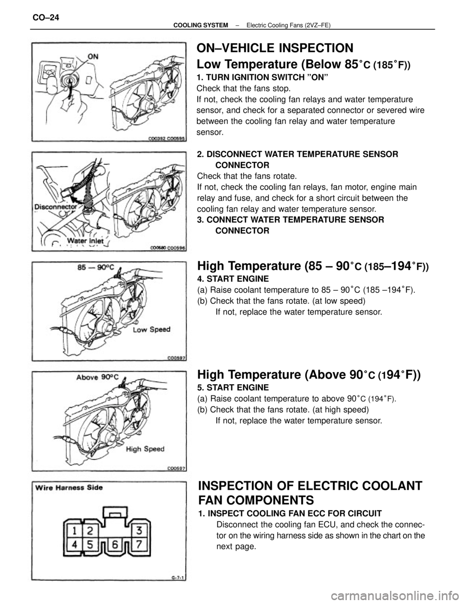
ON±VEHICLE INSPECTION
Low Temperature (Below 85
°C (185°F))
1. TURN IGNITION SWITCH ºONº
Check that the fans stop.
If not, check the cooling fan relays and water temperature
sensor, and check for a separated connector or severed wire
between the cooling fan relay and water temperature
sensor.
2. DISCONNECT WATER TEMPERATURE SENSOR
CONNECTOR
Check that the fans rotate.
If not, check the cooling fan relays, fan motor, engine main
relay and fuse, and check for a short circuit between the
cooling fan relay and water temperature sensor.
3. CONNECT WATER TEMPERATURE SENSOR
CONNECTOR
INSPECTION OF ELECTRIC COOLANT
FAN COMPONENTS
1. INSPECT COOLING FAN ECC FOR CIRCUIT
Disconnect the cooling fan ECU, and check the connec-
tor on the wiring harness side as shown in the chart on the
next page.
High Temperature (85 ± 90°C (185±194°F))
4. START ENGINE
(a) Raise coolant temperature to 85 ± 90°C (185 ±194°F).
(b) Check that the fans rotate. (at low speed)
If not, replace the water temperature sensor.
High Temperature (Above 90°C (194°F))
5. START ENGINE
(a) Raise coolant temperature to above 90
°C (194°F).
(b) Check that the fans rotate. (at high speed)
If not, replace the water temperature sensor.
± COOLING SYSTEMElectric Cooling Fans (2VZ±FE)CO±24
Page 1012 of 2389
5. INSPECT NO±2 COOLING FAN RELAY
(ºAC FAN NO.2º)
A. Inspect relay continuity
(a) Using an ohmmeter, check that there is continuity between
terminals 2 and 6.
(b) Check that there is continuity between terminals 1 and 3.
(c) Check that there is no continuity between terminals 1
and 4.
If continuity is not as specified, replace the relay. 2. INSPECT WATER TEMPERATURE SENSOR
Using an ohmmeter, measure the resistance between the
terminals.
Resistance:
Approx. 1.53 k� at 80°C (176° F)
Approx. 1.18 k� at 90°C (194° F)
Approx. 1.03 k� at 95°C (203°F)
If resistance is not as specified, replace the sensor.
3. INSPECT ENGINE MAIN RELAY (See page CH±16)
4. INSPECT NO.1 COOLING FAN RELAY (ºFAN NO.1 º)
(See page CO±22)
Ignition switch ON Ignition switch ON Tester connectionSpecified valve Condition
Battery voltageBattery voltage
Coolant temp.
Continuity
ContinuityContinuity ResistanceContinuity Check for
Voltage
Voltage
± COOLING SYSTEMElectric Cooling Fans (2VZ±FE)CO±25
Page 1017 of 2389
The ER system is composed of there basic sub±systems: Fuel, Air Induction and Electronic Control Systems.
FUEL SYSTEM
Fuel is supplied under constant pressure to the EFI injectors by an electric fuel pump. The injectors inject a
metered quantity of fuel into the intake manifold in a accordance with signals from the ECU (Electronic Control
Unit).
AIR INDUCTION SYSTEM
The air induction system provides sufficient air for engine operation.
ELECTRONIC CONTROL SYSTEM
The Camry 3S±FE and 2V1±FE engines are equipped with a Toyota Computer Control System (TCCS) which
centrally controls the EFI, ESA, ISC, Diagnosis systems etc. by means of an Electronic Control Unit (ECU±
formerly ER computer) employing a microcomputer.
By means of the ECU, the TCCS controls the following functions:
1. Electronic Fuel Injection (EFI)
The ECU receives signals from various sensors indicating changing engine operation conditions such as:
Intake air volume
Intake air temperature
Coolant temperature
Engine rpm
Acceleration/deceleration
Exhaust oxygen content etc.
The signals are utilized by the ECU to determine the injection duration necessary for an optimum air±fuel ratio.
2. Electronic Spark Advance (ESA)
The ECU is programmed with data for optimum ignition timing under any and all operating conditions.
Using data provided by sensors which monitor various engine functions (rpm, coolant temperature, etc.), the
microcomputer (ECU) triggers the spark at precisely the right instant. (See IG section)
3. Idle Speed Control (ISC)
The ECU is programmed with target idling speed values to respond to different engine conditions (coolant
temperature, air conditioner ON/OFF, etc.). Sensors transmit signals to the ECU which control the flow of air
through the by±pass of the throttle valve and adjust idle speed to the target value. (See page FI±45,115
or 62, 117)
4. Diagnosis
The ECU detects any malfunctions or abnormalities in the sensor network and lights a ºCHECKº engine warn-
ing light on the instrument panel. At the same time, the trouble is identified and a diagnosis code is recorded
by the ECU. The diagnosis code can be read by the number of blinks of the ºCHECKº engine warning light
when terminals TE1 and E1 are connected. The diagnostic codes are refer to the later page.
(See page FI±25 or 27)
5. Fail±safe Function
In the event of the sensor malfunctioning, a back±up circuit will take over to provide minimal drivability, and
the ºCHECKº engine warning light.
± EFI SYSTEMSystem DescriptionFI±4
Page 1040 of 2389
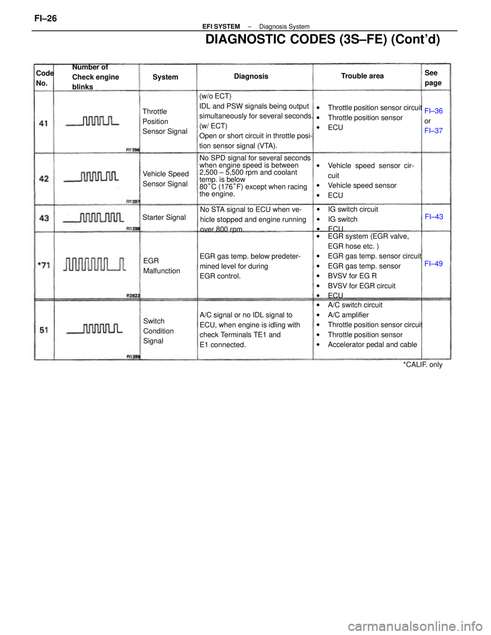
(w/o ECT)
IDL and PSW signals being output
simultaneously for several seconds.
(w/ ECT)
Open or short circuit in throttle posi-
tion sensor signal (VTA).
wEGR system (EGR valve,
EGR hose etc. )
wEGR gas temp. sensor circuit
wEGR gas temp. sensor
wBVSV for EG R
wBVSV for EGR circuit
wECU
wA/C switch circuit
wA/C amplifier
wThrottle position sensor circuit
wThrottle position sensor
wAccelerator pedal and cable No SPD signal for several seconds
when engine speed is between
2,500 ± 5,500 rpm and coolant
temp. is below
80°C (176°F) except when racing
the engine.
DIAGNOSTIC CODES (3S±FE) (Cont'd)
A/C signal or no IDL signal to
ECU, when engine is idling with
check Terminals TE1 and
E1 connected.wThrottle position sensor circuit
wThrottle position sensor
wECU
wVehicle speed sensor cir-
cuit
wVehicle speed sensor
wECU
EGR gas temp. below predeter-
mined level for during
EGR control.No STA signal to ECU when ve-
hicle stopped and engine running
over 800 rpm.wIG switch circuit
wIG switch
wECU Number of
Check engine
blinks
Throttle
Position
Sensor Signal
Switch
Condition
Signal Vehicle Speed
Sensor Signal
EGR
Malfunction Starter Signal
*CALIF. only Trouble area
FI±36
or
FI±37 DiagnosisSee
page Code
No.System
FI±49FI±43
± EFI SYSTEMDiagnosis SystemFI±26
Page 1042 of 2389
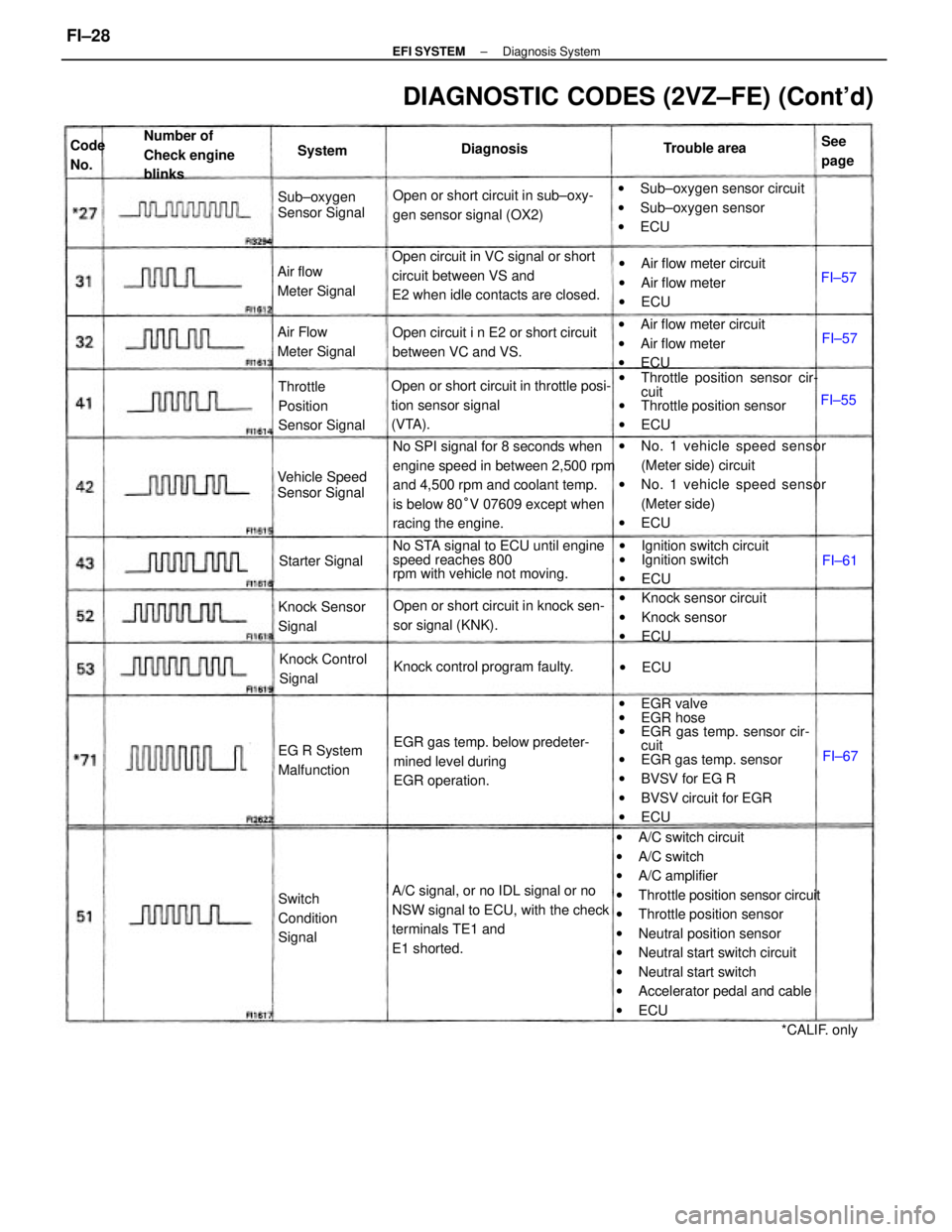
wA/C switch circuit
wA/C switch
wA/C amplifier
wThrottle position sensor circuit
wThrottle position sensor
wNeutral position sensor
wNeutral start switch circuit
wNeutral start switch
wAccelerator pedal and cable
wECU wEGR valve
wEGR hose
wEGR gas temp. sensor cir-
cuit
wEGR gas temp. sensor
wBVSV for EG R
wBVSV circuit for EGR
wECU No SPI signal for 8 seconds when
engine speed in between 2,500 rpm
and 4,500 rpm and coolant temp.
is below 80°V 07609 except when
racing the engine.wNo. 1 vehicle speed sensor
(Meter side) circuit
wNo. 1 vehicle speed sensor
(Meter side)
wECU
A/C signal, or no IDL signal or no
NSW signal to ECU, with the check
terminals TE1 and
E1 shorted. Open circuit in VC signal or short
circuit between VS and
E2 when idle contacts are closed.
wThrottle position sensor cir-
cuit
wThrottle position sensor
wECU
DIAGNOSTIC CODES (2VZ±FE) (Cont'd)
Open or short circuit in throttle posi-
tion sensor signal
(VTA).
No STA signal to ECU until engine
speed reaches 800
rpm with vehicle not moving.
EGR gas temp. below predeter-
mined level during
EGR operation.wSub±oxygen sensor circuit
wSub±oxygen sensor
wECU Open or short circuit in sub±oxy-
gen sensor signal (OX2)
wIgnition switch circuit
wIgnition switch
wECU wAir flow meter circuit
wAir flow meter
wECU wAir flow meter circuit
wAir flow meter
wECU
Open or short circuit in knock sen-
sor signal (KNK).wKnock sensor circuit
wKnock sensor
wECU Open circuit i n E2 or short circuit
between VC and VS.
Knock control program faulty. Throttle
Position
Sensor Signal Number of
Check engine
blinks
Knock Sensor
Signal
Switch
Condition
SignalKnock Control
Signal Air Flow
Meter Signal
Vehicle Speed
Sensor Signal Air flow
Meter SignalSub±oxygen
Sensor Signal
EG R System
MalfunctionStarter Signal
*CALIF. only Trouble area
DiagnosisSee
page System Code
No.
wECUFI±55FI±57
FI±57
FI±67 FI±61
± EFI SYSTEMDiagnosis SystemFI±28
Page 1057 of 2389
No trouble (ºCHECKº engine warning light off) and
engine running
Voltage at ECU Wiring Connectors (3S±FE)
Measuring plate fully closed
Intake air temp. 20°C (68°F)
Coolant temp. 80°C (1765F) Measuring plate fully open Throttle valve fully closed Throttle valve fully closed
Throttle valve open
Air conditioning ONThrottle valve open Throttle valve open
Cranking or idlingSTD voltage (V)
Terminals
3,000 rpmSee page Condition
IG SW ONIG SW ON
IG SW ON
IG
SW ONIG SW ON
IG SW ONCrankingIdling
FI±40
FI±44
FI±46FI±45FI±34
FI±43 FI±42
FI±47FI±35
FI±36
FI±37
FI±39
FI±41 No.
± EFI SYSTEMTroubleshooting with Volt OhmmeterFI±33
Page 1066 of 2389
Check that there is voltage between ECU terminal +B or +131 and
body ground. (IG SW ON)
No voltage between ECU terminals THW
and E2.
(IG SW ON)
Check wiring between ECU terminal El and body
ground.
Check wiring between ECU and water
temp. sensor. Check water temp. sensor.
(See page FI± 1 Z5)Coolant temperature 8O° (176°F)
Refer to NO. 1.
(See page FI±34)
Replace water
temp. sensor.Repair or replace.
Repair or replace.
Try another ECU.STD voltage
No voltage
IG SW ON Terminals
Condition Trouble
BAD
BAD
BAD
No.
± EFI SYSTEMTroubleshooting with Volt OhmmeterFI±42