Page 824 of 2389

1. INSPECT RELAY OPERATION (ANTENNA UP)
(a) Connect the voltmeter positive (+) lead to terminal 1
and the negative (±) lead to terminal 4.
(b) Connect the positive (+) lead from the battery to terminals
6, 7 and 8. Connect the negative (±) lead to terminal 3.
(c) Check that there is battery voltage.
HINT: Measure the voltage within 7 seconds after con±
necting the positive (+) battery lead to terminals 8.
2. INSPECT RELAY OPERATION (ANTENNA DOWN)
(a) Connect the voltmeter positive (+) lead to terminal 4
and the negative (±) lead to terminal 1.
(b) Connect the positive (+) lead from the battery to terminals
6 and 7. Connect the negative (±) lead to terminal 2.
(e) Disconnect the positive (+) battery lead from terminal 6.
(d) Check that there is battery voltage.
HINT: Measure the voltage within 7 seconds after disconnect±
ing the positive (+) battery lead from terminal 6.
3. INSPECT RELAY OPERATION (ANTENNA STOP)
(a) Connect the voltmeter positive (+) lead to terminal 1
and the negative (±) lead to terminal 4.
(b) Connect the positive (+) lead from the ±battery to termi-
nals 7 and 9. Connect the negative (±) lead to terminal 2.
(c) Check that there is no battery voltage.
If operation is not as specified, replace the relay.
Antenna Motor
INSPECTION OF ANTENNA MOTOR
INSPECT LIMIT SWITCH OPERATION
(a) If the motor stops with the antenna up, check that
there is no continuity between terminals A±2 and
B±1.
(b) If the motor stops with the antenna down, check that
there is no continuity between terminals A±3 and
B±1.
If continuity is not as specified, replace the motor.
Antenna Motor Control Relay
INSPECTION OF ANTENNA MOTOR
CONTROL RELAY
± BODY ELECTRICAL SYSTEMAudio SystemBE±102
Page 944 of 2389

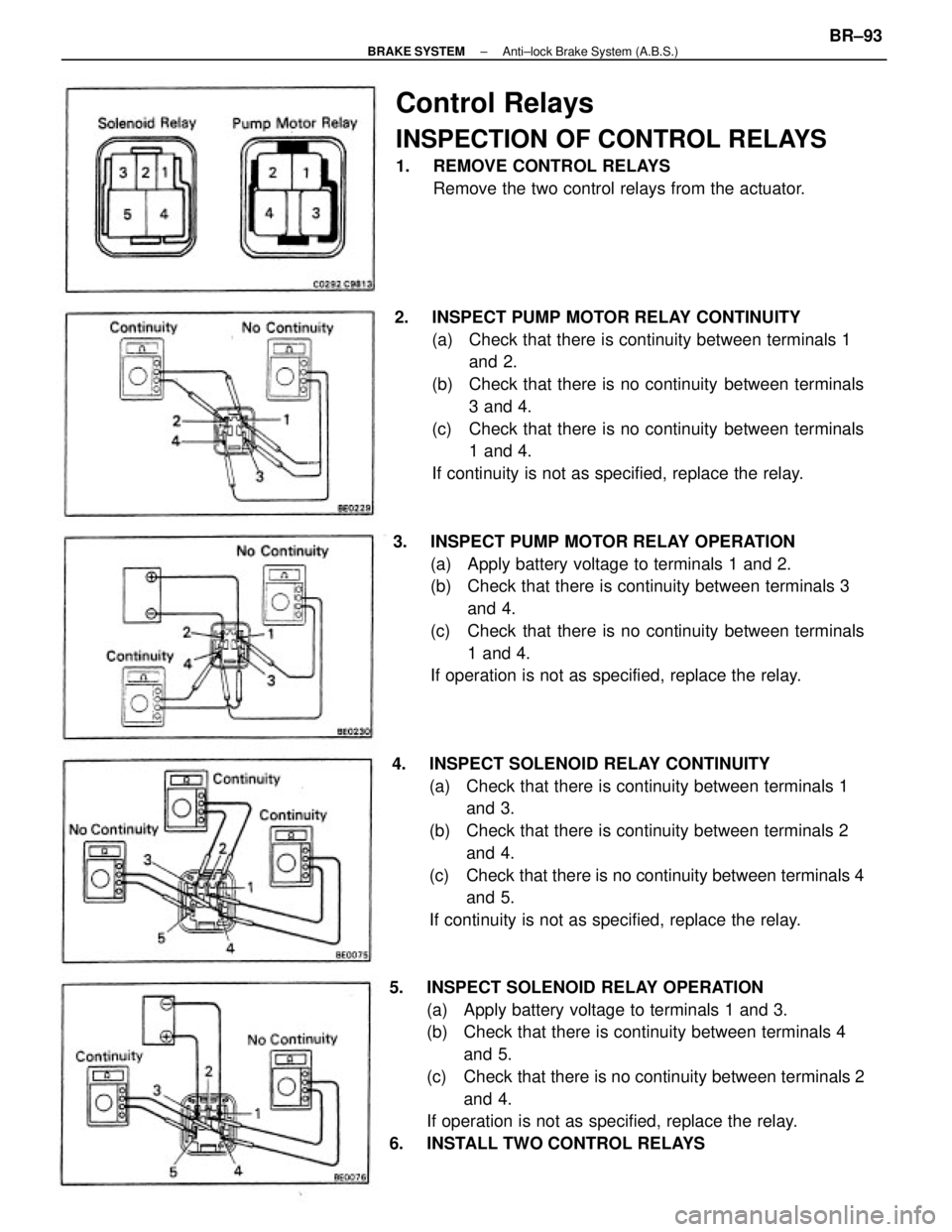
5. INSPECT SOLENOID RELAY OPERATION
(a) Apply battery voltage to terminals 1 and 3.
(b) Check that there is continuity between terminals 4
and 5.
(c) Check that there is no continuity between terminals 2
and 4.
If operation is not as specified, replace the relay.
6. INSTALL TWO CONTROL RELAYS4. INSPECT SOLENOID RELAY CONTINUITY
(a) Check that there is continuity between terminals 1
and 3.
(b) Check that there is continuity between terminals 2
and 4.
(c) Check that there is no continuity between terminals 4
and 5.
If continuity is not as specified, replace the relay. 2. INSPECT PUMP MOTOR RELAY CONTINUITY
(a) Check that there is continuity between terminals 1
and 2.
(b) Check that there is no continuity between terminals
3 and 4.
(c) Check that there is no continuity between terminals
1 and 4.
If continuity is not as specified, replace the relay.
3. INSPECT PUMP MOTOR RELAY OPERATION
(a) Apply battery voltage to terminals 1 and 2.
(b) Check that there is continuity between terminals 3
and 4.
(c) Check that there is no continuity between terminals
1 and 4.
If operation is not as specified, replace the relay.
Control Relays
INSPECTION OF CONTROL RELAYS
1. REMOVE CONTROL RELAYS
Remove the two control relays from the actuator.
± BRAKE SYSTEMAnti±lock Brake System (A.B.S.)BR±93
Page 963 of 2389
1. INSPECT RELAY CONTINUITY
(a) Using an ohmmeter, check that there is continuity between
terminals 1 and 3.
(b) Check that there is continuity between terminals 2 and
4.
(c) Check that there is no continuity between terminals 4
and 5.
If continuity is not as specified, replace the relay.
2. INSPECT RELAY OPERATION
(a) Apply battery voltage across terminals 1 and 3.
(b) Using an ohmmeter, check that there is continuity between
terminals 4 and 5.
(e) Check that there is no continuity between terminals 2
and 4.
If operation is not as specified, replace the relay.
ENGINE MAIN RELAY
INSPECTION OF ENGINE MAIN RELAY
LOCATION:
3S±FE In the relay box in the engine compartment.
2VZ±FE On the LH fender apron rear side in the engine
compartment.
± CHARGING SYSTEMEngine Main RelayCH±16
Page 1009 of 2389

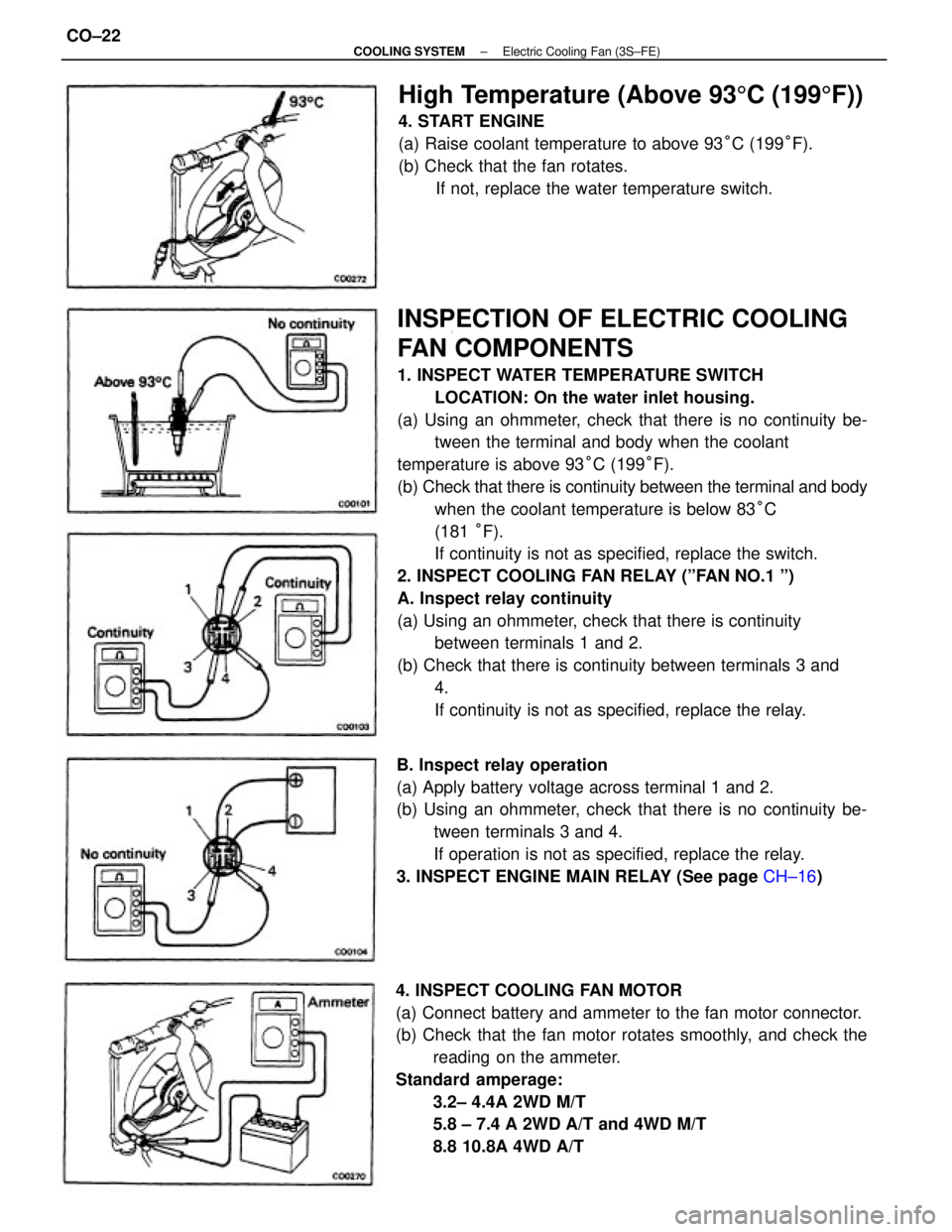
INSPECTION OF ELECTRIC COOLING
FAN COMPONENTS
1. INSPECT WATER TEMPERATURE SWITCH
LOCATION: On the water inlet housing.
(a) Using an ohmmeter, check that there is no continuity be-
tween the terminal and body when the coolant
temperature is above 93°C (199°F).
(b) Check that there is continuity between the terminal and body
when the coolant temperature is below 83°C
(181 °F).
If continuity is not as specified, replace the switch.
2. INSPECT COOLING FAN RELAY (ºFAN NO.1 º)
A. Inspect relay continuity
(a) Using an ohmmeter, check that there is continuity
between terminals 1 and 2.
(b) Check that there is continuity between terminals 3 and
4.
If continuity is not as specified, replace the relay.
4. INSPECT COOLING FAN MOTOR
(a) Connect battery and ammeter to the fan motor connector.
(b) Check that the fan motor rotates smoothly, and check the
reading on the ammeter.
Standard amperage:
3.2± 4.4A 2WD M/T
5.8 ± 7.4 A 2WD A/T and 4WD M/T
8.8 10.8A 4WD A/T B. Inspect relay operation
(a) Apply battery voltage across terminal 1 and 2.
(b) Using an ohmmeter, check that there is no continuity be-
tween terminals 3 and 4.
If operation is not as specified, replace the relay.
3. INSPECT ENGINE MAIN RELAY (See page CH±16)
High Temperature (Above 935C (1995F))
4. START ENGINE
(a) Raise coolant temperature to above 93°C (199°F).
(b) Check that the fan rotates.
If not, replace the water temperature switch.
± COOLING SYSTEMElectric Cooling Fan (3S±FE)CO±22
Page 1011 of 2389

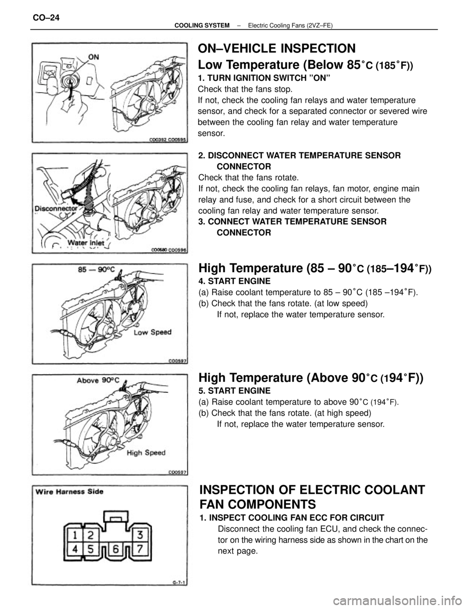
ON±VEHICLE INSPECTION
Low Temperature (Below 85
°C (185°F))
1. TURN IGNITION SWITCH ºONº
Check that the fans stop.
If not, check the cooling fan relays and water temperature
sensor, and check for a separated connector or severed wire
between the cooling fan relay and water temperature
sensor.
2. DISCONNECT WATER TEMPERATURE SENSOR
CONNECTOR
Check that the fans rotate.
If not, check the cooling fan relays, fan motor, engine main
relay and fuse, and check for a short circuit between the
cooling fan relay and water temperature sensor.
3. CONNECT WATER TEMPERATURE SENSOR
CONNECTOR
INSPECTION OF ELECTRIC COOLANT
FAN COMPONENTS
1. INSPECT COOLING FAN ECC FOR CIRCUIT
Disconnect the cooling fan ECU, and check the connec-
tor on the wiring harness side as shown in the chart on the
next page.
High Temperature (85 ± 90°C (185±194°F))
4. START ENGINE
(a) Raise coolant temperature to 85 ± 90°C (185 ±194°F).
(b) Check that the fans rotate. (at low speed)
If not, replace the water temperature sensor.
High Temperature (Above 90°C (194°F))
5. START ENGINE
(a) Raise coolant temperature to above 90
°C (194°F).
(b) Check that the fans rotate. (at high speed)
If not, replace the water temperature sensor.
± COOLING SYSTEMElectric Cooling Fans (2VZ±FE)CO±24
Page 1012 of 2389
5. INSPECT NO±2 COOLING FAN RELAY
(ºAC FAN NO.2º)
A. Inspect relay continuity
(a) Using an ohmmeter, check that there is continuity between
terminals 2 and 6.
(b) Check that there is continuity between terminals 1 and 3.
(c) Check that there is no continuity between terminals 1
and 4.
If continuity is not as specified, replace the relay. 2. INSPECT WATER TEMPERATURE SENSOR
Using an ohmmeter, measure the resistance between the
terminals.
Resistance:
Approx. 1.53 k� at 80°C (176° F)
Approx. 1.18 k� at 90°C (194° F)
Approx. 1.03 k� at 95°C (203°F)
If resistance is not as specified, replace the sensor.
3. INSPECT ENGINE MAIN RELAY (See page CH±16)
4. INSPECT NO.1 COOLING FAN RELAY (ºFAN NO.1 º)
(See page CO±22)
Ignition switch ON Ignition switch ON Tester connectionSpecified valve Condition
Battery voltageBattery voltage
Coolant temp.
Continuity
ContinuityContinuity ResistanceContinuity Check for
Voltage
Voltage
± COOLING SYSTEMElectric Cooling Fans (2VZ±FE)CO±25
Page 1013 of 2389
B. Inspect relay operation
(a) Apply battery voltage across terminal 2 and 6.
(b) Using an ohmmeter, check that there is no continuity be-
tween terminals 1 and 3.
(c) Check that there is continuity between terminals 1 and 4.
If operation is not as specified, replace the relay.
6. INSPECT No.3 COOLING FAN RELAY
(ºAC FAN NO.3º)
(See procedure EFI Main Relay on page FI±122)
7. INSPECT COOLING FAN MOTORS
(a) Connect battery and ammeter to the fan motor connector.
(b) Check that the fan motor rotates smoothly, and check the
reading on the ammeter.
Standard amperage: No. 1 12.1 ±15.1A
No.2 6.0±7.4A
± COOLING SYSTEMElectric Cooling Fans (2VZ±FE)CO±26
Page 1027 of 2389

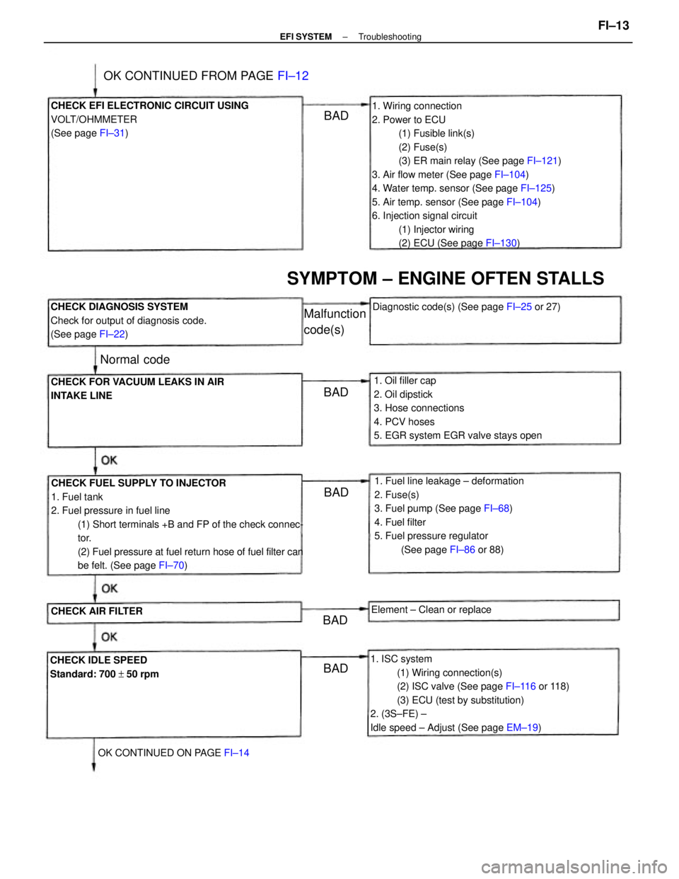
1. Wiring connection
2. Power to ECU
(1) Fusible link(s)
(2) Fuse(s)
(3) ER main relay (See page FI±121)
3. Air flow meter (See page FI±104)
4. Water temp. sensor (See page FI±125)
5. Air temp. sensor (See page FI±104)
6. Injection signal circuit
(1) Injector wiring
(2) ECU (See page FI±130)
CHECK FUEL SUPPLY TO INJECTOR
1. Fuel tank
2. Fuel pressure in fuel line
(1) Short terminals +B and FP of the check connec-
tor.
(2) Fuel pressure at fuel return hose of fuel filter can
be felt. (See page FI±70)
1. ISC system
(1) Wiring connection(s)
(2) ISC valve (See page FI±116 or 118)
(3) ECU (test by substitution)
2. (3S±FE) ±
Idle speed ± Adjust (See page EM±19) 1. Fuel line leakage ± deformation
2. Fuse(s)
3. Fuel pump (See page FI±68)
4. Fuel filter
5. Fuel pressure regulator
(See page FI±86 or 88) 1. Oil filler cap
2. Oil dipstick
3. Hose connections
4. PCV hoses
5. EGR system EGR valve stays open CHECK EFI ELECTRONIC CIRCUIT USING
VOLT/OHMMETER
(See page FI±31)
CHECK DIAGNOSIS SYSTEM
Check for output of diagnosis code.
(See page FI±22)
CHECK FOR VACUUM LEAKS IN AIR
INTAKE LINE
SYMPTOM ± ENGINE OFTEN STALLS
CHECK IDLE SPEED
Standard: 700 + 50 rpmDiagnostic code(s) (See page FI±25 or 27)
OK CONTINUED FROM PAGE FI±12
OK CONTINUED ON PAGE FI±14Element ± Clean or replace
CHECK AIR FILTER
Malfunction
code(s)
Normal code
BADBAD
BAD
BADBAD
± EFI SYSTEMTroubleshootingFI±13