Page 1286 of 2389
15. DISCONNECT HOSES
(a) Two heater water by±pass hoses
(b) Two fuel hoses
NOTICE: Catch leaking fuel in a container.
(c) Brake booster vacuum hose
(d) A/C control valve vacuum hoses
(e) Charcoal canister vacuum hose
16. DISCONNECT WIRES AND CONNECTORS
(a) Check connector
(b) Ground straps from LH fender apron
(e) Connectors from relay box
(d) Engine room wire connector
17. RAISE VEHICLE
NOTICE: Be sure the vehicle is securely supported.
18. REMOVE ENGINE UNDER COVERS
19. DRAIN ENGINE OIL (See page LU±7)
20. REMOVE SUSPENSION LOWER CROSSMEMBER
Remove the four bolts, two nuts and crossmember.
21. REMOVE DRIVE SHAFTS
22. (4WD) .
REMOVE PROPELLER SHAFT
23. (4WD)
REMOVE DEFECTOR FROM TRANSFER EXTENSION
HOUSING
24. REMOVE PS PUMP WITHOUT DISCONNECTING
HOSES
HINT: Put aside the pump and suspend it to the cowl with a
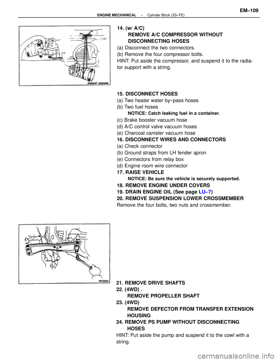
string.14. (w/ A/C)
REMOVE A/C COMPRESSOR WITHOUT
DISCONNECTING HOSES
(a) Disconnect the two connectors.
(b) Remove the four compressor bolts.
HINT: Put aside the compressor, and suspend it to the radia-
tor support with a string.
± ENGINE MECHANICALCylinder Block (3S±FE)EM±109
Page 1313 of 2389
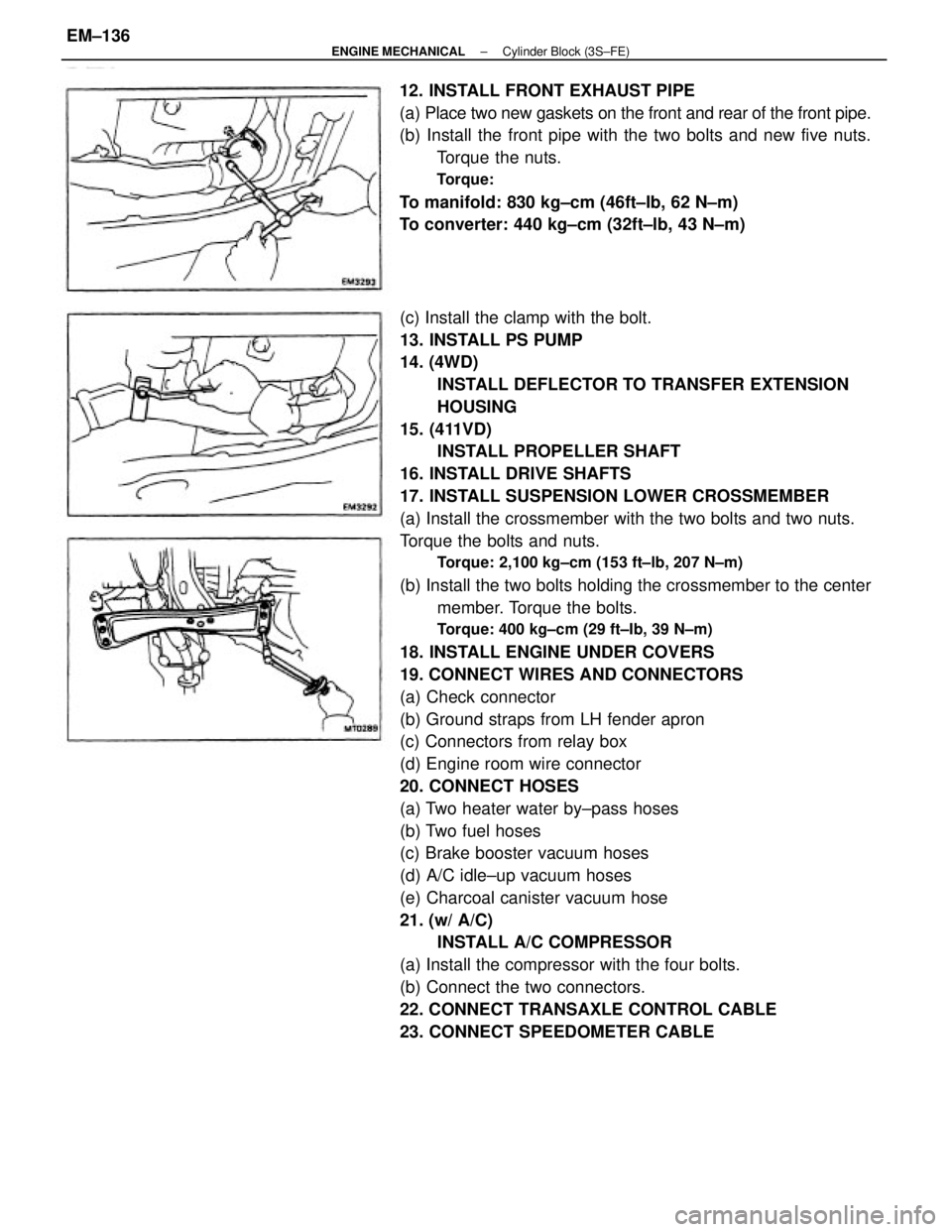
(c) Install the clamp with the bolt.
13. INSTALL PS PUMP
14. (4WD)
INSTALL DEFLECTOR TO TRANSFER EXTENSION
HOUSING
15. (411VD)
INSTALL PROPELLER SHAFT
16. INSTALL DRIVE SHAFTS
17. INSTALL SUSPENSION LOWER CROSSMEMBER
(a) Install the crossmember with the two bolts and two nuts.
Torque the bolts and nuts.
Torque: 2,100 kg±cm (153 ft±lb, 207 N±m)
(b) Install the two bolts holding the crossmember to the center
member. Torque the bolts.
Torque: 400 kg±cm (29 ft±Ib, 39 N±m)
18. INSTALL ENGINE UNDER COVERS
19. CONNECT WIRES AND CONNECTORS
(a) Check connector
(b) Ground straps from LH fender apron
(c) Connectors from relay box
(d) Engine room wire connector
20. CONNECT HOSES
(a) Two heater water by±pass hoses
(b) Two fuel hoses
(c) Brake booster vacuum hoses
(d) A/C idle±up vacuum hoses
(e) Charcoal canister vacuum hose
21. (w/ A/C)
INSTALL A/C COMPRESSOR
(a) Install the compressor with the four bolts.
(b) Connect the two connectors.
22. CONNECT TRANSAXLE CONTROL CABLE
23. CONNECT SPEEDOMETER CABLE 12. INSTALL FRONT EXHAUST PIPE
(a) Place two new gaskets on the front and rear of the front pipe.
(b) Install the front pipe with the two bolts and new five nuts.
Torque the nuts.
Torque:
To manifold: 830 kg±cm (46ft±Ib, 62 N±m)
To converter: 440 kg±cm (32ft±lb, 43 N±m)
± ENGINE MECHANICALCylinder Block (3S±FE)EM±136
Page 1319 of 2389
25. DISCONNECT ENGINE WIRE FROM CABIN
(a) Remove the under cover.
(b) Remove the glove compartment box.
(c) Disconnect the following connectors:
(1) Three engine & ECT ECU connectors
(2) Circuit opening relay connector
(3) Cowl wire connector
(4) Instrument panel wire connector
(d) Pull out the engine wire from the cowl panel.
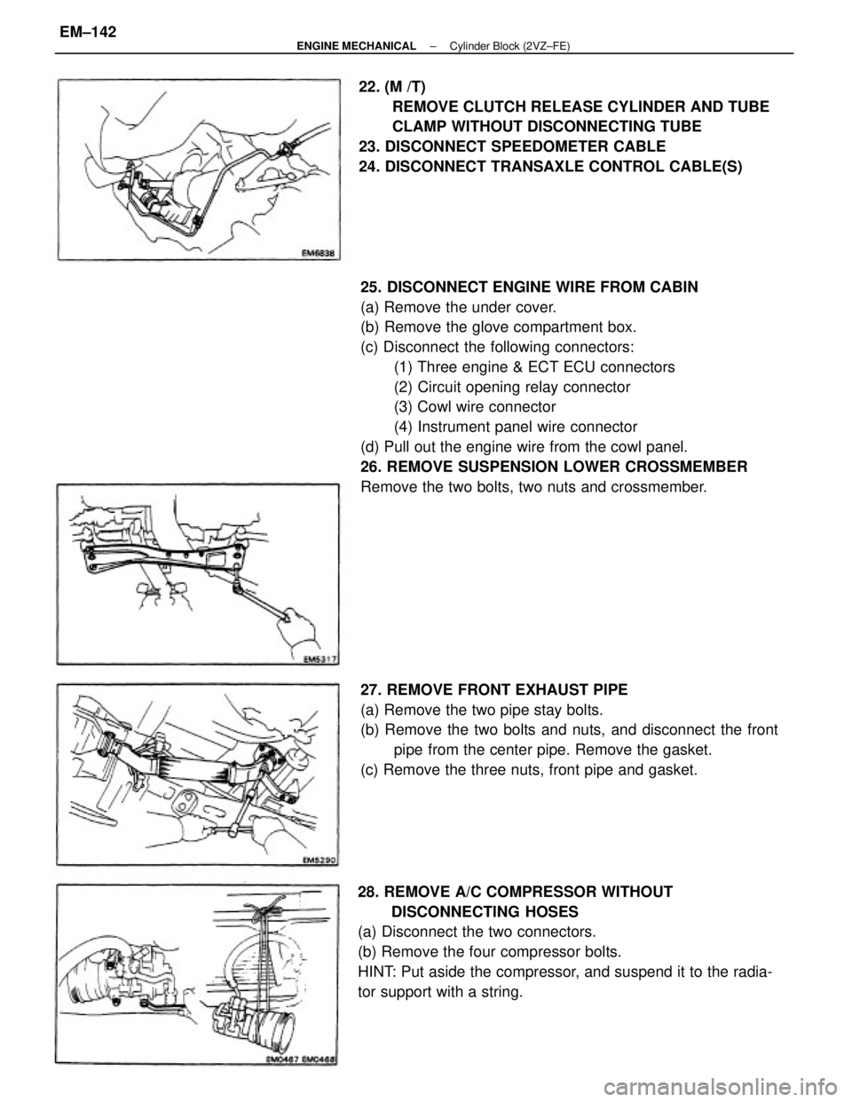
26. REMOVE SUSPENSION LOWER CROSSMEMBER
Remove the two bolts, two nuts and crossmember.
28. REMOVE A/C COMPRESSOR WITHOUT
DISCONNECTING HOSES
(a) Disconnect the two connectors.
(b) Remove the four compressor bolts.
HINT: Put aside the compressor, and suspend it to the radia-
tor support with a string.22. (M /T)
REMOVE CLUTCH RELEASE CYLINDER AND TUBE
CLAMP WITHOUT DISCONNECTING TUBE
23. DISCONNECT SPEEDOMETER CABLE
24. DISCONNECT TRANSAXLE CONTROL CABLE(S)
27. REMOVE FRONT EXHAUST PIPE
(a) Remove the two pipe stay bolts.
(b) Remove the two bolts and nuts, and disconnect the front
pipe from the center pipe. Remove the gasket.
(c) Remove the three nuts, front pipe and gasket.
± ENGINE MECHANICALCylinder Block (2VZ±FE)EM±142
Page 1349 of 2389
16. CONNECT ENGINE WIRE TO CABIN
(a) Push in the engine wire through the cowl panel.
(b) Connect the following connectors.
(1) Three TCCS ECU connectors
(2) Circuit opening relay connector
(3) Cowl wire connector
(4) Instrument panel wire connector
(c) Install the glove compartment box.
(d) Install the under cover.
17. CONNECT TRANSAXLE CONTROL CABLE(S)
18. CONNECT SPEEDOMETER CABLE
19. (M /T)
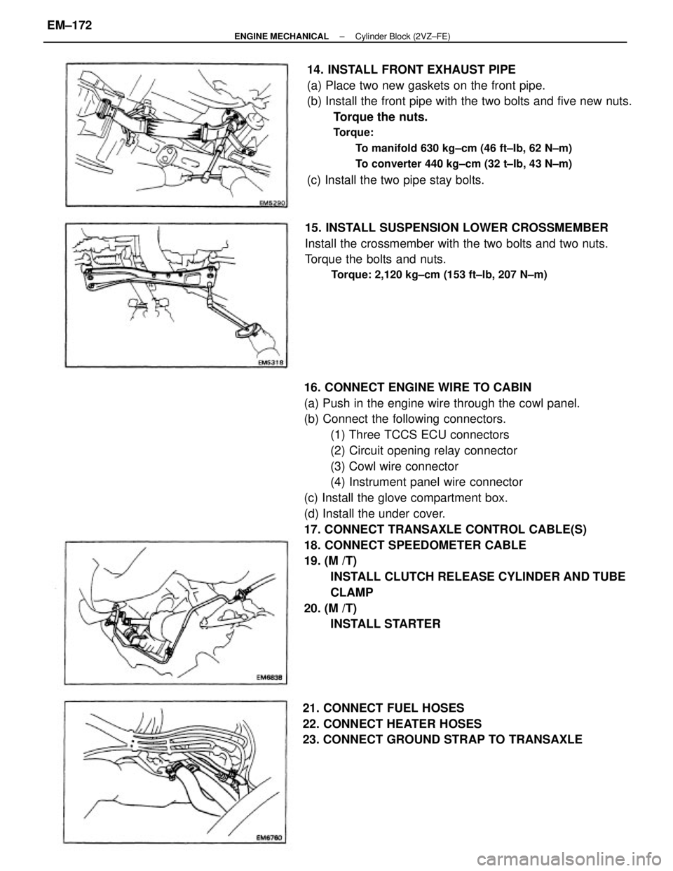
INSTALL CLUTCH RELEASE CYLINDER AND TUBE
CLAMP
20. (M /T)
INSTALL STARTER 14. INSTALL FRONT EXHAUST PIPE
(a) Place two new gaskets on the front pipe.
(b) Install the front pipe with the two bolts and five new nuts.
Torque the nuts.
Torque:
To manifold 630 kg±cm (46 ft±Ib, 62 N±m)
To converter 440 kg±cm (32 t±Ib, 43 N±m)
(c) Install the two pipe stay bolts.
15. INSTALL SUSPENSION LOWER CROSSMEMBER
Install the crossmember with the two bolts and two nuts.
Torque the bolts and nuts.
Torque: 2,120 kg±cm (153 ft±lb, 207 N±m)
21. CONNECT FUEL HOSES
22. CONNECT HEATER HOSES
23. CONNECT GROUND STRAP TO TRANSAXLE
± ENGINE MECHANICALCylinder Block (2VZ±FE)EM±172
Page 1358 of 2389
FRONT AXLE AND
SUSPENSION
FRONT AXLE AND SUSPENSIONFA ± 1
Page 1359 of 2389
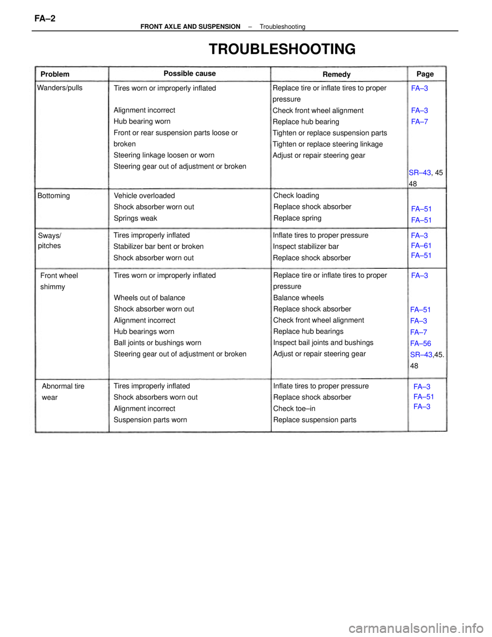
Replace tire or inflate tires to proper
pressure
Check front wheel alignment
Replace hub bearing
Tighten or replace suspension parts
Tighten or replace steering linkage
Adjust or repair steering gear
Replace tire or inflate tires to proper
pressure
Balance wheels
Replace shock absorber
Check front wheel alignment
Replace hub bearings
Inspect bail joints and bushings
Adjust or repair steering gear Wheels out of balance
Shock absorber worn out
Alignment incorrect
Hub bearings worn
Ball joints or bushings worn
Steering gear out of adjustment or broken Alignment incorrect
Hub bearing worn
Front or rear suspension parts loose or
broken
Steering linkage loosen or worn
Steering gear out of adjustment or broken
Inflate tires to proper pressure
Replace shock absorber
Check toe±in
Replace suspension parts Tires improperly inflated
Shock absorbers worn out
Alignment incorrect
Suspension parts wornInflate tires to proper pressure
Inspect stabilizer bar
Replace shock absorber Tires improperly inflated
Stabilizer bar bent or broken
Shock absorber worn outVehicle overloaded
Shock absorber worn out
Springs weakCheck loading
Replace shock absorber
Replace spring
FA±51
FA±3
FA±7
FA±56
SR±43,45.
48
TROUBLESHOOTING
Tires worn or improperly inflatedTires worn or improperly inflated
Abnormal tire
wear Front wheel
shimmyFA±3
FA±61
FA±51
FA±3
FA±51
FA±3 SR±43, 45
48 Possible cause
Sways/
pitches Wanders/pulls
FA±51
FA±51 BottomingFA±3
FA±7 Problem
RemedyPage
FA±3
FA±3
± FRONT AXLE AND SUSPENSIONTroubleshootingFA ± 2
Page 1360 of 2389
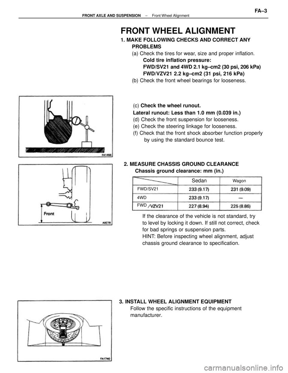
FRONT WHEEL ALIGNMENT
1. MAKE FOLLOWING CHECKS AND CORRECT ANY
PROBLEMS
(a) Check the tires for wear, size and proper inflation.
Cold tire inflation pressure:
FWD/SV21 and 4WD 2.1 kg±cm2 (30 psi, 206 kPa)
FWD/VZV21 2.2 kg±cm2 (31 psi, 216 kPa)
(b) Check the front wheel bearings for looseness.
(c) Check the wheel runout.
Lateral runout: Less than 1.0 mm (0.039 in.)
(d) Check the front suspension for looseness.
(e) Check the steering linkage for looseness.
(f) Check that the front shock absorber function properly
by using the standard bounce test.
If the clearance of the vehicle is not standard, try
to level by locking it down. If still not correct, check
for bad springs or suspension parts.
HINT: Before inspecting wheel alignment, adjust
chassis ground clearance to specification.
3. INSTALL WHEEL ALIGNMENT EQUIPMENT
Follow the specific instructions of the equipment
manufacturer. 2. MEASURE CHASSIS GROUND CLEARANCE
Chassis ground clearance: mm (in.)
FWD/SV21Wagon
Sedan
4WD
FWD
± FRONT AXLE AND SUSPENSIONFront Wheel AlignmentFA ± 3
Page 1361 of 2389
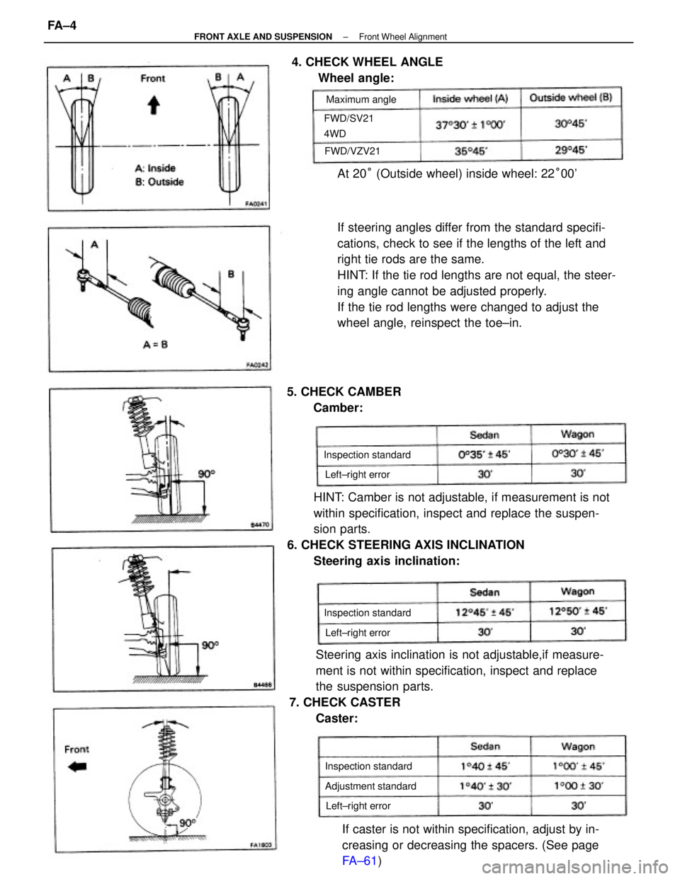
If steering angles differ from the standard specifi-
cations, check to see if the lengths of the left and
right tie rods are the same.
HINT: If the tie rod lengths are not equal, the steer-
ing angle cannot be adjusted properly.
If the tie rod lengths were changed to adjust the
wheel angle, reinspect the toe±in.
HINT: Camber is not adjustable, if measurement is not
within specification, inspect and replace the suspen-
sion parts.
6. CHECK STEERING AXIS INCLINATION
Steering axis inclination:
Steering axis inclination is not adjustable,if measure-
ment is not within specification, inspect and replace
the suspension parts.
7. CHECK CASTER
Caster:
If caster is not within specification, adjust by in-
creasing or decreasing the spacers. (See page
FA±61) At 20° (Outside wheel) inside wheel: 22°00' 4. CHECK WHEEL ANGLE
Wheel angle:
5. CHECK CAMBER
Camber:
Adjustment standard Inspection standard Inspection standard
Inspection standard FWD/SV21
4WDMaximum angle
Left±right error
Left±right error Left±right error FWD/VZV21
± FRONT AXLE AND SUSPENSIONFront Wheel AlignmentFA ± 4
