Page 1448 of 2389
Initial condition Retainer
Rubber Plug
Outer
Lock
Inner
Rubber Plug
A
Illustration from side BB OuterSpecial tool
Inner
B±19
TERMINAL AND CONNECTOR REPAIR±TERMINAL REPLACEMENT
29
Wire Harness Repair Manual (RM1022E)
(5)Move the retainer until it becomes the initial condition.
Type J
[Male]
(1)Remove the rubber plug.
(2)Push the lock of the inner using the special tool.
(3)Pull the wire to the direction of the arrow pushing the
lock up and remove the inner from the outer.
[Female]
(1)Remove the rubber plug.
(2)Insert the special tool into the outer shown in the
illustration. Then push the area A of the inner and
remove the inner from the outer.
Page 1461 of 2389

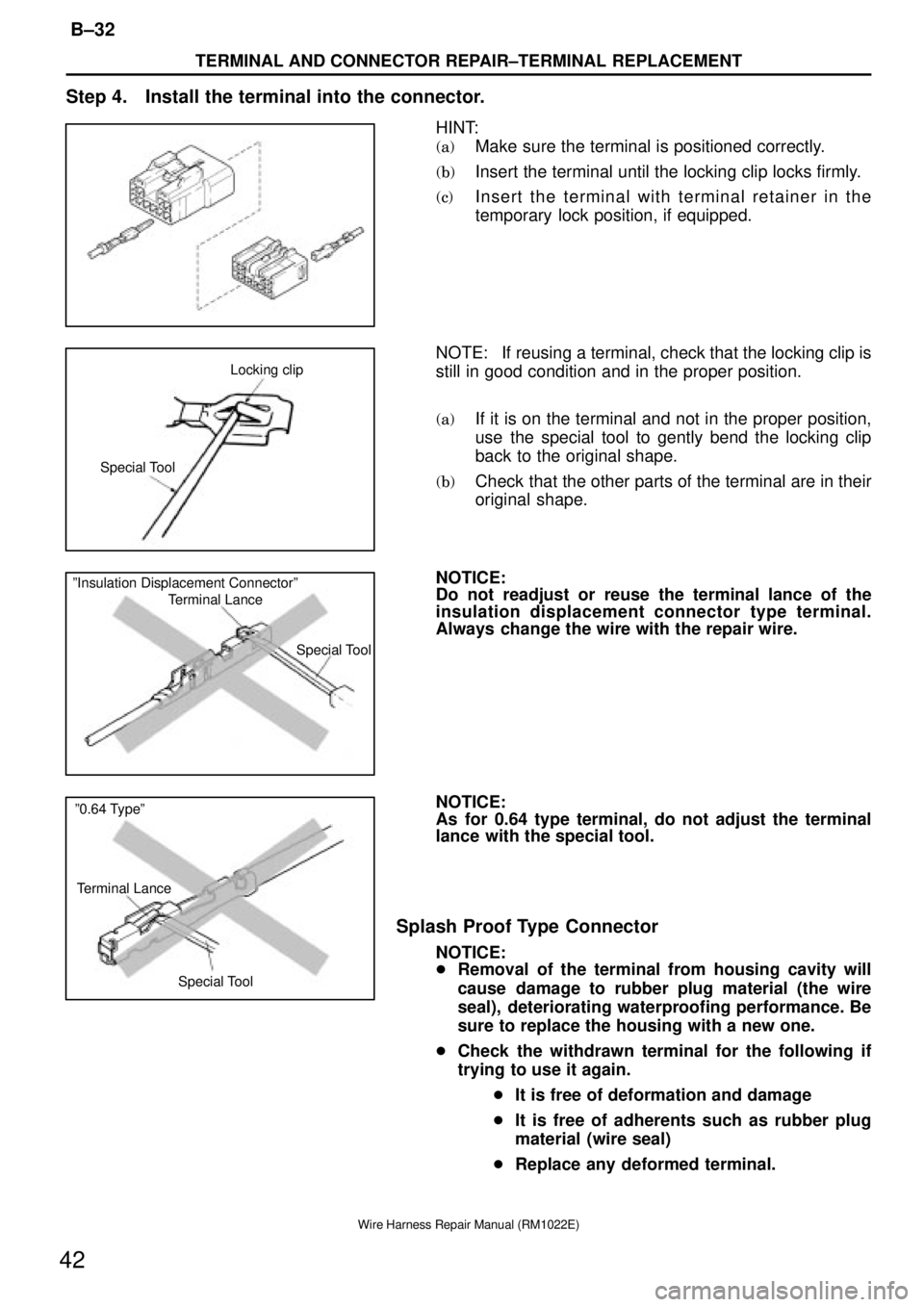
Special ToolLocking clip
Special Tool Terminal Lance ºInsulation Displacement Connectorº
Terminal Lance º0.64 Typeº
Special Tool
TERMINAL AND CONNECTOR REPAIR±TERMINAL REPLACEMENT
B±32
42
Wire Harness Repair Manual (RM1022E)
Step 4. Install the terminal into the connector.
HINT:
(a)Make sure the terminal is positioned correctly.
(b)Insert the terminal until the locking clip locks firmly.
(c)Insert the terminal with terminal retainer in the
temporary lock position, if equipped.
NOTE: If reusing a terminal, check that the locking clip is
still in good condition and in the proper position.
(a)If it is on the terminal and not in the proper position,
use the special tool to gently bend the locking clip
back to the original shape.
(b)Check that the other parts of the terminal are in their
original shape.
NOTICE:
Do not readjust or reuse the terminal lance of the
insulation displacement connector type terminal.
Always change the wire with the repair wire.
NOTICE:
As for 0.64 type terminal, do not adjust the terminal
lance with the special tool.
Splash Proof Type Connector
NOTICE:
�Removal of the terminal from housing cavity will
cause damage to rubber plug material (the wire
seal), deteriorating waterproofing performance. Be
sure to replace the housing with a new one.
�Check the withdrawn terminal for the following if
trying to use it again.
�It is free of deformation and damage
�It is free of adherents such as rubber plug
material (wire seal)
�Replace any deformed terminal.
Page 1476 of 2389
Lever
Lever
B±47
TERMINAL AND CONNECTOR REPAIR±HOW TO INSTALL AND REMOVE SPECIAL CONNECTORS
57
Wire Harness Repair Manual (RM1022E)
HOW TO INSTALL AND REMOVE SPECIAL CONNECTORS
Low Fit and Lever Type Connector
[Case 1]
1. Cut the connection of the connector
(1)Push the place indicated by the arrow.
(2)The lock is released and lever is lifted up.
(3)Lift the lever up until it stops.
an
(4)
Cut the connection of the connector.
NOTICE:
Do not hold the wire harness to pull it.
2. Connect the connector
(1)Connect the connector in the condition that the lever
is fully lifted up.
HINT: If the lever is locked at the lower position, follow
the procedure [Case 1]. (1) to (3) and lift the lever up fully.
Page 1478 of 2389
Lever
Lever is not locked
Lever
B±49
TERMINAL AND CONNECTOR REPAIR±HOW TO INSTALL AND REMOVE SPECIAL CONNECTORS
59
Wire Harness Repair Manual (RM1022E)
2. Connect the connector
(1)Connect the connector in the condition that the lever
is fully lifted up.
(2)Hold the connector to prevent it from slip off and push
it down until you hear a click to lock it.
(3)Confirm that the lever is securely locked.
[Case 3]
1. Cut the connection of the connector
(1)Pick the part indicated in the illustration by fingers.
(2)The lock is released and the lever is lifted up.
(3)Lift the lever up fully.
Page 1479 of 2389
Lever
Lever is not locked
TERMINAL AND CONNECTOR REPAIR±HOW TO INSTALL AND REMOVE SPECIAL CONNECTORS
B±50
60
Wire Harness Repair Manual (RM1022E)
(4)Cut the connection of the connector.
NOTICE:
Do not hold the wire harness to pull it.
2.Connect the connector
(1)Connect the connector in the condition that the lever
is fully lifted up.
HINT: If the lever is locked at the lower position, follow
the procedure [Case 3]. (1) to (3) and lift the lever up fully.
(2)Hold the connector to prevent it from slip off and push
it down until you hear a click to lock it.
(3)Confirm that the lever is securely fitted
Page 1837 of 2389
ELECTRONIC SPARK ADVANCE (ESA)
The ECU is programmed with data for optimum ignition timing
under any and all operating conditions. Using data provided
by sensors which monitor various engine functions (rpm, in-
take air volume, eng. temperature, etc.) the microcomputer
(ECU) triggers the spark at precisely the right instant.
IGNITION SYSTEM CIRCUIT
± IGNITION SYSTEMIgnition System CircuitIG±4
Page 1885 of 2389

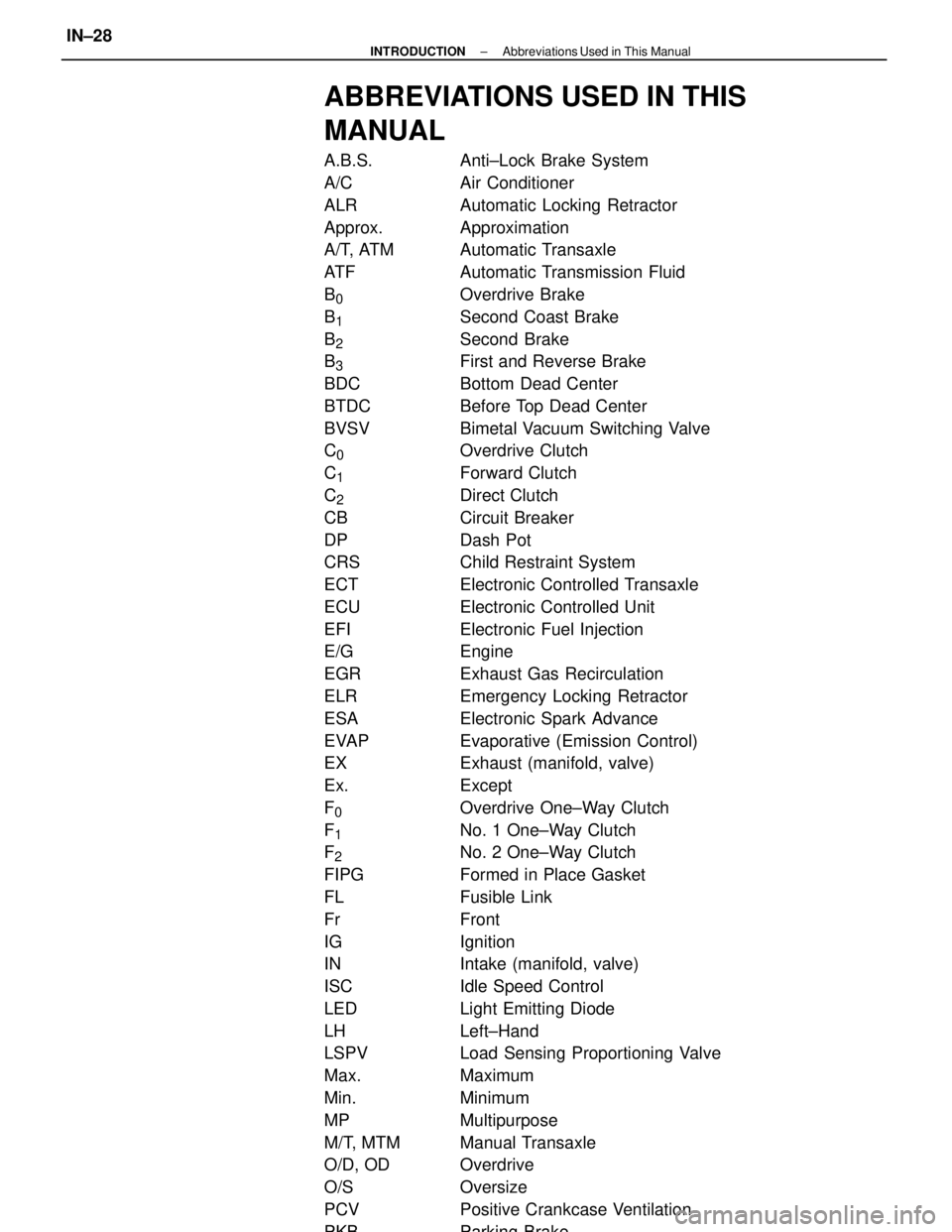
ABBREVIATIONS USED IN THIS
MANUAL
A.B.S. Anti±Lock Brake System
A/C Air Conditioner
ALR Automatic Locking Retractor
Approx. Approximation
A/T, ATM Automatic Transaxle
ATF Automatic Transmission Fluid
B
0 Overdrive Brake
B
1 Second Coast Brake
B
2 Second Brake
B
3 First and Reverse Brake
BDC Bottom Dead Center
BTDC Before Top Dead Center
BVSV Bimetal Vacuum Switching Valve
C
0 Overdrive Clutch
C
1 Forward Clutch
C
2 Direct Clutch
CB Circuit Breaker
DP Dash Pot
CRS Child Restraint System
ECT Electronic Controlled Transaxle
ECU Electronic Controlled Unit
EFI Electronic Fuel Injection
E/G Engine
EGR Exhaust Gas Recirculation
ELR Emergency Locking Retractor
ESA Electronic Spark Advance
EVAP Evaporative (Emission Control)
EX Exhaust (manifold, valve)
Ex. Except
F
0 Overdrive One±Way Clutch
F
1 No. 1 One±Way Clutch
F
2 No. 2 One±Way Clutch
FIPG Formed in Place Gasket
FL Fusible Link
Fr Front
IG Ignition
IN Intake (manifold, valve)
ISC Idle Speed Control
LED Light Emitting Diode
LH Left±Hand
LSPV Load Sensing Proportioning Valve
Max. Maximum
Min. Minimum
MP Multipurpose
M/T, MTM Manual Transaxle
O/D, OD Overdrive
O/S Oversize
PCV Positive Crankcase Ventilation
PKB Parking Brake
± INTRODUCTIONAbbreviations Used in This ManualIN±28
Page 1912 of 2389

Maintenance services indicated by a star (*) or asterisk (*) are required under the terms of the Emission Control Systems Warranty. See Owner's Guide or Warranty Booklet
for complete warranty information.
* For vehicles sold in California
* For vehicles sold outside California
(1) Applicable to vehicles operated under conditions of extensive idling and /or low speed driving for long distances such as police, taxi or door±to±door delivery use.
(2) Applicable when operating mainly on dusty roads. If not, follow SCHEDULE B.
(3) Includes inspection of fuel tank band and vapor vent system.
(4) Also applicable to lining drum for parking brake.
(5) Check for leakage.
(6) Check for oil leaks from steering gear housing.
(7) Applicable only when operating mainly on rough, muddy roads. The applicable parts are listed below. For other usage conditions, refer to SCHEDULE B.
w
Front and rear suspension member to body
w
0 Strut bar bracket to body bolts
w
Bolts for sheet installation
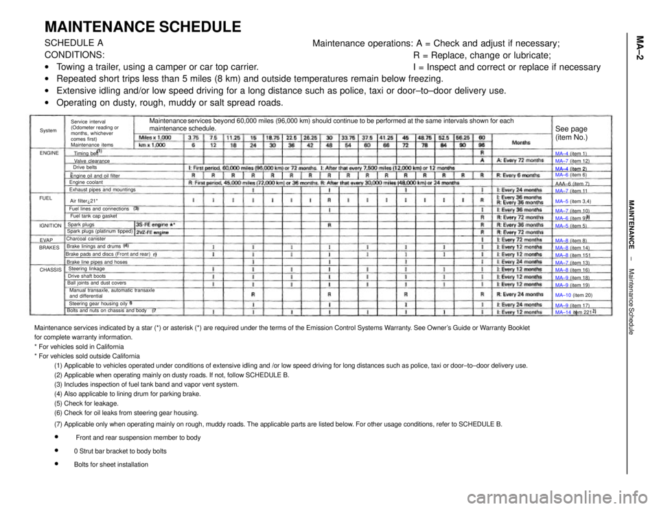
MAINTENANCE SCHEDULESCHEDULE A
CONDITIONS:
wTowing a trailer, using a camper or car top carrier.
wRepeated short trips less than 5 miles (8 km) and outside temperatures remain below freezing.
wExtensive idling and/or low speed driving for a long distance such as police, taxi or door±to±door delivery use.
wOperating on dusty, rough, muddy or salt spread roads.Maintenance operations: A = Check and adjust if necessary;
R = Replace, change or lubricate;
I = Inspect and correct or replace if necessary
Maintenance services beyond 60,000 miles (96,000 km) should continue to be performed at the same intervals shown for each
maintenance schedule.
Service interval
(Odometer reading or
months, whichever
comes first)
Maintenance items
Manual transaxle, automatic transaxle
and differential Brake pads and discs (Front and rear)
Bolts and nuts on chassis and bodyExhaust pipes and mountings
Steering gear housing oily Brake line pipes and hosesFuel lines and connections
Ball joints and dust coversEngine oil and oil filter
Spark plugs (platinum tipped)MA±4 (item 2)
MA±6 (item 6)
Brake linings and drumsFuel tank cap gasket
Drive shaft boots
MA±14 item 221 MA±10 (item 20) MA±5 (item 3,4)
Steering linkageMA±7 (item 12)
MA±8 (item 14) Valve clearance
MA±8 (item 16)
MA±9 (item 19) MA±7 (item 13) MA±7 (item 11
MA±7 (item 10)
MA±9 (item 18) Charcoal canister
MA±9 (item 17) MA±8 (item 151
See page
(item No.)
Engine coolant
MA±6 (item 9) MA±4 (item 1)
MA±4 (item 2)
MA±5 (item 5)
MA±8 (item 8) AAA±6 (item 7)
Air filter¿21*
Spark plugsTiming belt
Drive belts
IGNITION
CHASSIS BRAKESENGINESystem
EVAP FUEL
± MAINTENANCEMaintenance ScheduleMA±2