Page 751 of 2389

If the circuit has diodes, reverse the two leads and check
again.
When contacting the negative (±) lead to the diode positive
(+)
side and the positive (+) lead to the negative (±) side, there
should be continuity.
When contacting the two leads in reverse, there should be
no continuity.
HINT: Specifications may vary depending on the type of
tester, so refer to the tester's instruction manual before per-
forming the inspection.
Check LED (Light Emitting Diode) in the same manner as
that for diodes.
HINT:
wUse a tester with a power source of 3 V or greater to over-
come the circuit resistance.
wIf a suitable tester is not available, apply voltage and check
that the LED lights up.
CHECK FOR VOLTAGE
(a) Establish conditions in which voltage is present at
the check point.
Example:
(A) ± Ignition SW on
(B) ± Ignition SW and SW 1 on
(C) ± Ignition SW, SW 1, and Relay on (SW 2 off)
(b) Using a voltmeter, connect the negative (±) lead to
a good ground point or negative (±) battery terminal
and the positive (+) lead to the connector or compo-
nent terminal. This check can be done with a test
bulb instead of a voltmeter.
CHECK FOR CONTINUITY AND
RESISTANCE
(a) Disconnect the battery terminal or wire so there is
no voltage between the check points.
(b) Contact the two leads of an ohmmeter to each of
the check points.
± BODY ELECTRICAL SYSTEMGeneral InformationBE±5
Page 752 of 2389
CHECK FOR SHORT CIRCUIT
(a) Remove the blown fuse and eliminate all toads from
the fuse.
(b) Connect a test bulb in place of the fuse.
(e) Establish conditions in which the test bulb comes on.
Example:
(A) ± Ignition SW on
(B) ± Ignition SW and SW 1 on
(C) ± Ignition SW, SW 1 and Relay on (Connect the
Relay) and SW 2 oft (or Disconnect SW 2)
(d) Disconnect and reconnect the connectors while
watching the test bulb.
The short lies between the connector where the test
bulb stays lit and the connector where the bulb goes
out.
(e) Find the exact location of the short by lightly shaking
the problem wire along the body. (c) Use a volt/ohmmeter with high impedance (10 k
�/V
minimum) for troubleshooting of the electrical circuit.
± BODY ELECTRICAL SYSTEMGeneral InformationBE±6
Page 766 of 2389

Taillight Failure Sensor
INSPECTION OF SENSOR
1. INSPECT WARNING LIGHT OPERATION
(a) Disconnect the connector from the failure sensor and
ground the terminal 3 on the wire harness side.
(b) Remove the CHARGE fuse and turn the ignition
switch ON, check that the bulb lights.
If bulb does not light, inspect the bulb.
2. INSPECT SENSOR CIRCUIT
Disconnect the failure sensor connector and inspect the
connector on the wire harness side as shown in the chart.
If circuit is as specified, replace the relay.
Stop light switch ON (Brake pedal depressed)Stop light switch OFF (Brake pedal released)
Turn light control switch TAIL or HEAD Turn ignition switch to OFF or ACC Turn ignition switch to OFF or ACC
Turn light control switch OFF Turn ignition switch ON
Remove CHARGE fuse
Turn ignition
switch ON
Install CHARGE fuse
Tester
connectionSpecified value
Battery voltage
Battery voltage
Battery voltageBattery voltage
No voltage Continuity
No voltageContinuityNo vottage No voltage Continuity
ContinuityNo voltage
Continuity ContinuityConditionCheck for
Voltage Voltage
VoltageAlways
AlwaysAlways
± BODY ELECTRICAL SYSTEMLightingBE±20
Page 767 of 2389

Integration Relay
INSPECTION OF RELAY
INSPECT RELAY CIRCUIT
Disconnect the relay connector and inspect the connector
on the wire harness side as shown in the chart.
Passenger's side and rear door courtesy switches OFF
(Door closed)
Passenger's side or rear door courtesy switch ON
(Door opened)
Turn headlight dimmer switch to low beam or high beamDriver's side door courtesy switch ON (Door opened)Driver's side door courtesy switch OFF (Door closed)
Turn light control switch to OFF or TAIL
Turn light control switch TAIL or HEADTurn headlight dimmer switch to FlashTurn ignition switch to OFF or ACC
Turn light control switch to HEAD
Turn light control switch OFF
(w/o Fade Out System)
Turn ignition switch ON
Tester
connectionSpecified value
Battery voltageBattery voltageBattery voltage Battery voltage
Battery voltageNo continuity
No continuityNo continuity Condition
No voltageContinuity
No voltageNo voltage
ContinuityContinuityContinuity
Continuity
Continuity Check for
VoltageVoltage
Voltage
AlwaysAlways
± BODY ELECTRICAL SYSTEMLightingBE±21
Page 768 of 2389

Room Light Retainer Switch
INSPECTION OF SWITCH
INSPECT SWITCH CONTINUITY
(a) Check that there is no continuity between terminals
with the switch OFF (Door outside handle released).
(b) Check that there is continuity between terminals with
the switch ON (Door outside handle pulled).
If continuity is not as specified, replace the switch.
Passenger's side and rear door courtesy switches OFF
(Door closed)
Passenger's side or rear door courtesy switch ON
(Door opened)Door room light retainer switch ON
(Door outside handle pulled up on driver's side)
Door room light retainer switch OFF
(Door outside handle released on driver's side)
Turn headlight dimmer switch to low beam or high beamDriver's side door courtesy switch ON (Door opened) Driver's side door courtesy switch OFF (Door closed)
If circuit is as specified, replace the relay.
Turn light control switch to OFF or TAIL
Turn light control switch TAIL or HEADTurn headlight dimmer switch to FlashTurn ignition switch to OFF or ACC
Turn light control switch to HEAD
Turn light control switch OFF
(w/ Fade Out System)
Condition
Turn ignition switch ON Tester
connectionSpecified value
Battery voltage
Battery voltageBattery voltage
Battery voltageBattery voltage
Battery voltageNo continuity
No continuity
No continuityNo continuity
No voltage
No voltageNo voltage
ContinuityContinuity
Continuity ContinuityContinuity
Continuity Continuity
ContinuityContinuity Always . Check for
Voltage
VoltageVoltage
Voltage
Always
AlwaysAlways
± BODY ELECTRICAL SYSTEMLightingBE±22
Page 771 of 2389

(Relay Operation)
(a) Connect the positive (+) lead from the voltmeter to ter-
minal 7 and negative (±) lead to terminal 10.
(b) Check that there is battery voltage with light control
switch is turned on.
If operation is not as specified, replace the relay.If continuity is not as specified, replace the relay.
2. INSPECT DAYTIME RUNNING LIGHT RELAY
(Relay Circuit)
Disconnect the connector from the relay and inspect the
connector on the wire harness side as shown in the chart.
INSPECTION OF RELAY
1. INSPECT DIMMER RELAY (Continuity)
If circuit is as specified, inspect relay operation.
Apply battery voltage to
terminals 2 and 4.
Light control switch
position
Light control switch
position
Headlight dimmer
switch positionHeadlight dimmer
switch positionLow beam or High beam
Ignition switch
position 7 ± Ground
10 ± Ground
High beam or Flash 13 ± Ground
3 ± Ground
5 ± Ground
Tester connection
Ground terminal 5
Specified value
Battery voltageBattery voltageBattery voltage
Battery voltage Battery voltageNo continuity
No continuity TAIL or HEADNo continuity
No continuity
14 ± Ground12 ± GroundON or STARTLOCK or ACC
1 ± GroundOFF or TAIL
8 ± Ground2 ± Ground
6 ± Ground4 ± Ground
No voltage
No voltage
No voltageContinuity
Continuity Continuity
Continuity
ContinuityContinuity
Condition
Check for
Low beam Condition
Running
Terminal
Constant
Constant
Constant
Constant
Constant Voltage
EngineHEAD
Flash
StopOFF
± BODY ELECTRICAL SYSTEMLightingBE±25
Page 787 of 2389

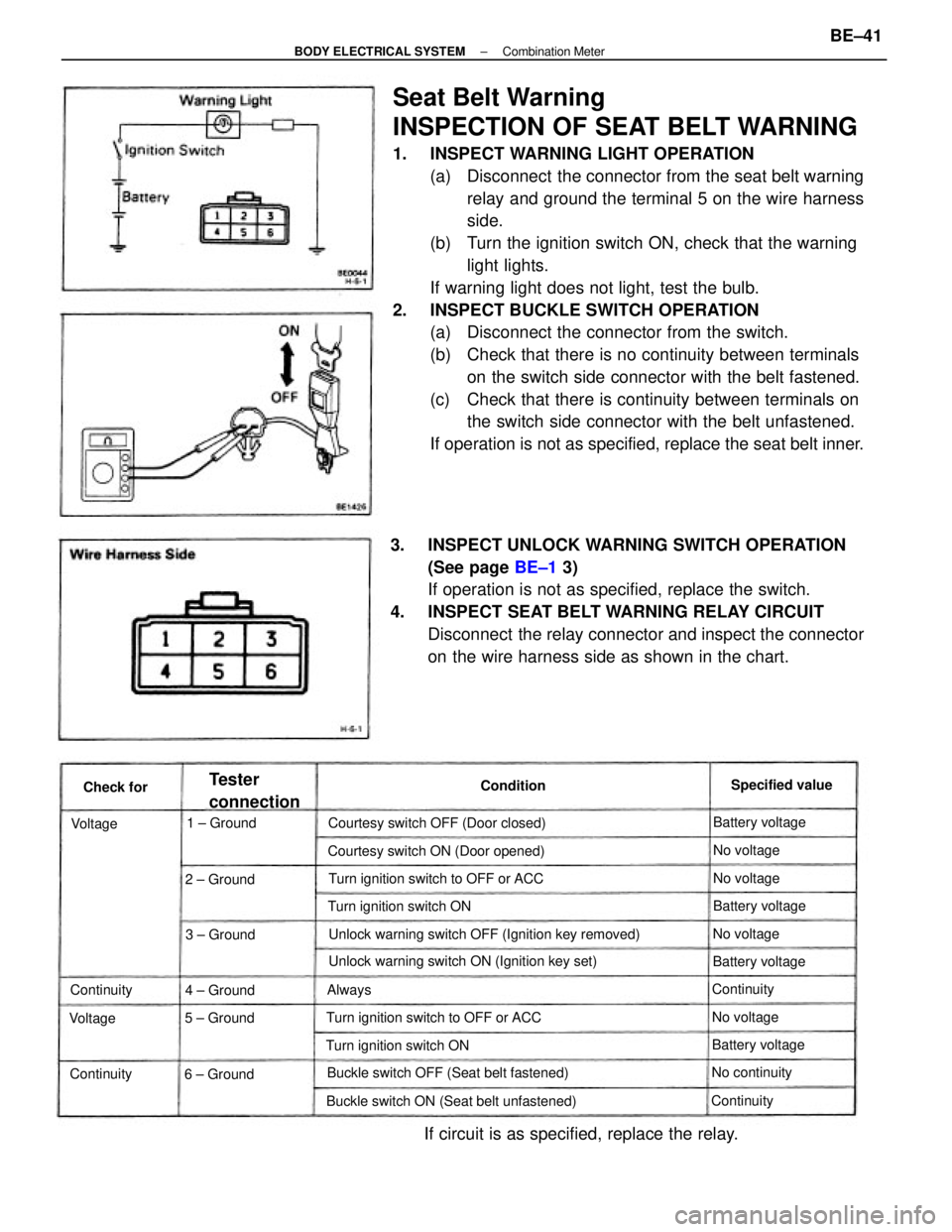
Seat Belt Warning
INSPECTION OF SEAT BELT WARNING
1. INSPECT WARNING LIGHT OPERATION
(a) Disconnect the connector from the seat belt warning
relay and ground the terminal 5 on the wire harness
side.
(b) Turn the ignition switch ON, check that the warning
light lights.
If warning light does not light, test the bulb.
2. INSPECT BUCKLE SWITCH OPERATION
(a) Disconnect the connector from the switch.
(b) Check that there is no continuity between terminals
on the switch side connector with the belt fastened.
(c) Check that there is continuity between terminals on
the switch side connector with the belt unfastened.
If operation is not as specified, replace the seat belt inner.
3. INSPECT UNLOCK WARNING SWITCH OPERATION
(See page BE±1 3)
If operation is not as specified, replace the switch.
4. INSPECT SEAT BELT WARNING RELAY CIRCUIT
Disconnect the relay connector and inspect the connector
on the wire harness side as shown in the chart.
Unlock warning switch OFF (Ignition key removed)
If circuit is as specified, replace the relay.
Unlock warning switch ON (Ignition key set)
Buckle switch ON (Seat belt unfastened)Buckle switch OFF (Seat belt fastened)Courtesy switch ON (Door opened)
Turn ignition switch to OFF or ACCTurn ignition switch to OFF or ACC Courtesy switch OFF (Door closed)
Turn ignition switch ONTurn ignition switch ON
6 ± Ground
Tester
connectionSpecified value
Battery voltage
Battery voltage
Battery voltageBattery voltage
No continuity 1 ± Ground
2 ± Ground
3 ± Ground
5 ± Ground4 ± GroundContinuity
Continuity
ContinuityNo voltageNo voltageNo voltage
No voltage
Continuity Condition
Check for
VoltageVoltage
Always
± BODY ELECTRICAL SYSTEMCombination MeterBE±41
Page 805 of 2389

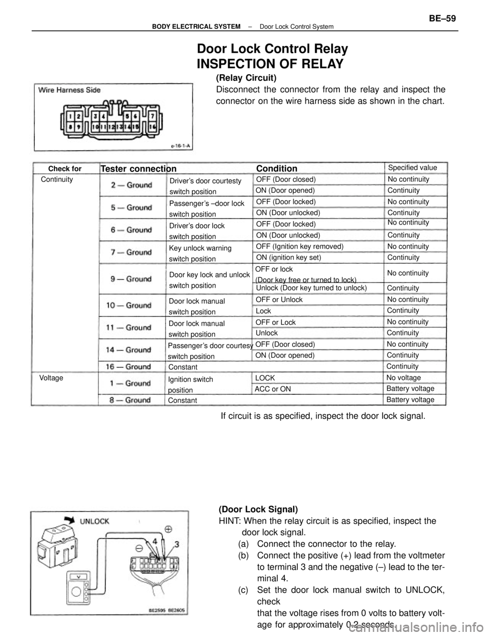
(Door Lock Signal)
HINT: When the relay circuit is as specified, inspect the
door lock signal.
(a) Connect the connector to the relay.
(b) Connect the positive (+) lead from the voltmeter
to terminal 3 and the negative (±) lead to the ter-
minal 4.
(c) Set the door lock manual switch to UNLOCK,
check
that the voltage rises from 0 volts to battery volt-
age for approximately 0.2 seconds.
Door Lock Control Relay
INSPECTION OF RELAY
(Relay Circuit)
Disconnect the connector from the relay and inspect the
connector on the wire harness side as shown in the chart.
If circuit is as specified, inspect the door lock signal.
OFF or lock
(Door key free or turned to lock)
Passenger's door courtesy
switch positionPassenger's ±door lock
switch positionDriver's door courtesty
switch position
Unlock (Door key turned to unlock) Door key lock and unlock
switch position Key unlock warning
switch positionOFF (Ignition key removed)
Door lock manual
switch position
Door lock manual
switch positionDriver's door lock
switch position
Ignition switch
positionON (ignition key set) ON (Door unlocked)
ON (Door unlocked) ON (Door opened)
Tester connection
OFF (Door locked)
ON (Door opened)OFF (Door locked)
OFF (Door closed)OFF (Door closed)Specified value
No continuity
Battery voltage Battery voltage OFF or UnlockNo continuity
No continuityNo continuity
No continuity
No continuity
No continuityNo continuity
Continuity OFF or Lock
No voltageContinuityContinuity
Continuity ContinuityContinuity
ContinuityContinuityContinuity
ACC or ON Continuity
ConditionCheck for
ConstantConstant
VoltageUnlock
LOCKLock
± BODY ELECTRICAL SYSTEMDoor Lock Control SystemBE±59