1985 FORD GRANADA battery location
[x] Cancel search: battery locationPage 197 of 255

Speed control module
Models before April 1992
9Refer to Section 27. The speed control
module shares the same mountings as the
AWS module; the AWS module is larger.
Models from April 1992
10The speed control module fitted to these
models is situated behind the glovebox on the
left-hand side of the facia. To gain access to
the module remove the left-hand facia
undercover panel. The speed control module
is vertically mounted just to the right of the
engine management module. Push the module
upwards to release the retaining clips then
lower it out from under the facia and
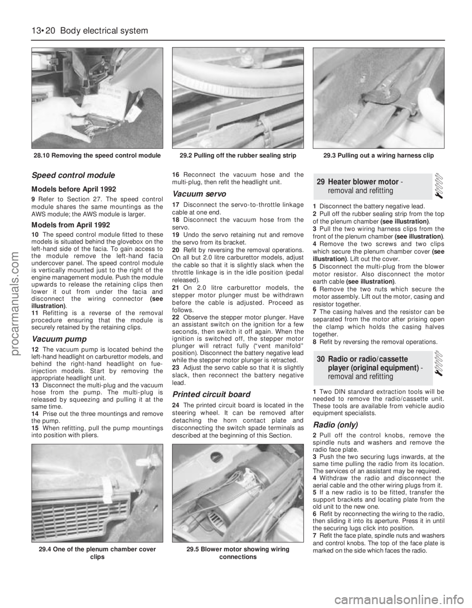
disconnect the wiring connector (see
illustration).
11Refitting is a reverse of the removal
procedure ensuring that the module is
securely retained by the retaining clips.
Vacuum pump
12The vacuum pump is located behind the
left-hand headlight on carburettor models, and
behind the right-hand headlight on fue-
injection models. Start by removing the
appropriate headlight unit.
13Disconnect the multi-plug and the vacuum
hose from the pump. The multi-plug is
released by squeezing and pulling it at the
same time.
14Prise out the three mountings and remove
the pump.
15When refitting, pull the pump mountings
into position with pliers. 16Reconnect the vacuum hose and the
multi-plug, then refit the headlight unit.
Vacuum servo
17Disconnect the servo-to-throttle linkage
cable at one end.
18Disconnect the vacuum hose from the
servo.
19Undo the servo retaining nut and remove
the servo from its bracket.
20Refit by reversing the removal operations.
On all but 2.0 litre carburettor models, adjust
the cable so that it is slightly slack when the
throttle linkage is in the idle position (pedal
released).
21On 2.0 litre carburettor models, the
stepper motor plunger must be withdrawn
before the cable is adjusted. Proceed as
follows.
22Observe the stepper motor plunger. Have
an assistant switch on the ignition for a few
seconds, then switch it off again. When the
ignition is switched off, the stepper motor
plunger will retract fully (“vent manifold”
position). Disconnect the battery negative lead
while the stepper motor plunger is retracted.
23Adjust the servo cable so that it is slightly
slack, then reconnect the battery negative
lead.
Printed circuit board
24The printed circuit board is located in the
steering wheel. It can be removed after
detaching the horn contact plate and
disconnecting the switch spade terminals as
described at the beginning of this Section.1Disconnect the battery negative lead.
2Pull off the rubber sealing strip from the top
of the plenum chamber (see illustration).
3Pull the two wiring harness clips from the
front of the plenum chamber (see illustration).
4Remove the two screws and two clips
which secure the plenum chamber cover (see
illustration). Lift out the cover.
5Disconnect the multi-plug from the blower
motor resistor. Also disconnect the motor
earth cable (see illustration).
6Remove the two nuts which secure the
motor assembly. Lift out the motor, casing and
resistor together.
7The casing halves and the resistor can be
separated from the motor after prising open
the clamp which holds the casing halves
together.
8Refit by reversing the removal operations.
1Two DIN standard extraction tools will be
needed to remove the radio/cassette unit.
These tools are available from vehicle audio
equipment specialists.
Radio (only)
2Pull off the control knobs, remove the
spindle nuts and washers and remove the
radio face plate.
3Push the two securing lugs inwards, at the
same time pulling the radio from its location.
The services of an assistant may be required.
4Withdraw the radio and disconnect the
aerial cable and the other wiring plugs from it.
5If a new radio is to be fitted, transfer the
support brackets and locating plate from the
old unit to the new one.
6Refit by reconnecting the wiring to the radio,
then sliding it into its aperture. Press it in until
the securing lugs click into position.
7Refit the face plate, spindle nuts and washers
and control knobs. The top of the face plate is
marked on the side which faces the radio.
30Radio or radio/cassette
player (original equipment) -
removal and refitting
29Heater blower motor -
removal and refitting
13•20Body electrical system
28.10 Removing the speed control module
29.4 One of the plenum chamber cover
clips29.5 Blower motor showing wiring
connections
29.2 Pulling off the rubber sealing strip29.3 Pulling out a wiring harness clip
procarmanuals.com
Page 200 of 255

The components of the alarm system are a
control module, tripping switches, activating
switches, an alarm horn and a signal buzzer.
The control module is located behind the
facia. It determines whether the alarm is set or
not, monitors the tripping switches and the
ignition circuit, and limits the duration of the
alarm to 30 seconds. This last item is a legal
requirement. The control module also
operates the signal buzzer to tell the driver
that the alarm is set, and controls the activator
delay.
The tripping switches on the doors and
tailgate are the same as those used for “open
door” warnings in the AWS. The bonnet switch
is peculiar to the alarm system.
The activating switches are fitted to the
front door lock barrels, where they are
activated by a lug on the end of the barrel.
They only make contact momentarily as the
lock is operated.
The alarm horn is mounted next to the
battery. Both the horn and its leads are
claimed to be inaccessible without opening
the bonnet. The signal buzzer is also mounted
under the bonnet.
No service, repair or component renewal
procedures have been published for the alarmsystem components on earlier models. Any
problems arising which cannot be dealt with
by component substitution should therefore
be referred to a Ford dealer.
Ultrasonic sensor
1Disconnect the battery negative terminal.
2Prise out the retaining screw trim cap from
the centre of the sensor then slacken and
remove the retaining screws and lower the
sensor away from the headlining,
disconnecting the wiring plug as it becomes
accessible.
3Refitting is the reverse of the removal
procedure.
Anti-theft alarm module (models
from April 1992)
4On these models the alarm module is located
behind the righthand lower facia panel.
5To remove the module, remove the right-
hand facia undercover and lower facia panel.
6The anti-theft alarm module is the left-hand
of the two modules situated directly above the
control pedals. Release the module retaining
clips then disconnect the wiring connector and
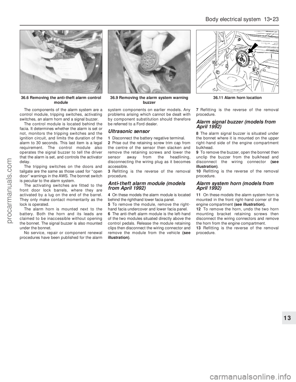
remove the module from the vehicle (see
illustration).7Refitting is the reverse of the removal
procedure.
Alarm signal buzzer (models from
April 1992)
8The alarm signal buzzer is situated under
the bonnet where it is mounted on the upper
right-hand side of the engine compartment
bulkhead.
9To remove the buzzer, open the bonnet then
unclip the buzzer from the bulkhead and
disconnect the wiring connector (see
illustration).
10Refitting is the reverse of the removal
procedure.
Alarm system horn (models from
April 1992)
11On these models the alarm system horn is
mounted in the front right-hand corner of the
engine compartment (see illustration).
12To remove the horn, undo the two horn
mounting bracket retaining screws then
disconnect the wiring connectors and remove
the horn from the engine compartment.
13Refitting is the reverse of the removal
procedure.
Body electrical system 13•23
13
36.6 Removing the anti-theft alarm control
module36.9 Removing the alarm system warning
buzzer36.11 Alarm horn location
procarmanuals.com
Page 249 of 255

REF•14Glossary of Technical Terms
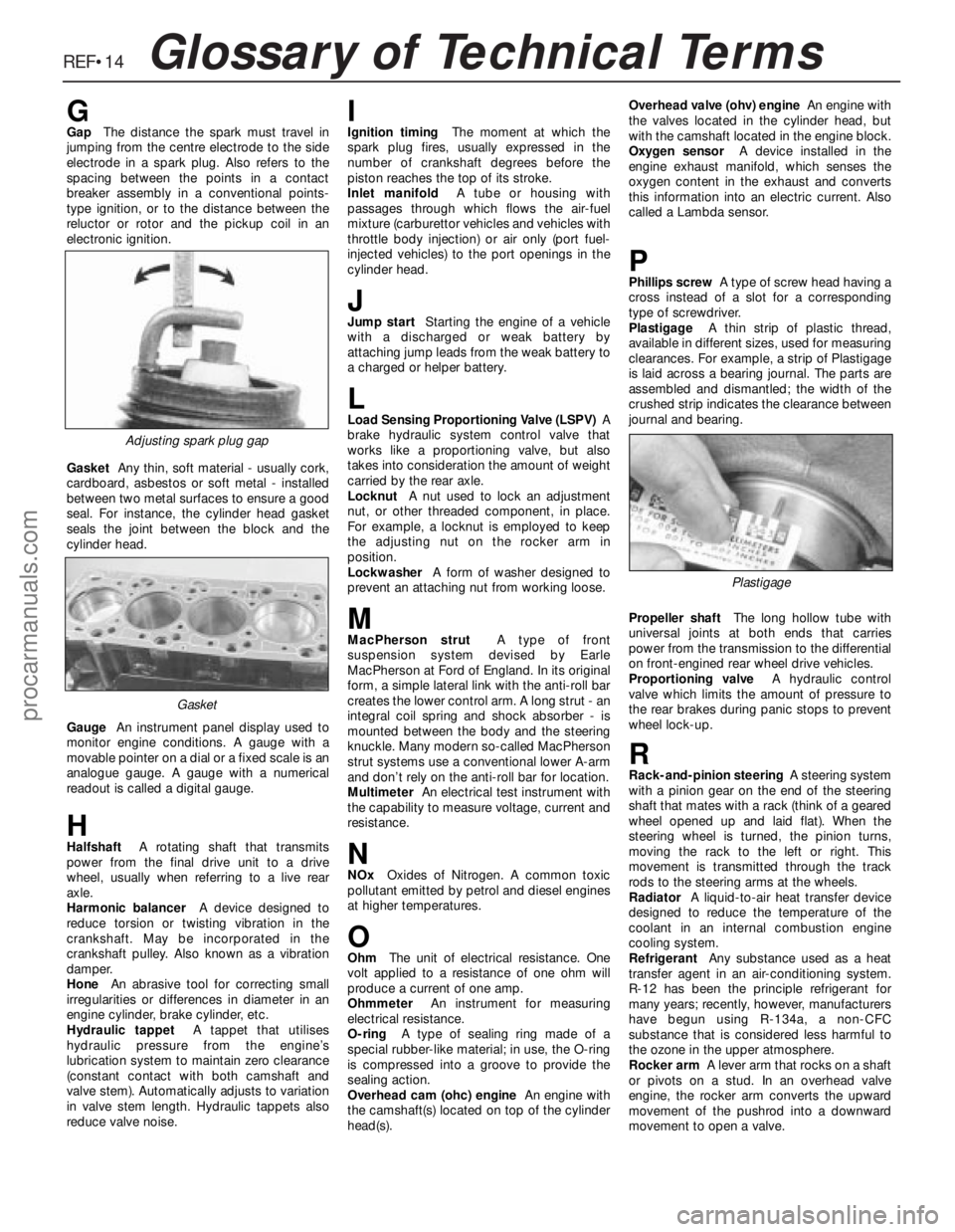
GGapThe distance the spark must travel in
jumping from the centre electrode to the side
electrode in a spark plug. Also refers to the
spacing between the points in a contact
breaker assembly in a conventional points-
type ignition, or to the distance between the
reluctor or rotor and the pickup coil in an
electronic ignition.
GasketAny thin, soft material - usually cork,
cardboard, asbestos or soft metal - installed
between two metal surfaces to ensure a good
seal. For instance, the cylinder head gasket
seals the joint between the block and the
cylinder head.
GaugeAn instrument panel display used to
monitor engine conditions. A gauge with a
movable pointer on a dial or a fixed scale is an
analogue gauge. A gauge with a numerical
readout is called a digital gauge.
HHalfshaftA rotating shaft that transmits
power from the final drive unit to a drive
wheel, usually when referring to a live rear
axle.
Harmonic balancerA device designed to
reduce torsion or twisting vibration in the
crankshaft. May be incorporated in the
crankshaft pulley. Also known as a vibration
damper.
HoneAn abrasive tool for correcting small
irregularities or differences in diameter in an
engine cylinder, brake cylinder, etc.
Hydraulic tappetA tappet that utilises
hydraulic pressure from the engine’s
lubrication system to maintain zero clearance
(constant contact with both camshaft and
valve stem). Automatically adjusts to variation
in valve stem length. Hydraulic tappets also
reduce valve noise.
IIgnition timingThe moment at which the
spark plug fires, usually expressed in the
number of crankshaft degrees before the
piston reaches the top of its stroke.
Inlet manifoldA tube or housing with
passages through which flows the air-fuel
mixture (carburettor vehicles and vehicles with
throttle body injection) or air only (port fuel-
injected vehicles) to the port openings in the
cylinder head.
JJump startStarting the engine of a vehicle
with a discharged or weak battery by
attaching jump leads from the weak battery to
a charged or helper battery.
LLoad Sensing Proportioning Valve (LSPV)A
brake hydraulic system control valve that
works like a proportioning valve, but also
takes into consideration the amount of weight
carried by the rear axle.
LocknutA nut used to lock an adjustment
nut, or other threaded component, in place.
For example, a locknut is employed to keep
the adjusting nut on the rocker arm in
position.
LockwasherA form of washer designed to
prevent an attaching nut from working loose.
MMacPherson strutA type of front
suspension system devised by Earle
MacPherson at Ford of England. In its original
form, a simple lateral link with the anti-roll bar
creates the lower control arm. A long strut - an
integral coil spring and shock absorber - is
mounted between the body and the steering
knuckle. Many modern so-called MacPherson
strut systems use a conventional lower A-arm
and don’t rely on the anti-roll bar for location.
MultimeterAn electrical test instrument with
the capability to measure voltage, current and
resistance.
NNOxOxides of Nitrogen. A common toxic
pollutant emitted by petrol and diesel engines
at higher temperatures.
OOhmThe unit of electrical resistance. One
volt applied to a resistance of one ohm will
produce a current of one amp.
OhmmeterAn instrument for measuring
electrical resistance.
O-ringA type of sealing ring made of a
special rubber-like material; in use, the O-ring
is compressed into a groove to provide the
sealing action.
Overhead cam (ohc) engineAn engine with
the camshaft(s) located on top of the cylinder
head(s).Overhead valve (ohv) engineAn engine with
the valves located in the cylinder head, but
with the camshaft located in the engine block.
Oxygen sensorA device installed in the
engine exhaust manifold, which senses the
oxygen content in the exhaust and converts
this information into an electric current. Also
called a Lambda sensor.
PPhillips screwA type of screw head having a
cross instead of a slot for a corresponding
type of screwdriver.
PlastigageA thin strip of plastic thread,
available in different sizes, used for measuring
clearances. For example, a strip of Plastigage
is laid across a bearing journal. The parts are
assembled and dismantled; the width of the
crushed strip indicates the clearance between
journal and bearing.
Propeller shaftThe long hollow tube with
universal joints at both ends that carries
power from the transmission to the differential
on front-engined rear wheel drive vehicles.
Proportioning valveA hydraulic control
valve which limits the amount of pressure to
the rear brakes during panic stops to prevent
wheel lock-up.
RRack-and-pinion steeringA steering system
with a pinion gear on the end of the steering
shaft that mates with a rack (think of a geared
wheel opened up and laid flat). When the
steering wheel is turned, the pinion turns,
moving the rack to the left or right. This
movement is transmitted through the track
rods to the steering arms at the wheels.
RadiatorA liquid-to-air heat transfer device
designed to reduce the temperature of the
coolant in an internal combustion engine
cooling system.
RefrigerantAny substance used as a heat
transfer agent in an air-conditioning system.
R-12 has been the principle refrigerant for
many years; recently, however, manufacturers
have begun using R-134a, a non-CFC
substance that is considered less harmful to
the ozone in the upper atmosphere.
Rocker armA lever arm that rocks on a shaft
or pivots on a stud. In an overhead valve
engine, the rocker arm converts the upward
movement of the pushrod into a downward
movement to open a valve.
Adjusting spark plug gap
Plastigage
Gasket
procarmanuals.com