1985 FORD GRANADA engine coolant
[x] Cancel search: engine coolantPage 87 of 255
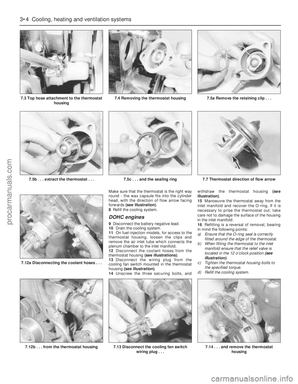
Make sure that the thermostat is the right way
round - the wax capsule fits into the cylinder
head, with the direction of flow arrow facing
forwards (see illustration).
8Refill the cooling system.
DOHC engines
9Disconnect the battery negative lead.
10Drain the cooling system.
11On fuel-injection models, for access to the
thermostat housing, loosen the clips and
remove the air inlet tube which connects the
plenum chamber to the inlet manifold.
12Disconnect the coolant hoses from the
thermostat housing (see illustrations).
13Disconnect the wiring plug from the
cooling fan switch mounted in the thermostat
housing (see illustration).
14Unscrew the three securing bolts, andwithdraw the thermostat housing (see
illustration).
15Manoeuvre the thermostat away from the
inlet manifold and recover the O-ring. If it is
necessary to prise the thermostat out, take
care not to damage the surface of the housing
in the inlet manifold.
16Refitting is a reversal of removal, bearing
in mind the following points:
a)Ensure that the O-ring seal is correctly
fitted around the edge of the thermostat.
b)When fitting the thermostat to the inlet
manifold ensure that the relief valve is
located in the 12 o’clock position (see
illustration).
c)Tighten the thermostat housing bolts to
the specified torque.
d)Refill the cooling system.
3•4Cooling, heating and ventilation systems
7.3 Top hose attachment to the thermostat
housing
7.12b . . . from the thermostat housing
7.5b . . . extract the thermostat . . .7.5c . . . and the sealing ring7.7 Thermostat direction of flow arrow
7.12a Disconnecting the coolant hoses . . .
7.13 Disconnect the cooling fan switch
wiring plug . . .7.14 . . . and remove the thermostat
housing
7.4 Removing the thermostat housing7.5a Remove the retaining clip . . .
procarmanuals.com
Page 89 of 255
7Remove the three securing bolts and
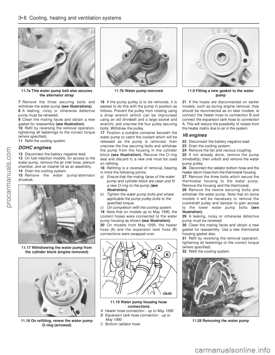
withdraw the water pump (see illustrations).
8A leaking, noisy or otherwise defective
pump must be renewed.
9Clean the mating faces and obtain a new
gasket for reassembly (see illustration).
10Refit by reversing the removal operation,
tightening all fastenings to the correct torque
(where specified).
11Refill the cooling system.
DOHC engines
12Disconnect the battery negative lead.
13On fuel-injection models, for access to the
water pump, remove the air inlet hose, plenum
chamber, and air cleaner lid as an assembly.
14Drain the cooling system.
15Remove the water pump/alternator
drivebelt.16If the pump pulley is to be removed, it is
easiest to do this with the pump in position as
follows. Prevent the pulley from rotating using
a strap wrench (which can be improvised
using an old drivebelt and a large socket and
wrench), and unscrew the four pulley securing
bolts. Withdraw the pulley.
17Position a suitable container beneath the
water pump to catch the coolant which will be
released as the pump is removed, then
unscrew the five securing bolts and withdraw
the pump from the housing in the cylinder
block (see illustration). Recover the O-ring
seal and discard it; a new one must be used
on refitting.
18Refitting is a reversal of removal, bearing
in mind the following points:
a)Ensure that the mating faces of the water
pump and cylinder block are clean and fit
a new O-ring to the pump (see
illustration).
b)Tighten the water pump bolts and where
applicable the pump pulley bolts to the
specified torque.
c)On completion refill the cooling system.
19Note that on models up to May 1990, the
coolant hoses were connected to the water
pump housing as shown(see illustration).
20On models from May 1990, the heater
hose (A) and the expansion tank hose (B)
connections were swapped over.21If the hoses are disconnected on earlier
models, such as during engine removal, they
should be reconnected as on later models, ie
connect the heater hose to connection B and
connect the expansion tank hose to connection
A. This will reduce the possibility of noises from
the heater matrix due to air in the system.
V6 engines
22Disconnect the battery negative lead.
23Drain the cooling system.
24Remove the fan and viscous coupling.
25If not already done, remove the pump
drivebelt(s), then unbolt and remove the water
pump pulley.
26Disconnect the radiator bottom hose and the
heater return hose from the thermostat housing.
27Remove the three bolts which secure the
thermostat housing to the water pump.
Remove the housing and the thermostat.
28Remove the twelve securing bolts and
withdraw the water pump. Note that on some
models it will be necessary to remove the
crankshaft pulley and damper to gain access
to the lower water pump bolts (see
illustration).
29A leaking, noisy or otherwise defective
pump must be renewed.
30Clean the mating faces and obtain a new
gasket for reassembly. Use a new thermostat
housing gasket also.
31Refit by reversing the removal operation,
tightening all fastenings to the correct torque
(where specified).
32Refill the cooling system.
3•6Cooling, heating and ventilation systems
11.7a This water pump bolt also secures
the alternator strap
11.18 On refitting, renew the water pump
O-ring (arrowed)
11.17 Withdrawing the water pump from
the cylinder block (engine removed)
11.19 Water pump housing hose
connections
A Heater hose connection - up to May 1990
B Expansion tank hose connection - up to
May 1990
C Bottom radiator hose
11.28 Removing the water pump
11.7b Water pump removed11.9 Fitting a new gasket to the water
pump
procarmanuals.com
Page 90 of 255
See Chapter 1, Section 21.
1On 2.0 litre DOHC engines only, remove the
water pump/alternator drivebelt as described
in the previous Section.
2Loosen the alternator lower mounting
through-bolt, then remove the alternator upper
mounting bolt, and swing the alternator away
from the engine.
3Unscrew the central securing bolt, and
withdraw the drivebelt tensioner assembly.
4Commence refitting by positioning the
tensioner on the cylinder block, ensuring that
the lug on the rear of the tensioner bracket
engages with the corresponding hole in the
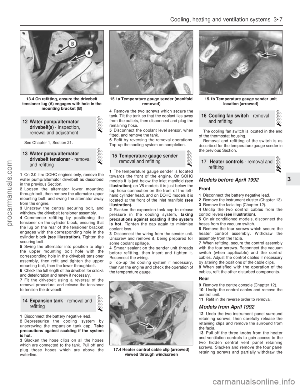
cylinder block (see illustration). Tighten the
securing bolt.
5Swing the alternator into position to align
the upper mounting bolt hole with the
corresponding hole in the drivebelt tensioner
assembly, then refit and tighten the upper
mounting bolt, then the lower throughbolt.
6Check the full length of the drivebelt for cracks
and deterioration and renew if necessary.
7Fit the drivebelt using a reversal of the
removal procedure, and release the tensioner
to tension the drivebelt.
1Disconnect the battery negative lead.
2Depressurize the cooling system by
unscrewing the expansion tank cap. Take
precautions against scalding if the system
is hot.
3Slacken the hose clips on all the hoses
which are connected to the tank. Pull off and
plug those hoses which are above the
waterline.4Remove the two screws which secure the
tank. Tilt the tank so that the coolant lies away
from the outlets, then disconnect and plug the
remaining hose.
5Disconnect the coolant level sensor, when
fitted, and remove the tank.
6Refit by reversing the removal operations.
Top-up the cooling system on completion.
1The temperature gauge sender is located
towards the front of the engine. On SOHC
models it is just below the inlet manifold (see
illustration); on V6 models it is just below the
top hose connection on the front of the left-
hand cylinder head, and on DOHC models it is
located at the front of the inlet manifold (see
illustration).
2Slacken the expansion tank cap to release
pressure in the cooling system, taking
precautions against scalding if the system
is hot.Tighten the cap again to minimise
coolant loss.
3Disconnect the wiring from the sender unit.
Unscrew and remove it, being prepared for
some coolant spillage.
4Smear sealant on the sender unit threads
before refitting, then insert and tighten it.
Reconnect the wiring.
5Top-up the cooling system if necessary,
then run the engine and check the operation of
the temperature gauge.The cooling fan switch is located in the end
of the thermostat housing.
Removal and refitting of the switch is as
described for the temperature gauge sender in
the previous Section.
Models before April 1992
Front
1Disconnect the battery negative lead.
2Remove the instrument cluster (Chapter 13).
3Remove the facia top (Chapter 12).
4Unclip the two control cables from the
control levers (see illustration).
5On air conditioned models, disconnect the
hoses from the vacuum switch.
6Remove the four screws which secure the
heater control assembly. Withdraw the
assembly from the facia.
7When refitting, secure the control assembly
with the four screws. Reconnect the vacuum
switch (when applicable) and the control
cables. Adjust the control cables if necessary
by altering the positions of the cable clips.
8When satisfied with the operation of the
cables, refit the other disturbed components.
Rear
9Remove the centre console (Chapter 12).
10Unclip the control cables and remove the
control unit.
11Refit in the reverse order to removal.
Models from April 1992
12Undo the two instrument panel surround
retaining screws, then carefully release the
retaining clips and remove the surround from
the facia.
13Pull off the three knobs from the heater
and ventilation controls to gain access to the
two hidden central vent panel retaining
screws. Slacken and remove the four panel
retaining screws and partially withdraw the
17Heater controls - removal and
refitting
16Cooling fan switch - removal
and refitting
15Temperature gauge sender -
removal and refitting
14Expansion tank - removal and
refitting
13Water pump/alternator
drivebelt tensioner - removal
and refitting
12Water pump/alternator
drivebelt(s) - inspection,
renewal and adjustment
Cooling, heating and ventilation systems 3•7
3
13.4 On refitting, ensure the drivebelt
tensioner lug (A) engages with hole in the
mounting bracket (B)15.1a Temperature gauge sender (manifold
removed)15.1b Temperature gauge sender unit
location (arrowed)
17.4 Heater control cable clip (arrowed)
viewed through windscreen
procarmanuals.com
Page 91 of 255
panel. Disconnect the wiring connectors from
the heated window switches and fuel
computer (where fitted) and remove the panel
from the car.
14Undo the two retaining screws then
manoeuvre the control panel out of the facia
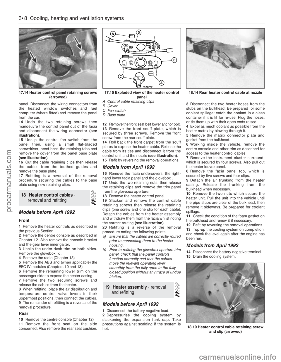
and disconnect the wiring connector (see
illustration).
15Unclip the central fan switch from the
panel then, using a small flat-bladed
screwdriver, bend back the retaining tabs and
remove the cover from the panel base plate
(see illustration).
16Cut the cable retaining clips then release
the cables from the toothed guides and
remove the base plate.
17Refitting is a reversal of the removal
procedure securing the cables to the base
plate using new retaining clips.
Models before April 1992
Front
1Remove the heater controls as described in
the previous Section.
2Remove the centre console as described in
Chapter 12. Also remove the console bracket
and the gear lever inner gaiter.
3Unclip the under-dash trim on both sides.
Remove the glovebox lid.
4Remove the radio (Chapter 13).
5Remove the ABS and (when applicable) the
EEC IV modules (Chapters 10 and 13).
6Remove the remaining lower trim on the
passenger side to expose the heater casing.
7Remove the two securing screws and
release the cables from the heater.
8When refitting, place the air distribution and
temperature control valve levers in their
uppermost positions, then connect the cables.
9The remainder of refitting is a reversal of the
removal procedure.
Rear
10Remove the centre console (Chapter 12).
11Remove the front seat on the side
concerned. Also remove the rear seat cushion. 12Remove the front seat belt lower anchor bolt.
13Remove the front scuff plate, which is
secured by three screws. Remove the front
screw from the rear scuff plate.
14Roll back the front carpet from the scuff
plates to expose the heater cable. Release the
cable from its ties and disconnect it from the
control unit and the nozzle (see illustration).
15Refit by reversing the removal operations.
Models from April 1992
16Remove the facia undercovers, the right-
hand lower facia panel and the glovebox .
17Undo the two retaining nuts, then release
the retaining clips and remove the trim panel
from the glovebox aperture.
18Remove the heater control panel.
19Slacken and remove the control cable
retaining screws then release the retaining
clips (one screw and one clip for each cable).
Detach the cables from the heater assembly
and withdraw them from the facia whilst noting
the correct routing (see illustration).
20Refitting is a reverse of the removal
procedure noting the following points.
a)Ensure that the cables are correctly routed
prior to connecting them to the heater
housing.
b)Prior to refitting the glovebox aperture trim
panel, check that the panel controls
function correctly and that the cables
move the relevant operating lever
smoothly from the fully open to the fully
closed position without any trace of undue
friction.
Models before April 1992
1Disconnect the battery negative lead.
2Depressurise the cooling system by
slackening the expansion tank cap. Take
precautions against scalding if the system is
hot.3Disconnect the two heater hoses from the
stubs on the bulkhead. Be prepared for some
coolant spillage: catch the coolant in a clean
container if it is fit for re-use. Plug the hoses,
or tie them up with their open ends raised.
4Expel as much coolant as possible from the
heater matrix by blowing through it.
5Remove the matrix connector plate and
gasket from the bulkhead.
6Working inside the vehicle, remove the
centre console and other trim as described for
access to the heater control cables .
7Remove the instrument cluster surround,
which is secured by four screws. Also pull out
the heater louvre panel.
8Remove the facia panel top, which is
secured by five screws and four clips.
9Detach the air trunking from the heater
casing. Release the trunking from the
bulkhead when necessary.
10Remove the two nuts which secure the
heater unit. Pull the unit into the vehicle until
the pipe stubs are clear of the bulkhead, then
remove it sideways. Be prepared for coolant
spillage.
11Check the condition of the foam gasket on
the bulkhead and renew it if necessary.
12Refit by reversing the removal operations.
13Top-up the cooling system on completion,
and check the level again after the engine has
been run.
Models from April 1992
14Disconnect the battery negative terminal.
15Drain the cooling system.
19Heater assembly - removal
and refitting
18Heater control cables -
removal and refitting
3•8Cooling, heating and ventilation systems
17.14 Heater control panel retaining screws
(arrowed)
18.19 Heater control cable retaining screw
and clip (arrowed)
17.15 Exploded view of the heater control
panel
A Control cable retaining clips
B Cover
C Fan switch
D Base plate18.14 Rear heater control cable at nozzle
procarmanuals.com
Page 92 of 255
16Locate the heater matrix feed and return
hoses on the engine compartment bulkhead.
Slacken the retaining clips and disconnect
both hoses from the matrix unions. Be
prepared for some coolant spillage. Plug the
matrix unions to prevent residual coolant
being spilt as the assembly is removed.
17Slacken and remove the two retaining
screws then remove the matrix cover plate
and gasket from the bulkhead; discard the
gasket as a new one should be used on
refitting.
18Remove the facia panel.
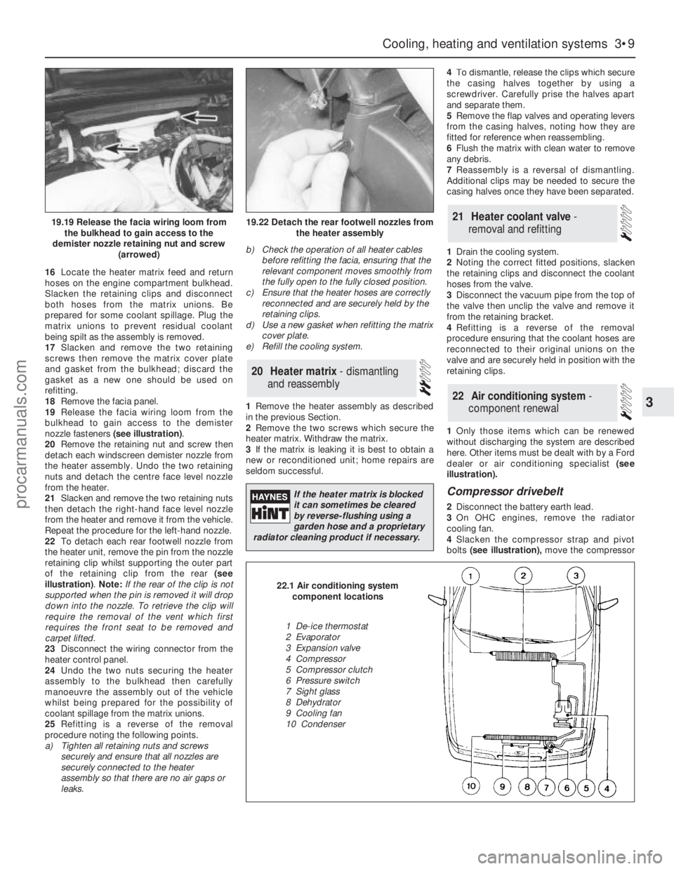
19Release the facia wiring loom from the
bulkhead to gain access to the demister
nozzle fasteners (see illustration).
20Remove the retaining nut and screw then
detach each windscreen demister nozzle from
the heater assembly. Undo the two retaining
nuts and detach the centre face level nozzle
from the heater.
21Slacken and remove the two retaining nuts
then detach the right-hand face level nozzle
from the heater and remove it from the vehicle.
Repeat the procedure for the left-hand nozzle.
22To detach each rear footwell nozzle from
the heater unit, remove the pin from the nozzle
retaining clip whilst supporting the outer part
of the retaining clip from the rear (see
illustration). Note: If the rear of the clip is not
supported when the pin is removed it will drop
down into the nozzle. To retrieve the clip will
require the removal of the vent which first
requires the front seat to be removed and
carpet lifted.
23Disconnect the wiring connector from the
heater control panel.
24Undo the two nuts securing the heater
assembly to the bulkhead then carefully
manoeuvre the assembly out of the vehicle
whilst being prepared for the possibility of
coolant spillage from the matrix unions.
25Refitting is a reverse of the removal
procedure noting the following points.
a)Tighten all retaining nuts and screws
securely and ensure that all nozzles are
securely connected to the heater
assembly so that there are no air gaps or
leaks.b)Check the operation of all heater cables
before refitting the facia, ensuring that the
relevant component moves smoothly from
the fully open to the fully closed position.
c)Ensure that the heater hoses are correctly
reconnected and are securely held by the
retaining clips.
d)Use a new gasket when refitting the matrix
cover plate.
e)Refill the cooling system.
1Remove the heater assembly as described
in the previous Section.
2Remove the two screws which secure the
heater matrix. Withdraw the matrix.
3If the matrix is leaking it is best to obtain a
new or reconditioned unit; home repairs are
seldom successful.4To dismantle, release the clips which secure
the casing halves together by using a
screwdriver. Carefully prise the halves apart
and separate them.
5Remove the flap valves and operating levers
from the casing halves, noting how they are
fitted for reference when reassembling.
6Flush the matrix with clean water to remove
any debris.
7Reassembly is a reversal of dismantling.
Additional clips may be needed to secure the
casing halves once they have been separated.
1Drain the cooling system.
2Noting the correct fitted positions, slacken
the retaining clips and disconnect the coolant
hoses from the valve.
3Disconnect the vacuum pipe from the top of
the valve then unclip the valve and remove it
from the retaining bracket.
4Refitting is a reverse of the removal
procedure ensuring that the coolant hoses are
reconnected to their original unions on the
valve and are securely held in position with the
retaining clips.
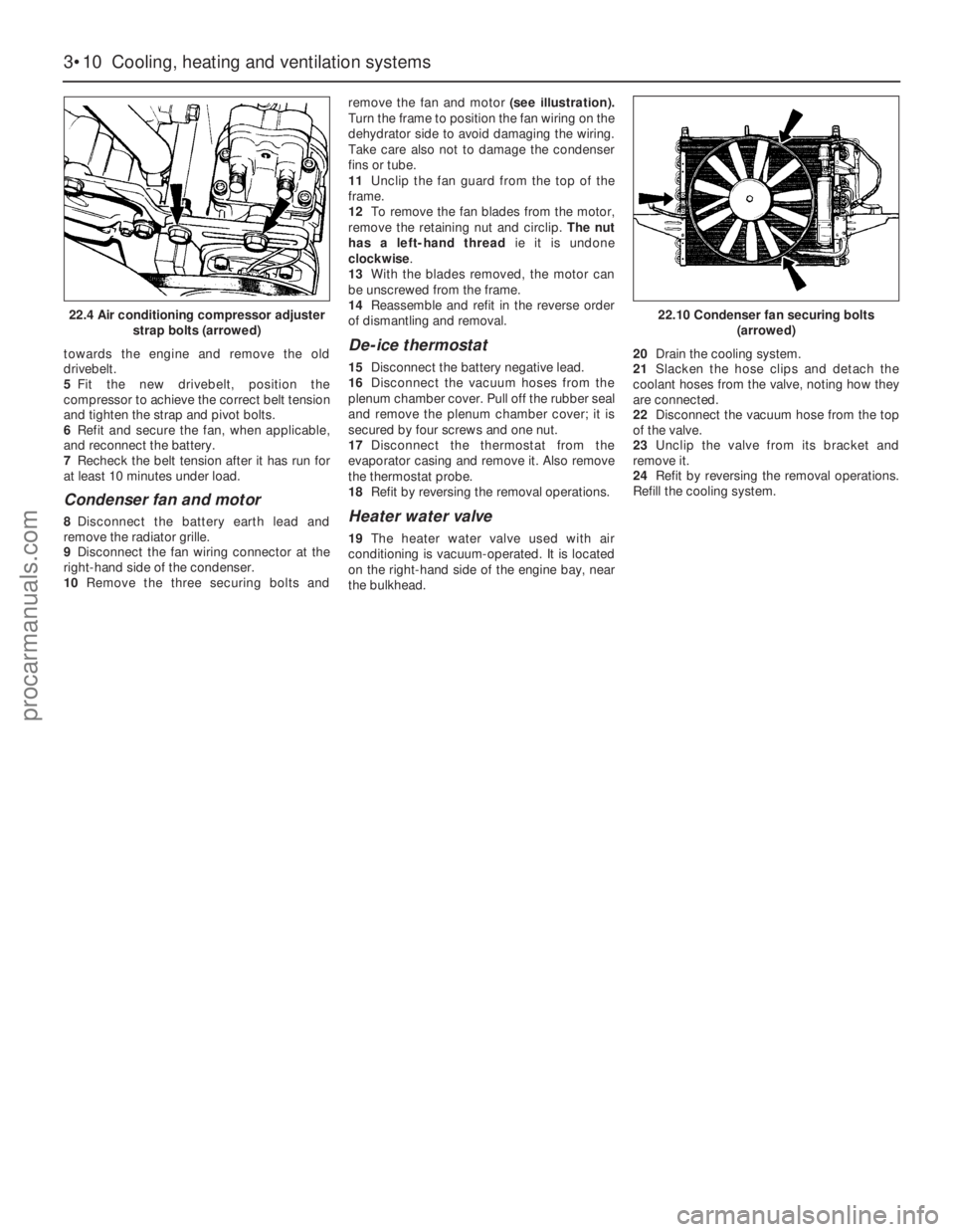
1Only those items which can be renewed
without discharging the system are described
here. Other items must be dealt with by a Ford
dealer or air conditioning specialist (see
illustration).
Compressor drivebelt
2Disconnect the battery earth lead.
3On OHC engines, remove the radiator
cooling fan.
4Slacken the compressor strap and pivot
bolts (see illustration),move the compressor
22Air conditioning system -
component renewal
21Heater coolant valve -
removal and refitting
20Heater matrix - dismantling
and reassembly
Cooling, heating and ventilation systems 3•9
3
19.19 Release the facia wiring loom from
the bulkhead to gain access to the
demister nozzle retaining nut and screw
(arrowed)19.22 Detach the rear footwell nozzles from
the heater assembly
If the heater matrix is blocked
it can sometimes be cleared
by reverse-flushing using a
garden hose and a proprietary
radiator cleaning product if necessary.
22.1 Air conditioning system
component locations
1 De-ice thermostat
2 Evaporator
3 Expansion valve
4 Compressor
5 Compressor clutch
6 Pressure switch
7 Sight glass
8 Dehydrator
9 Cooling fan
10 Condenser
procarmanuals.com
Page 93 of 255
towards the engine and remove the old
drivebelt.
5Fit the new drivebelt, position the
compressor to achieve the correct belt tension
and tighten the strap and pivot bolts.
6Refit and secure the fan, when applicable,
and reconnect the battery.
7Recheck the belt tension after it has run for
at least 10 minutes under load.
Condenser fan and motor
8Disconnect the battery earth lead and
remove the radiator grille.
9Disconnect the fan wiring connector at the
right-hand side of the condenser.
10Remove the three securing bolts andremove the fan and motor(see illustration).
Turn the frame to position the fan wiring on the
dehydrator side to avoid damaging the wiring.
Take care also not to damage the condenser
fins or tube.
11Unclip the fan guard from the top of the
frame.
12To remove the fan blades from the motor,
remove the retaining nut and circlip. The nut
has a left-hand threadie it is undone
clockwise.
13With the blades removed, the motor can
be unscrewed from the frame.
14Reassemble and refit in the reverse order
of dismantling and removal.
De-ice thermostat
15Disconnect the battery negative lead.
16Disconnect the vacuum hoses from the
plenum chamber cover. Pull off the rubber seal
and remove the plenum chamber cover; it is
secured by four screws and one nut.
17Disconnect the thermostat from the
evaporator casing and remove it. Also remove
the thermostat probe.
18Refit by reversing the removal operations.
Heater water valve
19The heater water valve used with air
conditioning is vacuum-operated. It is located
on the right-hand side of the engine bay, near
the bulkhead. 20Drain the cooling system.
21Slacken the hose clips and detach the
coolant hoses from the valve, noting how they
are connected.
22Disconnect the vacuum hose from the top
of the valve.
23Unclip the valve from its bracket and
remove it.
24Refit by reversing the removal operations.
Refill the cooling system.
3•10Cooling, heating and ventilation systems
22.4 Air conditioning compressor adjuster
strap bolts (arrowed)22.10 Condenser fan securing bolts
(arrowed)
procarmanuals.com
Page 101 of 255
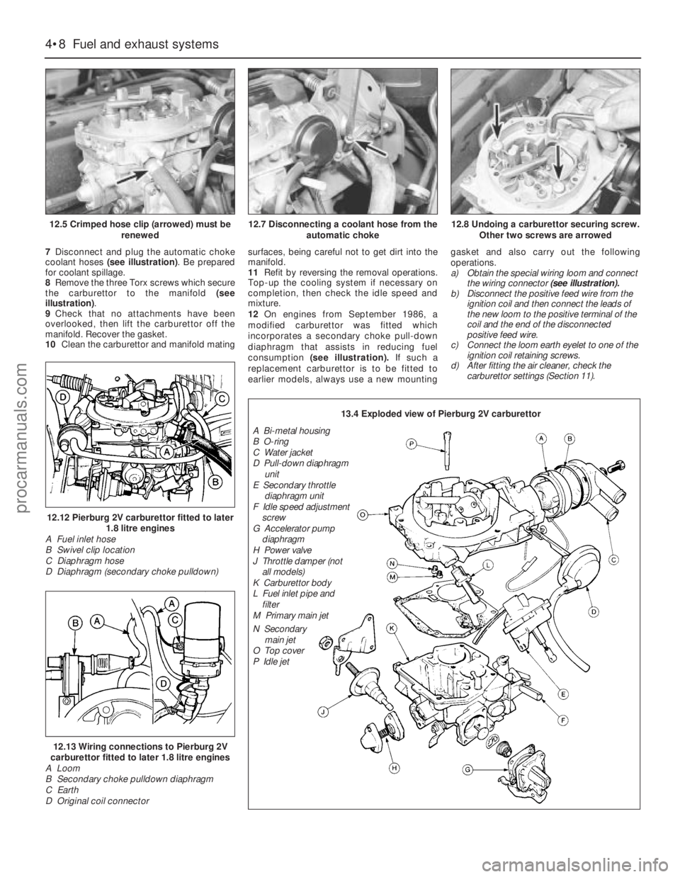
7Disconnect and plug the automatic choke
coolant hoses (see illustration). Be prepared
for coolant spillage.
8Remove the three Torx screws which secure
the carburettor to the manifold (see
illustration).
9Check that no attachments have been
overlooked, then lift the carburettor off the
manifold. Recover the gasket.
10Clean the carburettor and manifold matingsurfaces, being careful not to get dirt into the
manifold.
11Refit by reversing the removal operations.
Top-up the cooling system if necessary on
completion, then check the idle speed and
mixture.
12On engines from September 1986, a
modified carburettor was fitted which
incorporates a secondary choke pull-down
diaphragm that assists in reducing fuel
consumption (see illustration).If such a
replacement carburettor is to be fitted to
earlier models, always use a new mountinggasket and also carry out the following
operations.
a)Obtain the special wiring loom and connect
the wiring connector(see illustration).
b)Disconnect the positive feed wire from the
ignition coil and then connect the leads of
the new loom to the positive terminal of the
coil and the end of the disconnected
positive feed wire.
c)Connect the loom earth eyelet to one of the
ignition coil retaining screws.
d)After fitting the air cleaner, check the
carburettor settings (Section 11).
4•8Fuel and exhaust systems
12.5 Crimped hose clip (arrowed) must be
renewed
12.12 Pierburg 2V carburettor fitted to later
1.8 litre engines
A Fuel inlet hose
B Swivel clip location
C Diaphragm hose
D Diaphragm (secondary choke pulldown)
12.13 Wiring connections to Pierburg 2V
carburettor fitted to later 1.8 litre engines
A Loom
B Secondary choke pulldown diaphragm
C Earth
D Original coil connector
12.7 Disconnecting a coolant hose from the
automatic choke12.8 Undoing a carburettor securing screw.
Other two screws are arrowed
13.4 Exploded view of Pierburg 2V carburettor
A Bi-metal housing
B O-ring
C Water jacket
D Pull-down diaphragm
unit
E Secondary throttle
diaphragm unit
F Idle speed adjustment
screw
G Accelerator pump
diaphragm
H Power valve
J Throttle damper (not
all models)
K Carburettor body
L Fuel inlet pipe and
filter
M Primary main jet
N Secondary
main jet
O Top cover
P Idle jet
procarmanuals.com
Page 109 of 255
9Unscrew the securing nut, and release the
air inlet tube from the bracket on the engine
compartment front panel.
10Disconnect the wiring plug from the idle
speed control valve.
11Release the air cleaner lid securing clips,
then remove the air inlet tube, plenum
chamber, and air cleaner lid as an assembly,
disconnecting the breather hose from the air
inlet tube.
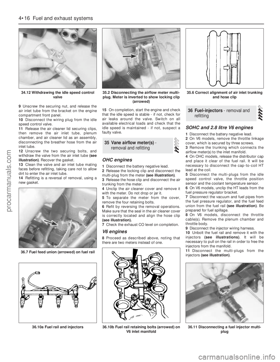
12Unscrew the two securing bolts, and
withdraw the valve from the air inlet tube (see
illustration). Recover the gasket.
13Clean the valve and air inlet tube mating
faces before refitting, taking care not to allow
dirt to enter the air inlet tube.
14Refitting is a reversal of removal, using a
new gasket.15On completion, start the engine and check
that the idle speed is stable - if not, check for
air leaks around the valve. Switch on all
available electrical loads and check that the
idle speed is maintained - if not, suspect a
faulty valve.
OHC engines
1Disconnect the battery negative lead.
2Release the locking clip and disconnect the
multi-plug from the meter (see illustration).
3Release the hose clip and disconnect the air
trunking from the meter.
4Unclip the air cleaner cover and remove it
with the meter. Do not drop or jar it.
5To separate the meter from the cover,
remove the four retaining bolts.
6Refit by reversing the removal operations.
Make sure that the seal in the air cleaner cover
is correctly located and align the hose clip
(seeillustration).
7Check the exhaust CO level on completion.
V6 engines
8Proceed as described above, noting that
there are two meters instead of one.
SOHC and 2.8 litre V6 engines
1Disconnect the battery negative lead.
2On V6 models, remove the throttle linkage
cover, which is secured by three screws.
3Remove the trunking which connects the
airflow meter(s) to the inlet manifold.
4On OHCmodels, release the distributor cap
and place it clear of the fuel rail. It will be
necessary to disconnect the cap-to-coil HT
lead at the coil.
5Disconnect the multi-plugs from the idle
speed control valve, the throttle position
sensor and the coolant temperature sensor.
6On V6 models, unclip the HT leads from the
fuel pressure regulator bracket.
7Disconnect the vacuum and fuel pipes from
the fuel pressure regulator, and the fuel feed
union from the fuel rail (see illustration). Be
prepared for fuel spillage.
8On V6 models, disconnect the throttle
cable(s). Remove the plenum chamber and
throttle body.
9Disconnect the injector wiring harness.
10Unbolt the fuel rail and remove it with the
injectors (see illustrations). It will be
necessary to pull on the rail in order to free the
injectors from the manifold.
11Disconnect the multi-plugs from the
injectors (see illustration).
36Fuel-injectors - removal and
refitting
35Vane airflow meter(s) -
removal and refitting
4•16Fuel and exhaust systems
34.12 Withdrawing the idle speed control
valve
36.7 Fuel feed union (arrowed) on fuel rail
36.10a Fuel rail and injectors36.10b Fuel rail retaining bolts (arrowed) on
V6 inlet manifold36.11 Disconnecting a fuel injector multi-
plug
35.2 Disconnecting the airflow meter multi-
plug. Meter is inverted to show locking clip
(arrowed)35.6 Correct alignment of air inlet trunking
and hose clip
procarmanuals.com